BlackJack SolderWerks BK3001LF User manual

8
TABLE OF CONTENTS
Specifications —————————————————— 2
Safety Precautions ———————————————— 2
Initial Setup ——————————————————— 3
Control Panel Guide ——————————————— 3
Operating Guidelines —————————————— 4
Care and Maintenance —————————————- 4
Basic Troubleshooting Guide ————————–—- 6
BlackJack SolderWerks
BK3001LF
Soldering Station
(Compatible w/Lead-Free Solder)
INSTRUCTION MANUAL
Thank you for purchasing the BlackJack BK3001LF Soldering Station.
Please read this manual before operating the equipment.
Keep manual in accessible place for future reference.

2
Soldering Iron
Power consumption 70W peak
Temperature range: 200°C - 480°C
Heating Element Ceramic Heater
Voltage 24V
SPECIFICATIONS
SAFETY PRECAUTIONS
CAUTION: Improper usage can cause serious injury to personnel
and/or damage to equipment. For personnel safety, please follow
these precautions:
●Check each component after opening the package to make sure everything is in
good condition. Do not use item if visible damage is seen, report the issue to
your vendor.
●Power off unit and unplug the device when moving the device from one location
to another.
●Do not subject the main unit to physical shock
- Never drop or sharply jolt the unit.
- Contains delicate parts that may break if the unit is dropped.
●Always connect power to a grounded receptacle.
●Tip temperature may reach as high as 480°C when switched ON.
- Do not use the device near flammable materials.
- Do not touch heated parts which may include tips, nozzles, barrels.
●Disconnect from power source if the unit will not be used for a long periods.
Switch off power during short breaks.
●Use only genuine replacement parts.
●Soldering process produces smoke — use on well ventilated place.
●Do not try to alter or repair unit, bring to qualified service center for repairs.
Specifications are subject to change without prior notice
7
BASIC TROUBLESHOOTING GUIDE
PROBLEM 5: SOLDERING IRON DOES NOT PRODUCE ENOUGH HEAT
Description: Soldering iron cannot melt solder fast enough, or actual tem-
perature does not reach the desired set temperature.
SOLUTION:
The system may need to be recalibrated please
Soldering iron tip may already be too dirty or oxidized .
PROBLEM 6: UNIT PRODUCES ERROR BEEPING SOUNDS
Description: The solder iron produced three being sounds.
SOLUTION:
Soldering iron is not properly connected to its receptacle.
Soldering iron tip is not inserted fully or correctly.
6
BASIC TROUBLESHOOTING GUIDE
PROBLEM 1: THE UNIT HAS NO POWER /MAIN POWER LED DOES
NOT LIGHT UP
1. Check if the unit is switched ON.
2. Check the fuse. Replace with the same type of fuse if blown.
3. Check the power cord and make sure there are no disconnections.
4. Verify that the unit is properly connected to the power source.
PROBLEM 2: SOLDERING IRON DOES NOT RISE IN TEMPERATURE
Description: Main power LED lights up and so does the heater LED but sol-
dering iron temperature is relative low and is not heating up.
SOLUTION:
Soldering iron cord may be damaged and needs to be replaced or
repaired.
Heating element may be damaged and needs to be replaced
PROBLEM 3: SOLDERING IRON TEMPERATURE IS INTERMITTENT
Description: Main power LED lights up and so does the heater LED but sol-
dering iron temperature rises and falls uncontrollably.
SOLUTION:
Soldering iron plug may be loose from the receptacle unplug the
soldering iron and reattach.
Soldering iron cord may be damaged or loose and needs to be
replaced or repaired. See trouble shooting soldering iron cords
section of this manual.
PROBLEM 4: SOLDER WOULD NOT STICK TO THE SOLDERING TIP
Description: Soldering iron is able to quickly melt solder but cannot cause
the solder to attach to the tip.
SOLUTION:
Soldering iron tip may already be too dirty or oxidized . Please see
our solder tip maintenance guide on how to clean soldering tips.
Temperature could be set too high causing solder to quickly burn
away, Please adjust to a more suitable lower temperature range.
3
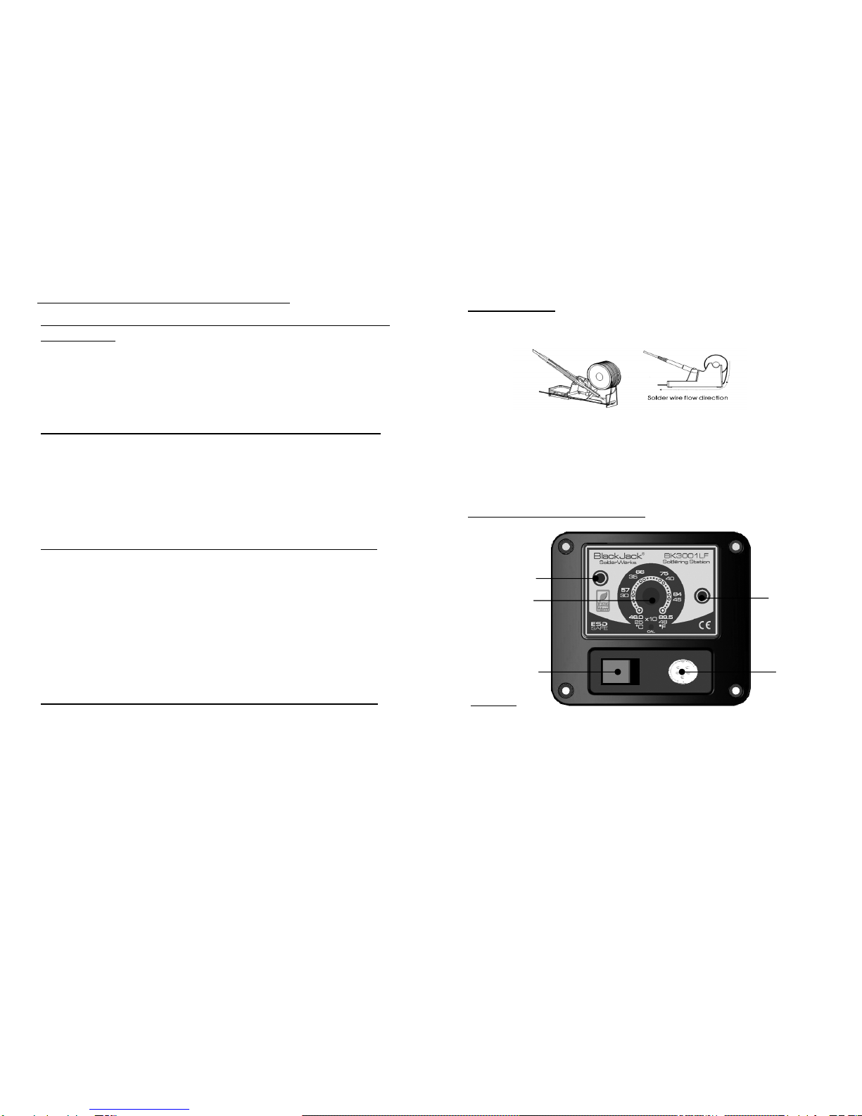
Initial Setup
Soldering Iron
1. Install the solder wire to the soldering iron holder as seen.
2. Connect the soldering iron cord assembly to the 6-pin output terminal
found at the lower middle portion of the main unit.
3. Place the soldering iron to the soldering iron stand as shown above.
4. Dampen the sponge and place into sponge tray.
LEGEND:
1 — Power lamp
2 — Soldering Iron Temp Control knob
3 — Heater Lamp
4 — Main Power Switch
5 — Soldering Iron Receptacle
CONTROL PANEL GUIDE
3
5
1
2
4

4
OPERATING GUIDELINES
Please refer to the CONTROL PANEL GUIDE page for buttons and
display panel directory.
1. INITIAL PROCEDURES
1. Plug the device to the main power source.
2. Make sure power switches are deactivated
3. Attach Solder iron to its receptacle.
2. SOLDERING
1. Switch ON unit.
2. Adjust temperature with temperature control knob (“3” from the
control panel).
3. The system will rapidly increase temperature to the tip. The heater
lamp will continue to be lit.
4. When temperature has reached set level, heater lamp will start to
blink. A beep will be heard.
5. Start soldering when temperature has been reached desired level.
CARE and MAINTENANCE
●Use lowest *possible* tip temperature when soldering.
●The soldering iron tip should be cleaned after use by wiping it on
the damp sponge found in the soldering iron stand. This is to get
rid of burnt solder or fluxes that causes oxidation on the tip.
●Maintain a thin layer or solder over the tip when iron is not being
used. This maintains the tinning on the tip, and the tip will last
much longer.
5
CARE and MAINTENANCE
●Changing TIP
1. Always turn the power OFF when removing or inserting a tip.
2. When the tip is hot, hold it with the heat resistant pad and pull it
out.
3. Insert the new tip fully into the handle. If the tip is not fully in-
serted, unit will produce three beeping sounds.
● Checking, Cleaning and Tinning the Tip
1. Set temperature to 250°C (482°F)
2. After real temperature reaches the set temperature, use a
damp sponge to clean the tip and check for damages.
3. If the tip has oxidation, apply solder and wipe using the damp
sponge, repeat these steps until oxidation is removed.
4. After cleaning, coat tip with a thin layer of solder and set it
aside ready for the next usage.
5. If the tip shows disfiguration or has rust on it. Change the tip.
●Calibrating the Tip Temperature
1. Plug in station and turn it on.
2. Set temperature to 400°C (750°F)
3. Wait for Heater LED to light up.
4. Use an external sensor and place it on the solder tip.
5. Take off the rubber stop in the CAL point. Use a screwdriver,
one that fits the CAL hole, to adjust the CAL point.
6. Adjust until the external sensor reads 400°C (750°F).
●Checking the fuse
1. The Fuse can be found at the back of the unit, it is incorpo-
rated into the AC power receptacle. If fuse is blown replace
with same type fuse only.
Table of contents
Popular Soldering Gun manuals by other brands

Hakko Electronics
Hakko Electronics FP-948 instruction manual

ACTION ELECTRONICS
ACTION ELECTRONICS WES51 quick start guide

Fahrenheit
Fahrenheit 28025 manual

Taiyo Electric
Taiyo Electric Goot RX-852AS Operation manual

Craftsman
Craftsman 113.540440 owner's manual

Somogyi Elektronic
Somogyi Elektronic Home SMA 5051T instruction manual


