jbc SF User manual

Español 12
Automatic Solder Feeder
Ref. SF
English 2
Page
www.jbctools.com

Packing List
The following items should be included:
Manual ...............................1 unit
Ref. 0019329
Allen key Ø 1,5 ................1 unit
Ref. 0741610
SF Control Unit ............. 1 unit
Ref. SF-110VA (10 0-120V )
SF-210VA (230V)
Allen key Ø 2,5 ................1 unit
R ef. 0 0125 74
Reel support ................ 1 unit
Ref. 0018032
0018033
0003412 (x2)
Power cable .................... 1 unit
Ref. 0009417 (100V/120V)
0009401 (230V)
Spanner ............................ 1 unit
Ref. 0017631
Guide Set ........................1 unit
Ref. GSF10V - wire Ø 1 mm
Automatic Solder Feeder
Ref. SF-A
lock rings
Solder Feed
Handle .............................. 1 unit
Ref. SF280-A
2
www.jbctools.com

Power Socket
Fuse
RJ12 connection
for Robot System
USB-B connector
Tin wire inlet
Features
Solder Feed Handle
Ref. SF280-A
Control Unit
Main Switch
Control
Screen
www.jbctools.com
3

Tool assembly
Connect the tool to the control
unit.
1. Push the guide to the end
and tighten the screw.
2. Connect the jack.
Load the solder wire
1. Use the lock rings to prevent the reel from sliding on the bar.
2. Feed the wire into the guide (2) until it reaches the drag wheels.
1
1
2
Guide tube
1
2
3. Press the button on the tool
or the wire-load button on the
station.
4. Make sure the wire passes
through the tube.
insert to the end
4

Changing the drag wheels and the blade
1. Use the allen key and the spanner to loosen
the screws.
2. Replace the drag wheels and the blade with
the new ones.
Fixing the guide tube
1. You can easily adjust the length of the tube by opening the guide clamp.
Drag
wheel
Drag
wheel
Blade
www.jbctools.com
5

Back
Setting Program 35
Continuous Mode Discontinuous Mode Program 35
Speed Length Length
STEP1 STEP2
Speed Speed
SUPPLIED:2.0mm/5s 40% 40%
mm/s mm mmmm/s mm/s
40 1.5 1.520 20
STEP3
Length Speed
mm mm/s
5.0 20.0
STEP 1
STEP 2
STEP 3
Back
Edit Program
mm
mm/s
STEP 1 STEP 2 STEP 3
35
5.0 3.0 1.5
20.0 24.5 20.0
FACTORY 1 1Program35
FACTORY1
2Program22
LAB2
3Program35
FACTORY1
Program Concatenation
Back
Work Screen
Control Process
Choose between continuous, discontinuous and program mode:
Program mode
With the SF you can define up to 35 dynamic programs. In each one you can configure up to 3
steps with different lenght wire and dispensing speed.
Execute them sequentially and cyclically with the ‘Edit Concatenation List’ option.
6

Main Menu
5 Tin Reload Process
6 Counters
7 Software Version
1 Reset settings
2
Station settings
3
Tool settings
4 Programs Settings
Back
Exit
1 Length units*
mm
2
Beep Off
3
Change PIN
1 Mode
Discontinuous
2
Backward Off
Tool Settings
Station Settings
Back
Back
1 Edit Program
2
Delete Program
3
Edit Concatenation List
Program Settings
Back
1 Manual Reload
2
Automatic Reload
Reload Menu
1 Plugged hours
7605
2
Working hours 350
3 Supplied mm 560
4 Work Cycles 75830
Counters
Back
5 Reset partial counters
Press Enter to toggle*
Screen Menu
Original PIN: 0105
Control Process
*switch total and partial
counters
*switch mm and inches
www.jbctools.com
7

Accesories
Solder Feed Handle Stand
Ref. SF-SD
It prevents the SF280-A Solder Feed Handle
from rolling away while working.
Guide Set
Ref. GSF08V - wire Ø 0,8 mm
Ref. GSF15V - wire Ø 1,5 mm
You can change the guide set depending on
the solder wire used.
8

Before carrying out maintenance, always allow the equipment to cool down.
Clean
periodically
- Clean the station screen with a glass cleaner
or a damp cloth.
- Use a damp cloth to clean the casing and the
tool. Alcohol can only be used to clean the
metal parts.
- Periodically check that the metal parts of the
tool and stand are clean so that the station
can detect the tool’s status.
- Periodically check all cables and tubes.
Maintenance
1. Pull off the fuse holder and remove the
fuse. If necessary use a tool to lever it off.
2. Insert the new fuse into the fuse holder
and return it to the station.
- Replace a blown fuse as follows:
- Replace any defective or damaged pieces. Use original JBC spare parts only.
- Repairs should only be performed by a JBC authorized technical service.
www.jbctools.com
9

- Do not use the units for any purpose other than soldering or rework. Incorrect use may cause fire.
- The power cord must be plugged into approved bases. Make sure that it is properly grounded
before use. When unplugging it, hold the plug, not the wire.
- Do not work on electrically live parts.
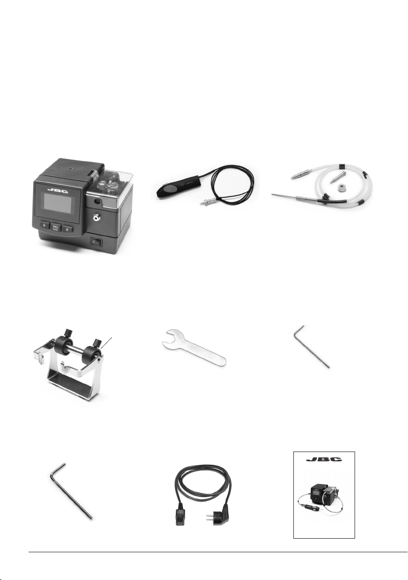
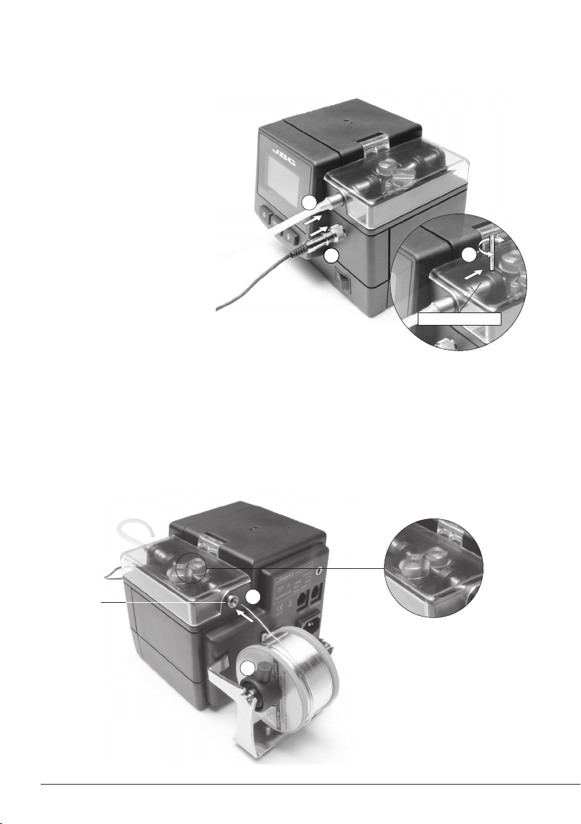
- The tool should be placed in the stand when not in use.
Handle with care, including when adjusting the stand position.
- Do not leave the appliance unattended when it is on.
- Do not cover the ventilation grills. Heat can cause inflamable products to ignite.
- Avoid the contact of flux with skin or eyes to prevent irritation.
- Be careful with the fumes produced when soldering.
- Keep your workplace clean and tidy. Wear appropriate protection glasses and gloves when
working to avoid personal harm.
- Utmost care must be taken with liquid tin waste which can cause burns.
- This appliance can be used by children over the age of eight as well as persons with reduced
physical, sensory or mental capabilities or lacking experience provided that they have been given
adequate supervision or instruction concerning use of the appliance and understand the hazards
involved. Children must not play with the appliance.
- Maintenance must not be carried out by children unless supervised.
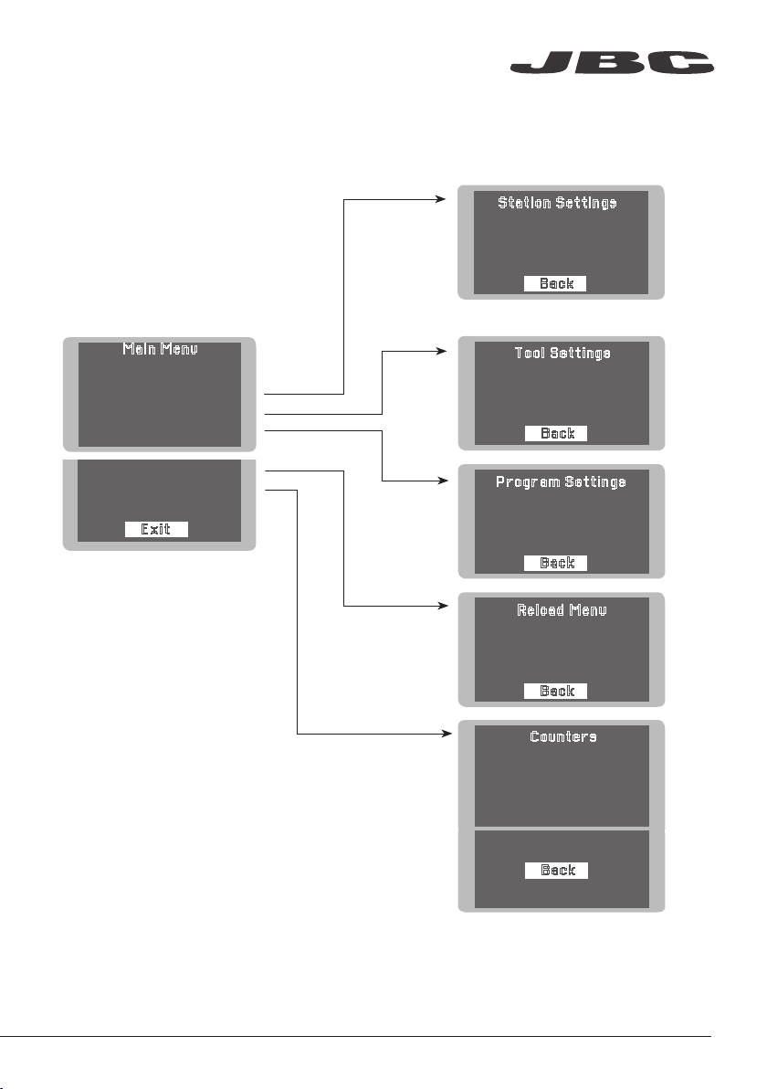
Safety
It is imperative to follow safety guidelines to prevent electric
shock, injury, fire or explosion.
10

Specifications
SF-110VA 100-120V 50/60Hz. Input fuse: 0.2A.
SF-210VA 230V 50/60Hz. Input fuse: 0.1A.
- Weight: 1.9 Kg [4.2 lb]
- Dimensions: 150 x 120 x 115 mm [5.9 x 4.8 x 4.6 in]
- Spool capacity up to 1 kg [2.2 Ib]
- Solder diameter Ø 1 mm [0.04 in]
- Max. Wire lenght 250 mm [9.84 in]
- Max. Forward speed 120 mm/s [4.72 in/s]
- Max. Reverse speed 120 mm/s [4.72 in/s]
- Ambient operating temp: 10 - 40 ºC [50 - 104 ºF]
- USB connector station-PC
- Robot connector
Complies with CE standards
ESD protected housing “skin effect”
www.jbctools.com
11

Composición
Los siguientes artículos deben estar incluidos:
Manual .........................1 unidad
Ref. 0019329
Allen key Ø 1,5
Llave Allen Ø 1,5 ....... 1 unidad
Ref. 0741610
SF Control Unit
Unidad de control SF ......... 1 u
Re f. SF -110VA (10 0 -120V )
SF-210VA (230V)
Allen key Ø 2,5
Llave Allen Ø 2,5 ....... 1 unidad
R ef. 0 0125 74
Reel support
Soporte bobina ......... 1 unidad
Ref. 0018032
0018033
0003412 (x2)
Power cable
Cable conector ......... 1 unidad
Ref. 0009417 (100V/120V)
0009401 (230V)
Spanner
Llave Inglesa .............. 1 unidad
Ref. 0017631
Guide Set
Conjunto guía ............ 1 unidad
Ref. GSF10V - hilo de Ø 1 mm
anillos de
bloqueo
Solder Feed Handle
Mango con aportacón
de estaño ................. 1 unidad
Ref. SF280-A
Automatic Solder Feeder
Ref. SF-A
12
www.jbctools.com

Entrada de red
Fusible
Conector
para robot RJ12
Puerto USB-B
Entrada hilo
de estaño
Características
Mango con
aportación de estaño
Ref. SF280-A
Unidad de control
Interruptor
principal
Pantalla
de control
www.jbctools.com
13

Montaje de la herramienta
Conecte la herramienta con la
unidad de control.
1. Empuje la guía hasta el final
y apriete el tornillo.
2. Conecte el jack.
Carga del hilo de estaño
1. Utilice los anillos de bloqueo para evitar que la bobina se deslice sobre la barra.
2. Introduzca el hilo dentro de la guía (2) hasta que alcance las ruedas de arrastre.
1
1
2
Tubo guía
1
2
3. Presione el botón de la
herramienta o el botón de
carga de hilo de la estación.
4. Asegúrese de que el hilo
pase a través del tubo.
insertar hasta el final
14

Cambio de las ruedas de arrastre
y de la cuchilla
1. Utilice la llave allen y la llave inglesa para
aflojar los tornillos.
2. Reemplace las ruedas de arrastre y la
cuchilla por las nuevas.
Ajuste del tubo guía
1. Ajuste fácilmente la longitud del tubo guía desbloqueando el cierre mediante la palanca.
Rueda
de arrastre
Rueda
de arrastre
Cuchilla
www.jbctools.com
15

Back
Setting Program 35
Continuous Mode Discontinuous Mode Program 35
Speed Length Length
STEP1 STEP2
Speed Speed
SUPPLIED:2.0mm/5s 40% 40%
mm/s mm mmmm/s mm/s
40 1.5 1.520 20
STEP3
Length Speed
mm mm/s
5.0 20.0
STEP 1
STEP 2
STEP 3
Back
Edit Program
mm
mm/s
STEP 1 STEP 2 STEP 3
35
5.0 3.0 1.5
20.0 24.5 20.0
FACTORY 1 1Program35
FACTORY1
2Program22
LAB2
3Program35
FACTORY1
Program Concatenation
Back
Pantalla de trabajo
Control del proceso
Seleccione entre el modo de trabajo continuo, discontinuo y programa:
Modo programa
Con el SF puede determinar hasta 35 programas dinámicos. En cada uno se pueden configurar
hasta 3 pasos con diferentes longitudes de hilo y velocidades de dispensado.
Puede ejecutarlos secuencial y cíclicamente con la opción ‘Edit Concatenation List’.
16

Main Menu
5 Tin Reload Process
6 Counters
7 Software Version
1 Reset settings
2
Station settings
3
Tool settings
4 Programs Settings
Back
Exit
1 Length units*
mm
2
Beep Off
3
Change PIN
1 Mode
Discontinuous
2
Backward Off
Tool Settings
Station Settings
Back
Back
1 Edit Program
2
Delete Program
3
Edit Concatenation List
Program Settings
Back
1 Manual Reload
2
Automatic Reload
Reload Menu
1 Plugged hours
7605
2
Working hours 350
3 Supplied mm 560
4 Work Cycles 75830
Counters
Back
5 Reset partial counters
Press Enter to toggle*
Pantalla de menú
PIN original: 0105
Control del proceso
*cambiar contadores totales
y parciales
*cambiar a mm o pulgadas
www.jbctools.com
17

Accesorios
Soporte para mango
con aportacón de estaño
Ref. SF-SD
Evita que el mango con aportación de estaño
SF280-A se caiga mientras trabaja.
Conjunto guía
Ref. GSF08V - hilo de Ø 0,8 mm
Ref. GSF15V - hilo de Ø 1,5 mm
Puede cambiar el conjunto guía en función
del diámetro del hilo a usar.
18

Antes de almacenar o de su mantenimiento, desconecte el equipo y déjelo enfriar.
Limpie
periódicamente
- Limpie la pantalla de la estación con un
limpiador de vidrios o un paño húmedo.
- Use un paño húmedo para limpiar. Sólo
utilice alcohol para las partes metálicas.
- Compruebe periódicamente que las partes
metálicas de la herramienta y del soporte
están limpias, así la estación podrá detectar
el estado de la herramienta.
- Compruebe periódicamente todos los cables
y tubos.
Mantenimiento
1. Retire el fusible tirando de la tapa negra.
Si fuera necesario, utilice una palanca.
2. Coloque el nuevo fusible en su sitio y
vuelva a insertarlo en la estación.
- Cambie el fusible fundido de acuerdo a las siguientes instrucciones:
- Cambie cualquier pieza defectuosa o dañada. Utilice solamente recambios originales de JBC.
- Cualquier reparación sólo podría ser realizada por un servicio técnico oficial JBC.
www.jbctools.com
19

- No utilice las unidades para otros fines que no sea la soldadura o reparación. El uso incorrecto
puede causar fuego.
- El cable de red debe enchufarse en bases homologadas. Asegúrese de que está conectado a
tierra correctamente antes de su uso. Al desenchufarlo, tire del conector, no del cable
- No trabaje con tensión.
- La herramienta debe permanecer en el soporte cuando no está en uso. Manipule con cuidado,
incluso cuando ajuste la posición del soporte.
- No deje el aparato desatendido cuando esté en funcionamiento.
- No cubra las rejillas de ventilación. El calor puede causar que los productos inflamables se
enciendan.
- Evite el contacto del Flux con la piel o los ojos para prevenir la irritación..
- Tenga cuidado con el humo producido al trabajar.
- Mantenga su lugar de trabajo limpio y ordenado. Use gafas y guantes de protección adecuados.
Así evitará cualquier daño.
- Tenga cuidado con los restos de estaño líquido. En contacto con la piel, puede causar quemaduras.
- Este aparato puede ser utilizado por personas a partir de 8 años y también por aquellas personas
con movilidad reducida o capacidades físicas, sensoriales o mentales limitadas o con falta de
experiencia y conocimientos siempre y cuando reciban supervisión o instrucciones relativas al uso
del aparato de una manera segura y entiendan los riesgos que implica. Los niños no deben jugar
con el aparato.
- Los niños no deberán realizar tareas de mantenimiento sin supervisión.
Seguridad
Es necesario seguir estas directrices de seguridad para proteger su salud y
prevenir cualquier choque eléctrico, heridas, fuego o explosiones.
20
Other manuals for SF
2
This manual suits for next models
2
Table of contents
Languages:
Other jbc Soldering Gun manuals