Blackmagicdesigngi Videohub Master Control User manual
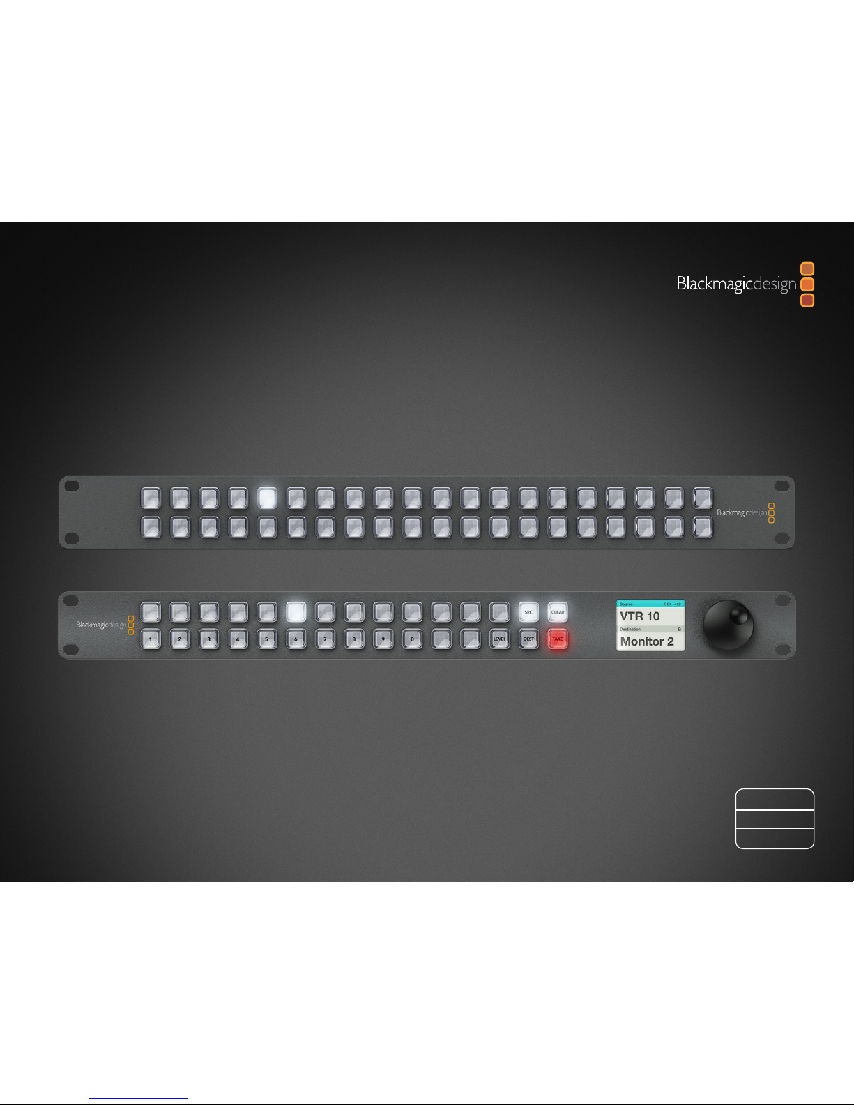
Installation and Operation Manual
Videohub Control
Windows™
November 2012
Mac OS X™
Contents
Videohub Operation Manual
Planning Your Videohub Installation
Videohub Master Control 5
Videohub Smart Control 7
Hardware Installation
Connecting Videohub Control Panels with Ethernet 9
Connecting Videohub Control Panels with USB 12
Labelling Control Panels 13
Software Installation
Installing the Videohub Control Utility Software 14
Updating the Software in Your Videohub Control Panel 15
Configuring the Videohub Control Utility Software 16
Videohub Master Control Settings 18
Videohub Smart Control Settings 20
5
14
9
22
31
Using Hardware Control Panels
Using Videohub Master Control 22
Using Videohub Smart Control 29
Help
Warranty Information
32

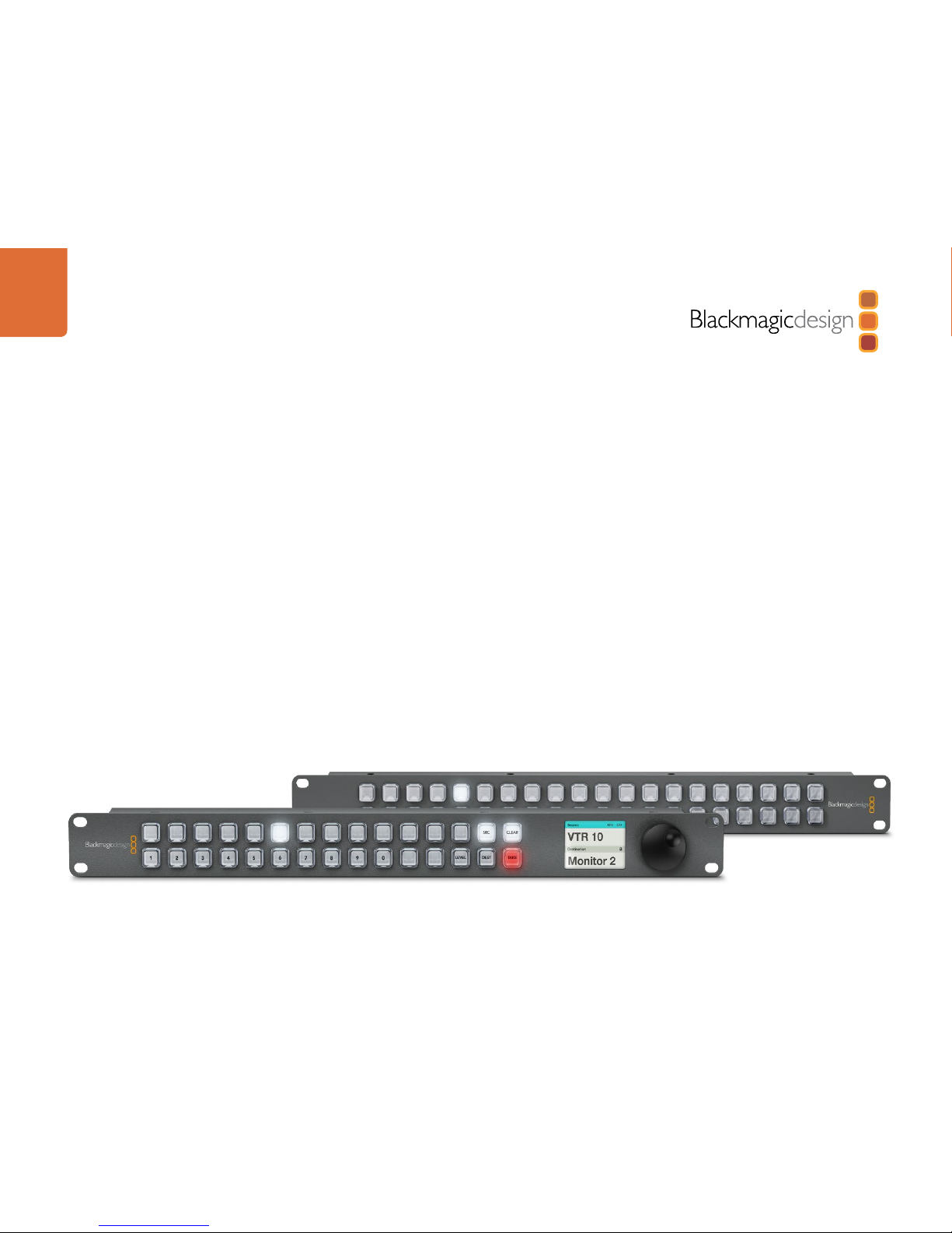
Welcome
3
Welcome to Videohub Control!
Videohub Master Control and Videohub Smart Control are simple to install. We've extracted the relevant
pages from the Videohub manual so you don't need to read too much. All the information in this mini
manual can also be found in the Videohub manual.
We hope you share our dream for the television industry to become a truly creative industry by allowing
anyone to have access to the highest quality video.
Previously high end television and post production required investment in millions of dollars of hardware,
and professional SDI routing switchers have always been way too high in cost for most people to afford.
HD-SDI is even worse and until now, only the largest post production and television facilities could afford
HD-SDI routing. Videohub changes all that and even enables you to pipe 2K film around your studio just
like video. Now Videohub Control makes it even easier to route video using dedicated, broadcast quality,
hardware control panels that are also affordable. We hope you get years of use from it and have lots of fun
connecting everyone in your facility together!
This instruction manual should contain all the information you’ll need on installing your Videohub Control,
although it’s always a good idea to ask a technical assistant for help if you are not sure what IP addresses
are, or if you don’t know much about computer networks. Videohub Control is easy to install, however,
there are a few slightly technical preferences you will need to set after you install it.
We think it should take you approximately 5 minutes to complete installation. Please check our web site at
www.blackmagicdesign.com and click the support page to download the latest updates to this manual and
Videohub software including the Blackmagic Videohub Control Utility. Lastly, please register your Videohub
Control when downloading software updates so we can keep you updated when new software is released.
We are constantly working on new features and improvements, so we would love to hear from you!
Grant Petty
CEO Blackmagic Design

Welcome
4
How to read as little of this manual as possible
Most people only need to read one or two pages out of each section of this manual and there is no need to
read every page. Here is what you'll learn in each section.
Planning
First, go to the "Planning your Videohub Installation" section for your Videohub Master Control or Videohub
Smart Control. This section provides you with all the information you need to know before buying or installing
a Videohub control panel. You can plan how to set it up so there are no nasty surprises.
Hardware Installation
Hardware Installation covers connection of Videohub Control via Ethernet and USB as well as how to make
neat labels and avoid damaging the unit.
Software Installation and Configuration
Now it's time to install and configure the software for your Videohub Control.
Routing Video
Now that the hardware and software is set up, it's time to start routing video!
Planning Your Videohub Installation
5
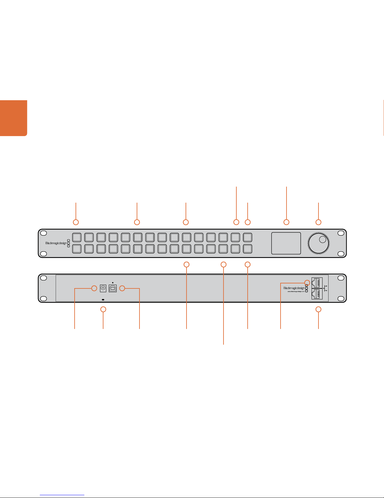
Videohub Master Control
USB 2.0 for adjusting
settings and software
updates
Illuminated buttons with
customizable backlight
Button Caps can
be removed for
custom labelling
Source/Destination
Buttons
Take Button to
confirm routing
changes
Scroll Wheel for
scrolling through sources
and destinations
Clear
Selection
Button
Level Button for
independent RS-422
control from SDI
Configurable buttons provide
fast selection of common
equipment types, e.g. cameras
Power over
Ethernet network
connection to
Videohub router
Ethernet loop
through to other
network devices
Cable tie
point
+12 volt
power supply
connection
USB OUT
IN
POWER
+12V
1 2 3 4 5 6 7 8 9 0 LEVEL DEST
SRC CLEAR
TAKE
USB OUT
IN
POWER
+12V
1 2 3 4 5 6 7 8 9 0 LEVEL DEST
SRC CLEAR
TAKE
LCD for Source and
Destination Labels
Numeric buttons for fast
selection of ports with
numeric labels
Planning Your Videohub Installation
6
Planning your Videohub Master Control Installation
Videohub Master Control is a rack-mountable control panel, with 30 backlit pushbuttons, LCD, scroll wheel
and Ethernet connectivity designed to perform Videohub crosspoint switching without using a computer. In
contrast to Videohub Smart Control, which can control a combined maximum of 40 sources and destinations,
Videohub Master Control can control all sources and destinations for any size of Videohub router, as well as
RS-422 deck control.
The front panel of Videohub Master Control can be removed to allow insertion of labels under the buttons.
All 30 pushbuttons can be variably backlit to ensure the labels can be easily read, even in dark rooms.
Videohub Master Control uses Videohub port labels to aid in fast selection of equipment. 15 buttons can
be configured and labelled to provide fast selection of common equipment types, e.g. cameras, VTRs
and monitors. Before labelling any of the 15 buttons, you will need to standardize the port labels on your
Videohub. Please refer to the "How to Label Buttons in Videohub Master Control" section of this manual for
detailed instructions about standardizing Videohub port labels and also how to label buttons in Videohub
Master Control using the Blackmagic Videohub Control Utility. The Blackmagic Videohub Control Utility
runs on Mac OS X and Windows computers and uses a USB 2.0 connection to Videohub Master Control for
initial configuration. You will need to provide a USB 2.0 type A to B male cable.
This same USB cable can be used for applying internal software updates downloaded from the Blackmagic
Design website. Internal software can provide new features, compatibility with new hardware and support
for new formats. The Blackmagic Videohub Control Utility is used to apply internal software updates, on
Mac OS X and Windows computers, and uses a USB 2.0 connection to Videohub Master Control.
Videohub Master Control connects to any Videohub via 10/100Base-T Ethernet networking and also includes
a loop through Ethernet port for connecting to additional control panels, Videohub routers or other network
devices. You will need to provide a standard RJ45 Ethernet network cable to connect Videohub Master
Control to your Ethernet network switch.
Videohub Master Control features power over Ethernet meaning no external power supply is required if
used with a power over Ethernet switch. If your Ethernet switch does not provide power over Ethernet,
use the included universal power supply with international power socket adapters for all countries.
To stop power from being accidentally disconnected, a cable tie point is included just below the power
socket to lock down the power connection. You will need to provide a mains power socket for the universal
power supply.
Videohub Master Control is 1 rack unit high and less than an inch thick. You will need to leave enough space
in your equipment rack to install the Videohub Master Control hardware. You can rack-mount Videohub
Master Control at the front or at the rear of the rack to leave space for other equipment.

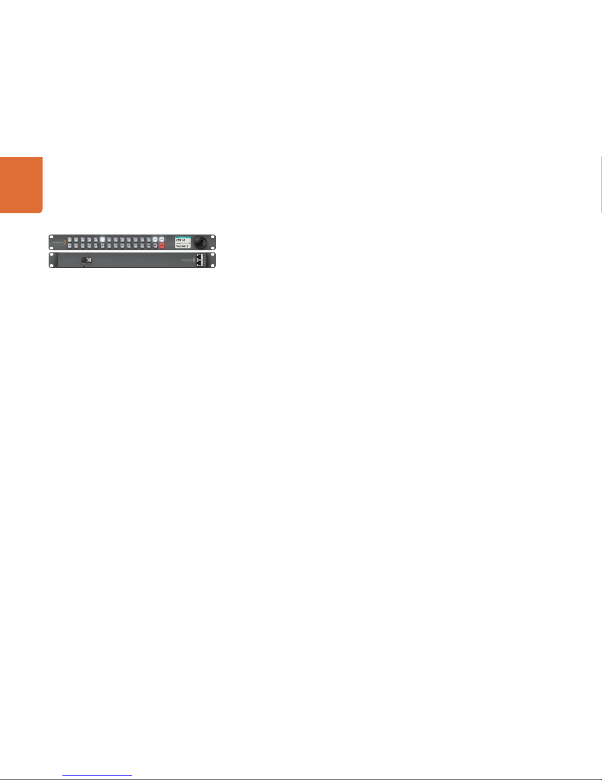
Planning Your Videohub Installation
7
Videohub Smart Control
Single or multiple
destinations
supported
Button caps can
be removed for
custom labelling
Take button
can be enabled
+12 volt
power supply
connection
Ethernet loop
through to other
network devices
Power over
Ethernet network
connection to
Videohub router
Illuminated
buttons for router
source selection
USB 2.0 for adjusting
settings and software
updates
Cable tie point
Buttons can be
customized as
macros

Planning Your Videohub Installation
8
Planning your Videohub Smart Control Installation
Videohub Smart Control is a rack-mountable control panel, with 40 backlit pushbuttons and Ethernet
connectivity, which works with all models of Videohub. It can be configured to work with one or many SDI
destination devices, using the included software utility for Mac OS X and Windows. Once configured for
your SDI equipment and Videohub router, Videohub Smart Control no longer requires a computer and can
immediately change SDI routes as desired.
The front panel of Videohub Smart Control can be removed to allow insertion of labels under the buttons.
All 40 pushbuttons can be variably backlit to ensure the labels can be easily read, even in dark rooms.
When configured for a single SDI destination, such as a monitor or deck, the pushbuttons can instantly
switch between 40 different SDI sources on the same Videohub router. When configured for multiple SDI
destinations, destination buttons become gold colored, source buttons become white, and the lower
right button can be configured as a take button and illuminates red. Macro buttons illuminate green
when enabled and each one can be configured to perform up to 16 simultaneous crosspoint switches.
The Blackmagic Videohub Control Utility runs on Mac OS X and Windows computers and uses a USB 2.0
connection to Videohub Smart Control for initial configuration. You will need to provide a USB 2.0 type A
to mini B male cable.
This same USB cable can be used for applying internal software updates downloaded from the Blackmagic
Design website. Internal software can provide new features, compatibility with new hardware and support
for new formats. The Blackmagic Videohub Control Utility is used to apply internal software updates, on
Mac OS X and Windows computers, and uses a USB 2.0 connection to Videohub Smart Control.
Videohub Smart Control connects to any Videohub via 10/100Base-T Ethernet networking and also includes
a loop through Ethernet port for connecting to additional control panels, Videohub routers or other network
devices. You will need to provide a standard RJ45 Ethernet network cable to connect Videohub Smart
Control to your Ethernet network switch.
Videohub Smart Control features power over Ethernet meaning no external power supply is required if
used with a power over Ethernet switch. If your Ethernet switch does not provide power over Ethernet,
use the included universal power supply with international power socket adapters for all countries.
To stop power from being accidentally disconnected, a cable tie point is included just below the power
socket to lock down the power connection. You will need to provide a mains power socket.
Videohub Smart Control is 1 rack unit high and less than an inch thick. You will need to leave enough space
in your equipment rack to install the Videohub Smart Control hardware. You can rack-mount Videohub
Smart Control at the front or at the rear of the rack to leave space for other equipment. When configured
for a single SDI destination, install Videohub Smart Control immediately under an SDI deck or monitor you
wish to control. If you don’t have a rack, then you can leave it in a safe place on the floor!

Hardware Installation
9
Connecting Videohub Control Panels with Ethernet
Videohub Master Control and Videohub Smart Control connect to any Videohub via standard Ethernet
networking and can be powered over Ethernet or with an external power supply. Videohub control panels
have two 10/100Base-T Ethernet ports. The In port usually connects directly to the Ethernet network
switch and then to any Videohub router on your local area IP based network. Alternatively the In port can
connect directly to any Ethernet-equipped Videohub using a standard Ethernet cable and without the
need for a network switch. The Out port provides a loop through Ethernet connection to additional control
panels, Videohub router or other network devices. The loop through Ethernet connection is useful if you
want to add a Videohub control panel to your network without having to run an additional cable back to
the network switch.
You will need to carry out the following steps to connect a Videohub control panel to the local area IP based
network.
Step 1. Videohub control panels feature power over Ethernet meaning no external power supply is
required if used with a power over Ethernet switch. You can skip this step if your network switch
provides power over Ethernet. Otherwise connect the included power supply to your Videohub
control panel. No problem will be caused by connecting the power supply and power over
Ethernet at the same time.
Step 2. Use the network In port on your Videohub control panel to connect to your network switch, or
directly to an Ethernet-equipped Videohub, with a standard RJ45 Ethernet cable.
Step 3. You might also wish to connect another network device to the network Out port on your Videohub
control panel, such as a Videohub router, another Videohub control panel or other network
devices such as a computer or VoIP phone. The Out port does not provide power over Ethernet
and any network device connected to this port will require its own power supply.
Hardware Installation
10
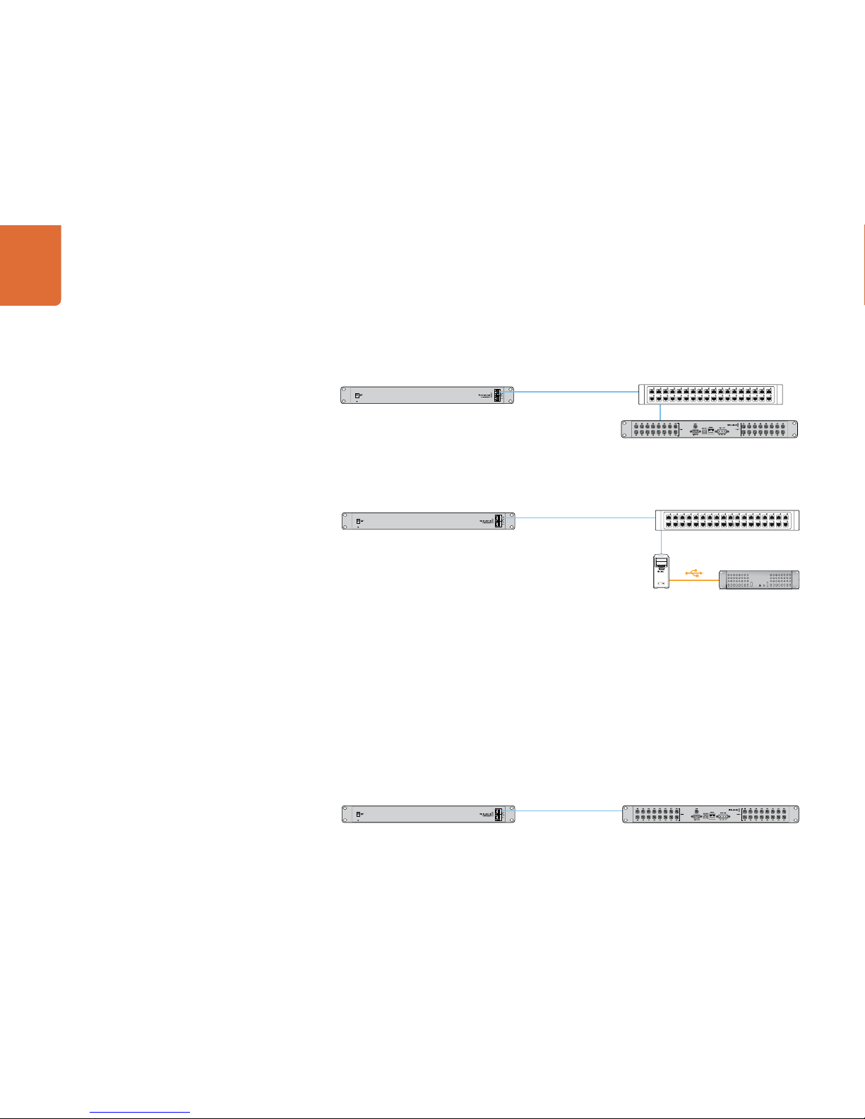
In most facilities, Videohub is usually shared via an Ethernet network switch so it can be controlled by
computers on the network as well as by Videohub control panels. See "Connection method 1".
Connection method 1. Connecting to an Ethernet-equipped Videohub via a network switch.
Videohubs without a built-in Ethernet port can be connected as shown in "Connection method 2".
Connection method 2. Connecting to a USB-attached Videohub via a network switch.
You might wish to connect your Videohub control panel directly to an Ethernet-equipped Videohub if:
• you need to set up very fast
• you don't have any requirement to share Videohub on the network so it can be controlled by computers
on the network
• you don't have much space, such as in an OB van
• you have a limited power budget, such as in an OB van
A regular Ethernet cable can be used between a Videohub control panel and the Videohub. There is no
need to use a special crossover cable. See "Connection method 3".
Connection method 3. Connecting directly to an Ethernet-equipped Videohub.
Videohub control panel connected via Ethernet networking Network Switch
Ethernet
Videohub connected via USBVideohub Server computer
Videohub control panel connected via Ethernet networking
Ethernet Videohub connected via Ethernet
Videohub control panel connected via Ethernet networking Network Switch
Ethernet
Videohub connected via Ethernet

Hardware Installation
11
When power is first connected to a Videohub control panel, a self-test will be conducted and all the buttons
will display their test lights in the following sequence: red, green, blue and white.
The top left button of a Videohub control panel indicates its network status, using the following diagnostic
display, as long as the panel is not selected in the Videohub Control Utility software:
Pink flashing light - unit is attempting to acquire an IP address. The button should quickly become
red if the unit is set to use a static IP address, or if the unit successfully acquires an IP address from the
DHCP server. If the button took several minutes before turning red, the unit has failed to acquire an
IP address and has eventually provided itself with a self-assigned AutoIP address in the 169.254.xxx.
xxx format. Unless you wish to use an AutoIP address, disconnect and firmly reconnect the network
cables to ensure they are properly connected, check for faulty network cables and make sure
the DHCP server has spare IP addresses available. Then unplug and reconnect all power sources from the
Videohub control panel so it will request a new IP address from the DHCP server. The button should quickly
become red.
Red flashing light - unit has acquired an IP address and is attempting to connect to the Videohub Server.
Make sure the Videohub Server is powered on and connected via Ethernet.
Yellow flashing light - unit has connected to a Videohub Server computer but the Videohub Server is
running an incompatible software or firmware version. Update Videohub with the latest version of Videohub
software and firmware and then power cycle the Videohub control panel.
No flashing light - unit has successfully connected to the Videohub Server and is ready to control the
Videohub if solid white, or solid white and gold, lights can be seen.
Hardware Installation
12
Connecting Videohub Control Panels with USB
Connecting Videohub Master Control with USB
A USB 2.0 connection to a computer is used to configure the network settings of Videohub Master Control.
When viewed from the rear of the unit, the type B USB port is easily found just to the right of the power
connector.
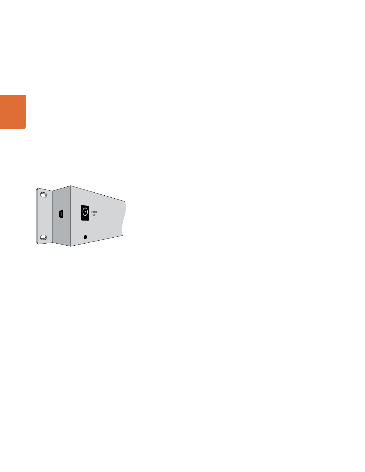
Connecting Videohub Smart Control with USB
A USB 2.0 connection to a computer is used to configure the network settings of Videohub Smart Control.
When viewed from the rear of the unit, the mini-B type USB port can be found on the small, left panel of the
chassis, just in front of the rack-mounting holes.
The USB port will become inaccessible once Videohub Smart Control has been installed in a rack. Therefore
most people will usually configure Videohub Smart Control via USB, and then remove the USB cable, before
installing the unit in a rack.
If you are likely to reconfigure Videohub Smart Control network settings periodically, then it may be more
convenient to permanently connect a USB cable to the unit before installing Videohub Smart Control in a
rack. This will enable Videohub Smart Control to connect to a computer via USB without needing to remove
the unit from the rack.
Side view of Videohub Smart Control showing the mini-B type
USB port
Hardware Installation
13
Labelling Control Panels
Videohub Master Control, Videohub Smart Control and Smart Videohub have removable face plates which
provide access to the buttons for labelling.
Included with the software installer is a Videohub Control Labels folder containing both PDF and Adobe
Illustrator template files. You can print and use either of these files for labelling the buttons. The Illustrator
file contains text boxes so you can add your text labels before printing them out. If you don’t have Adobe
Illustrator, you can just fill out and print the PDF file labels. Then cut out the square labels so they are ready
to be inserted in to the buttons.
To remove the face plate:
Step 1. Power off the unit and disconnect all cables.
Step 2. Remove the unit from the rack and lay it flat with the buttons facing upwards and the Ethernet
ports face-downwards on the table.
Step 3. Using a No. 2 Phillip’s head screwdriver, remove the 8 screws found on the top and bottom sides
of the faceplate.
Step 4. Now gently lift the face plate off the rest of the unit. If you have a Videohub Master Control, take
care not to pull on the data cable that connects the scroll wheel to the rest of the unit. The cable
is long enough to allow the face plate to lie down next to the rest of the unit.
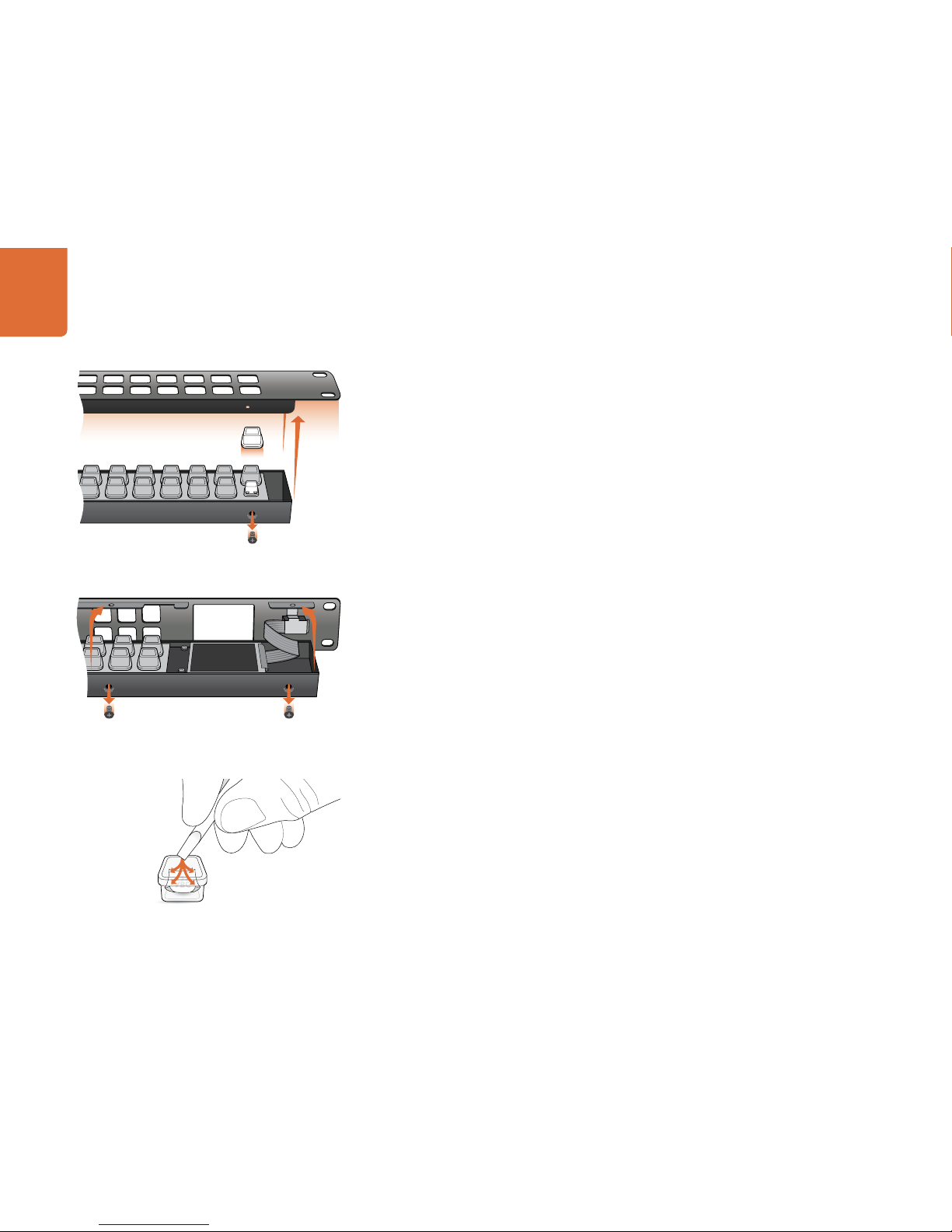
Step 5. The button caps can be easily lifted off with your fingers. Remove the clear cap from a button that
you wish to label, while taking care to avoid lifting the silicon button membrane.
Step 6. Loosely place the printed label into the upturned clear cap.
Step 7. Use a pointy device, such as the tip of a screwdriver, to lightly press the four corners of the square
paper label into the four, rounded corners of the clear cap. Avoid using a pen for the pointy device
as it is likely to mark your labels.
Step 8. Reinstate the clear cap containing the printed label. As the clear cap is pressed down on to its
silicon button, the paper label will be pushed forward, and neatly held flat against the window of
the clear cap. Repeat for as many buttons as you wish to label.
Step 9. Lower the face plate back into position, making sure the Blackmagic Design logo is the correct
way up. If you have a Videohub Master Control, make sure the data cable tucks neatly in to place.
Step 10. Replace the eight screws.
For Videohub Smart Control and Smart Videohub, remove the
8 screws, lift off the face plate and then the button caps.
For Videohub Master Control, remove the 8 screws, lift off the
face plate and carefully allow the face plate to lie down next to
the rest of the unit. Then remove the button caps.
Step 7. Lightly press the four corners of the square label into the
rounded corners of the clear cap
Software Installation
14
Installing the Videohub Control Utility Software
The Blackmagic Videohub Control Utility software is used to configure settings in Videohub Master Control
and Videohub Smart Control. Videohub Control Utility runs on the latest Lion and Mountain Lion versions of
Mac OS X. On the Windows platform, Videohub software runs on both 32 and 64-bit versions of Windows
7 with the latest service packs installed. Testing on previous versions of these operating systems is not
conducted and so it is always best to keep up to date with the latest versions of Mac OS X and Windows.
The Blackmagic Videohub Control Utility software only needs to be installed on one computer running Mac
OS X or Windows.
While the CD supplied with some models of Videohub contains the software installer, we recommend
you visit www.blackmagicdesign.com to ensure you have the latest version.
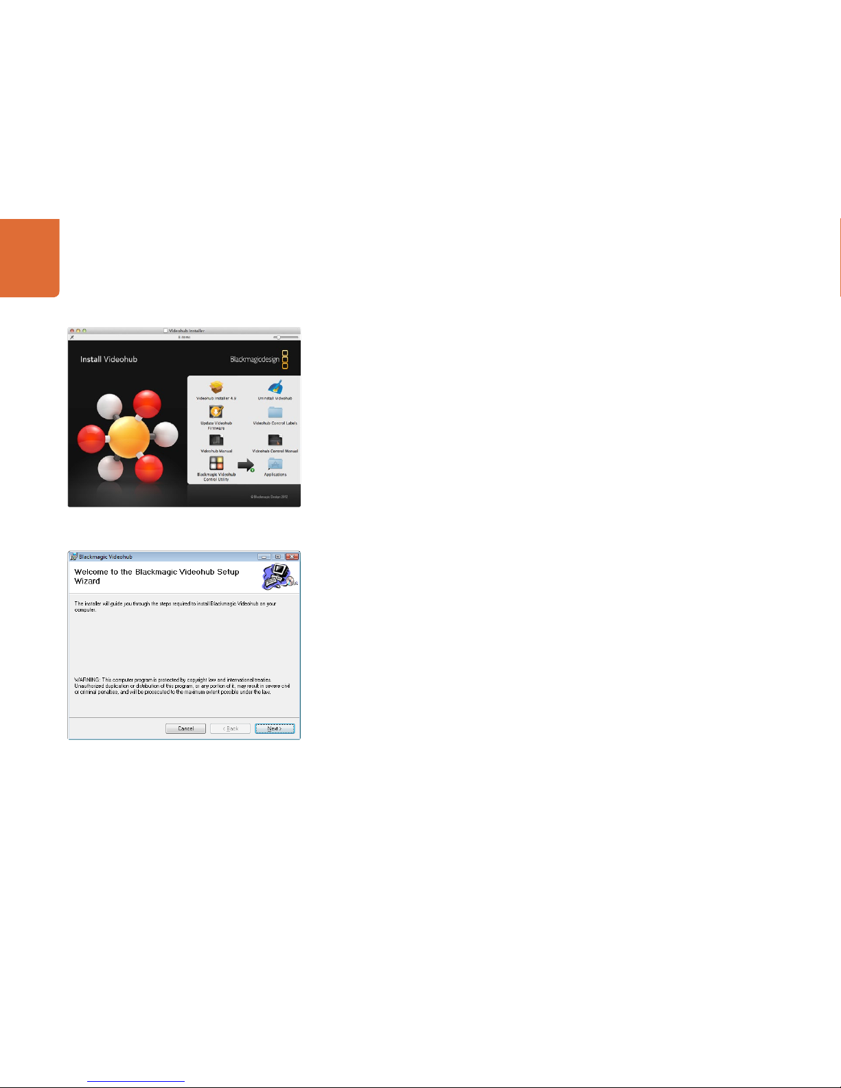
On Mac OS X, open the supplied CD, or downloaded disk image, and drag the Blackmagic Videohub
Control Utility to your Applications folder.
The Videohub software installer for Windows also installs the Blackmagic Videohub Control Utility and there
is nothing more you need to install. If you have not already installed the latest version of the Videohub
software for Windows, you will need to conduct the following steps.
Locate the installer file and double-click it. This will be on the supplied CD or, if downloaded
from the Blackmagic website, in your downloads folder. A dialog will appear saying, “Found new hardware”
and the Hardware Wizard will start. If prompted to search the Windows Update Website, select, “No, not
at this time” and click “Next”.
Select “Install the Software Automatically” and the system will find the Videohub control panel drivers
for you.
A “This software has not passed logo certification” or “The publisher could not be verified“ warning may
reappear during this process. Choose to “Continue Anyway” or “Run“.
Once this is complete and your Videohub control panel is connected and powered on, you are ready to
configure the device for your facility.
Windows installation: Follow install prompts.
Mac OS X installation: Drag the Blackmagic Videohub Control
Utility to the Applications folder

Software Installation
15
Updating the Software in Your Videohub Control Panel
Once the software installation has been completed and your Videohub control panel is powered on, it is a
good idea to check that the internal software is up to date.
Step 1. Launch the Blackmagic Videohub Control Utility.
Step 2. Connect your Videohub control panel to the computer via USB 2.0.
Step 3. If no software update is required, you will simply see the settings used by your Videohub control
panel. Settings can be changed now if desired and this is a good opportunity to give each
Videohub control panel a unique name. Please skip the rest of the steps in this section as your
Videohub control panel is already up to date.
If a software update is required, the following message will appear: "Software Update Required. The
software on this Videohub Control is out of date. Would you like to update it now?" Click Yes. The update
will take about 2 minutes to complete.
Step 4. The message, "Software Update Complete," should appear at completion of the update. Click
OK to dismiss the message. Settings can be changed now if desired and this is a good opportunity
to give each Videohub control panel a unique name.
Step 5. You can now unplug the USB cable from your Videohub control panel.
This message will appear if a firmware update is required.
The update will take about 2 minutes to complete.
Blackmagic Videohub Control Utility application icon

Software Installation
16
Configuring the Videohub Control Utility Software
After installing the Videohub Control Utility software, launch Blackmagic Videohub Control Utility and it
should immediately search your network for any Videohub control panels. Any panels discovered on the
network will be listed in the Videohub Control Panels pane with an Ethernet network icon next to their
names. If several Videohub control panels are listed, but you don't know which one is which, select one of
them and then press the "Identify" button. This will cause all the buttons of the selected Videohub control
panel to flash white.
Select the name of the desired Videohub control panel and you will be able to change the panel name and
also the control settings for each Videohub control panel. Network settings will remain grayed out and can
only be changed via USB.
If no Videohub control panels are found on the network, some units might not have received an IP address
via DHCP and it will be necessary to manually configure each unit with appropriate network settings. To
do so, connect a Videohub control panel to your computer via a USB 2.0 cable and launch Blackmagic
Videohub Control Utility. If the utility prompts you to update the software, refer to the previous section
named "Updating the Software in Your Videohub Control Panel". The USB-connected panel will be
automatically selected in the Videohub Control Panels pane and will show a USB icon next to its name. You
will be able to change all name, network and control settings for the USB-connected unit. After you have
finished configuring the unit, the USB cable can be removed.
The Blackmagic Videohub Control Utility automatically searches your network for any Videohub control panels. Two panels
have been found in this picture.
Any USB-connected panels will be listed in the Videohub Control
Panels pane with a USB icon.
Any panels discovered on the network will be listed in the
Videohub Control Panels pane with an Ethernet network icon.

Software Installation
17
If a Videohub control panel is selected in the Videohub Control Utility software, all of the panel's buttons will
illuminate with the same colors and intensity as shown in the software interface. While the panel is selected
in the software, the top left button will not indicate the status of the unit.
After configuring the network and control settings in the Blackmagic Videohub Control Utility, quit the
software or unplug its USB connection. If the top left button begins to flash, refer to the diagnostic light
information in the previous section named "Connecting Videohub Control Panels with Ethernet." Otherwise,
you can immediately test the buttons as you program them and verify the SDI routes are valid.
Network Settings
Each Videohub control panel requires an IP address to communicate with Videohub via your IP network.
When configuring a Videohub control panel via USB, you can choose DHCP or Static IP. DHCP automatically
obtains all the network settings for your Videohub control panel and is the easier choice.
If you decide to use a static IP address, please ask your system administrator for a spare IP address to avoid
creating an IP conflict on your network. You will then need to complete the IP address, subnet mask and
gateway details for your Videohub control panel. A static IP address must be used if directly connecting a
Videohub control panel to an Ethernet-equipped Videohub without using a network switch.
You will also need to complete the IP details for the Remote Videohub which you wish to control with your
Videohub control panel. The remote Videohub is the Videohub Server and could refer to a Videohub Server
computer or an integrated Videohub Server.
Add Videohub Control
If you already know the IP address of a Videohub control panel but it hasn't automatically appeared in the
Videohub Control Panels pane, you can add the Videohub Control manually. To do so, click Add Videohub
Control (+) at the bottom of the Videohub Control Panels pane. Type in the IP address of the Videohub
control panel and click OK. The software will verify the presence of the panel and add it to the Videohub
Control Panels list. If the Blackmagic Videohub Control Utility does not find a Videohub control panel at the
specified address, it will not add the unit to the list and will instead present an error message. You can use
Blackmagic Videohub Control Utility to manually add a Videohub control panel when connected to a panel
via Ethernet or USB.
Load/Save Settings
If you want to back up settings you've configured for your control panel, or set up several units the same way,
you can save the settings from an already configured Videohub control panel and then load the settings
file into the other units. After loading the pre-configured settings, you need only update network settings,
including the control panel name, for each unit. If you want to dedicate Videohub Smart Control units to
individual SDI destination devices, you will also need to specify the SDI destination device for each panel.
You can load and save settings by choosing “Load Settings” or “Save Settings” from the File menu.
Blackmagic Videohub Control Utility network settings
You can manually add a Videohub control panel, by IP address, to
the list of Videohub Control Panels

Software Installation
18
Videohub Master Control Settings
The right hand pane of the Videohub Control Utility software lets you customize the hardware features of
each Videohub control panel.
Backlight
Adjust the backlight slider as desired to vary the brightness of all backlit buttons.
How to Label Buttons in Videohub Master Control
15 of the pushbuttons can be labelled to provide fast selection of common equipment types, e.g. cameras,
VTRs and monitors. If you intend to solely use source and destination port numbers to select crosspoint
routes, it is unnecessary to label these buttons as you can simply use the pre-labelled numeric buttons.
If you prefer to use intuitive names of equipment to select crosspoint routes, you'll need to standardize
port labels before labelling any Videohub Master Control buttons. To standardize port labels, open the
Blackmagic Videohub application, go to the Blackmagic Videohub menu and choose Customize Labels.
In the example pictured below, several groups of equipment have been created by standardizing labels and
the remote port labels have been made the same as the associated inputs and outputs.
You can adjust the brightness of all backlit buttons in Videohub
Master Control

Software Installation
19
You should now standardize your labels for inputs, outputs and remote ports. For example, if you have
several video decks, you could label their inputs and/or outputs as HDCAM VTR, DVCPROHD VTR, DIGIB
VTR and so on. Alternatively you might want to list equipment by location. For example, all the equipment
in Studio 3 could have a "3" in its name, e.g. VTR 3, Cam 3A, Cam 3B, Mon 3A and Mon 3B. If you have an
RS-422 deck control connection to any of these decks, make sure the label for the RS-422 remote port is the
same as the corresponding label for the deck's input and/or output. Once you have finished standardizing
port labels in Blackmagic Videohub software, click the OK button.
You are now ready to label the Videohub Master Control buttons. Open the Videohub Control Utility and
select your Videohub Master Control from the Videohub Control Panels pane.
Click one of the 15 unlabelled buttons in the picture of the panel that appears in the top pane. Enter a text
label so it partially matches labels of SDI and deck control ports in the “Customize Labels” window of the
Blackmagic Videohub software. In this example, the label is “VTR” which will help to find all inputs, outputs
and remote ports which include VTR in their label name. Click OK and continue labelling the other buttons
as desired. You'll also want to create paper labels for the corresponding button caps on the Videohub
Master Control hardware.
Click on the desired button to edit its label.
Edit the button label to partially match labels you have given to
SDI and remote deck control ports in the “Customize Labels”
window of the Blackmagic Videohub software.
Software Installation
20
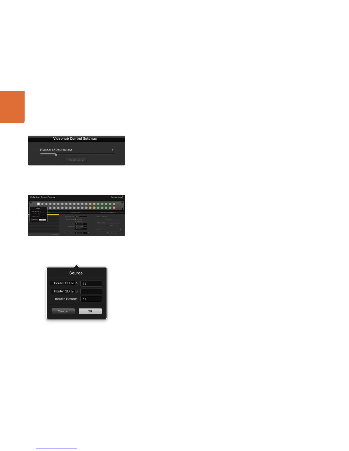
Blackmagic Videohub Smart Control configured with
multiple destinations.
Click on the desired Source or Destination button
to configure the button.
Videohub Smart Control Settings
The right hand pane of the Videohub Control Utility software lets you customize the hardware features of
each Videohub control panel.
Number of Destinations
Videohub Smart Control can be configured as a Cut-Bus controller or as an XY controller.
When configured as a Cut-Bus controller, every button represents an SDI source and there is only one
destination. Use this configuration when dedicating a Videohub Smart Control unit to a single destination
device, such as an SDI monitor or deck. All of the buttons will become white to indicate that they are all
source buttons. Simply slide the “Number of Destinations” slider all the way to the left so the number of
destinations becomes “1”. The “Destination” button below the slider will become active. Click on the active
“Destination” button and enter the number of the Videohub output port, to which the destination device
is connected, in to the “Router SDI Out A” field. If your destination device is receiving dual-link HD-SDI
or dual-stream 3D, you will also need to enter an output port number in to the “Router SDI Out B” field.
There is also a “Router Remote” field if your Videohub is also routing RS-422 deck control to the destination
device. Click “OK” to confirm the Destination settings.
When configured as an XY controller, Videohub Smart Control can be configured to work with up to 20
destinations. The source buttons will illuminate white and the destination buttons will illuminate gold-colored.
Use this configuration if you don’t intend to dedicate a Videohub Smart Control unit to each destination
device. Simply slide the “Number of Destinations” slider to the right so the number of destinations increases
to the desired number. The “Destination” button below the slider will become grayed out and inactive. You
can now configure the destination buttons by clicking on each gold button in the software interface. Enter
the number of the Videohub output port, to which the destination device is connected, in to the “Router
SDI Out A” field. If your destination device is receiving dual-link HD-SDI or dual-stream 3D, you will also
need to enter an output port number in to the “Router SDI Out B” field. There is also a “Router Remote”
field if your Videohub is also routing RS-422 deck control to the destination device. Click “OK” to confirm
the destination settings. If you increase the number of destination buttons, there will be a corresponding
decrease in the number of available source buttons.
Source buttons are configured in much the same way as destination buttons by clicking on each white
button in the software interface. Enter the number of the Videohub input port, to which the source device is
connected, in to the “Router SDI In A” field. If your destination device is receiving dual-link HD-SDI or dual-
stream 3D, you will also need to enter an input port number in to the “Router SDI In B” field. There is also
a “Router Remote” field if your Videohub is also routing RS-422 deck control from the source device. Click
“OK” to confirm the source settings.
Enter the number of the Videohub port to which the SDI device
is connected.
This manual suits for next models
1
Table of contents


