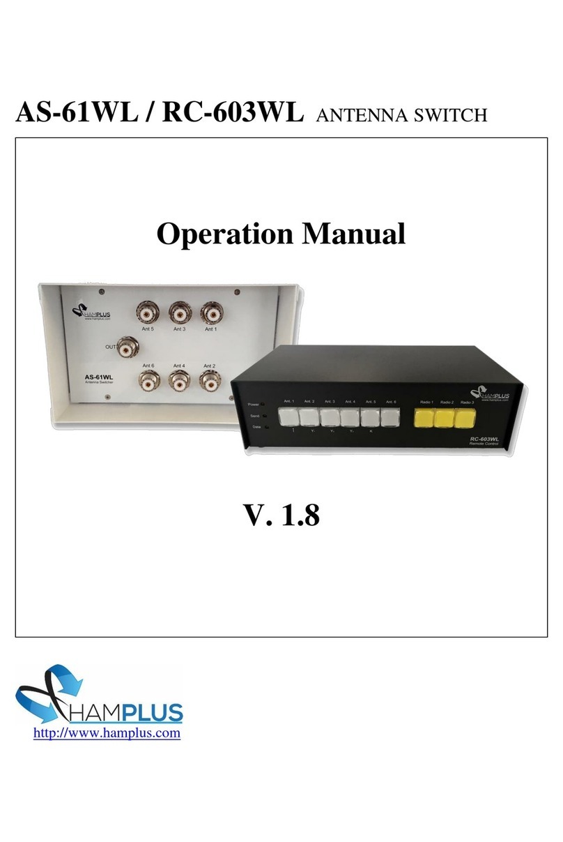
Hamplus AS-603UR User manual

AS-603UR –Operation Manual Page 1
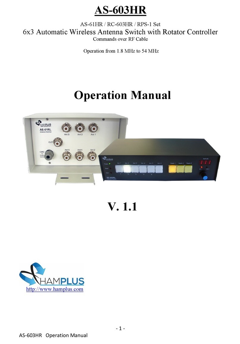
AS-603UR
AS-61VR / RC-603VR/RPS-1 Set
6x3 Automatic Wireless Antenna Switch with Rotor Controller
The AS-61VR /RC-603VR /RPS-1 set is an automatic antenna switch for three
Radios, six Antennas and control for two Rotators. There are three independent boxes,
the AS-61VR for changing antennas, which is close to antennas, and the RC-603VR with
the Push Buttons for the selection of the antennas and Radios, and the control of the
Rotators with a three-digit Display, an Encoder and two LEDs, which is close to the
Radios. The third box, RPS-1, is for driving the two Rotors. The RPS-1 receives the
activation commands from the AS-61VR and the power from an external 110/220 VAC
source. The connection between the AS-61RL and the RC-603VR is made only by the RF
cable (RG-58 or RG-213). This cable takes RF and the necessary commands for the
perfect operation of this system. The operation is individual, this means that only the
selected radio will have access to the Antennas and Rotators. Unused antennas are
automatically shorted.
To facilitate the operation, the RC-603VR has an internal switch that switches the
Send command and the Com port to the selected Radio.
The AS-603UR supports communication with the following radios:
Icom (CI-V), Kenwood (RS-232), Elecraft K3 (RS-232), Yaesu (RS-232), Flex Radio (RS-
232) or any other Radio that uses one of these communication protocols.
Procedure for connecting the RC-603VR to the radio:
1- On the RC-603VR press and hold the yellow radio select Push button and turn on
the RC-603VR.
2- Then press the Antenna Push Button corresponds to the model of the radio that
you will connect, according to the list below;
a- Ant 1 Push Button for Icom (CI-V) radios Baud rate 19200
b- Ant 2 Push Button for Yaesu type FT-817, FT-857 and others. Baud rate 4800
c- Ant 3 Push Button for Yaesu type FT-1000 MP radios and others. Baud rate 4800
d- Ant 4 Push Button for Yaesu type FT-5000 radios and others. Baud rate 4800
e- Ant 5 Push Button for Kenwood, Elecraft, Flex Radio, and others. Baud rate 4800
After the choice, the Split/Data LED stops blinking, this indicates the end of this
procedure.
Procedure to activate Split mode:
To activate Split mode, the RC-603VR must be connected to the radio with the
appropriate cable and the TX Delay of the radio must be set to 20 ms or more.
1- Press the PTT on the radio and watch the RC-603VR's Send LED light up.
2- Then, with the PTT still pressed, press and release the button of the antenna that
you want to receive.
3- When PTT is released, the RC-603VR will switch to the chosen receiving antenna.

AS-603UR –Operation Manual Page 2
Each time you press the PTT, it returns to the transmitting antenna.
Any change of antenna or band on the radio deactivates Split mode.
Testing and using the automatic antenna selection feature of the RC-603VR/AS-61VR
with a connected and selected radio:
NOTE: No computer programming, PC connection or internal changes are required. A
connected radio means that it is interfaced to the RC-603VR with a cable, such as
Hamplus ERC-6, IRC-6, KRC-6, YRC-6, FRC-6 or YRC-61, and the radio set to the correct
baud rate (19,200 baud CI-V or 4800 baud CAT and COM) and set up as described in the
previous section.
If the RC-603VR is not interfaced as described, then it may be operated as a Manual
Antenna Switch.
When connected, the RC-603VR is an Automatic Band Memory Antenna Switch that may
be operated manually. “Programming” automatic antenna selections are made as each
different band is selected on the connected and selected radio. The initial manual
selection of a specific antenna for that band is made by depressing the desired Ant
button, which is then automatically memorized. There is no “SAVE” button nor is there a
multi-button programming sequence. Just set the antenna by the band on the radio.
Restated, simply assign or reassign any RC-603VR Ant button number to any band by
initial or subsequent manual selection. For every and any band chosen and displayed on
the connected and selected radio, every time a different antenna button is manually
depressed, that selection is memorized.
Here is an example of antenna memorization by band setting on the transceiver
connected to and selected as Radio 1 on the RC-603VR:
1. Select 40 meters on Radio 1 and press Ant 2 on the RC-603VR (as if your 40
meters antenna is connected to the Ant 2 port on the AS-61VR)
2. Select 80 meters on Radio 1 and press Ant 1 on the RC-603VR (as if your 80
meters antenna is connected to the Ant 1 port on the AS-61VR)
3. Select 20 meters on Radio 1 and press Ant 3 on the RC-603VR (as if your 20
meters antenna is connected to the Ant 3 port on the AS-61VR), and so on.
Now, test the automation by changing back to the 40 meters band on your radio.
The RC-603VR should now automatically switch to Ant 2.
Then, select 80 meters on your radio and the RC-603VR automatically switches
to Ant 1, and so on.
If automatic antenna selection by band or frequency does not occur, then reattempt the
Procedure for connecting the RC-603VR to the radio in the section above.
Supporting the use of a multi-band antenna, the RC-603VR provides the ability to assign
any single antenna port to any number of bands on the connected radio, also by initial
manual selection.

AS-603UR –Operation Manual Page 3
For example: A 20/15/10 meters tri-band beam coaxial cable is connected to Ant 3 port
on the AS-61VR.
4. Select 20 meters on the connected radio and press Ant 3 on the RC-603VR
(because your tri-band antenna is connected to Ant 3 port on the AS-61VR)
5. Select 15 meters on the connected radio and press Ant 3 on the RC-603VR
(because your tri-band antenna is connected to Ant 3 port on the AS-61VR)
6. Select 10 meters on the connected radio and press Ant 3 on the RC-603VR
(because your tri-band antenna is connected to Ant 3 port on the AS-61VR)
Now, test the tri-bander automation by selecting any of those bands, 20, 15
and 10 meters, on your radio. The RC-603VR will now automatically stay on
Ant 3, or go back to Ant 3 after selecting a band with a different band
memorized.
7. Select 80 meters on your radio and the RC-603VR automatically switches to
Ant 1,
8. Then, select 20 meters on your radio and the RC-603VR automatically
switches back to Ant 3… and so on.
IMPORTANT FEATURE: PC interface to this antenna switch controller is not necessary.
Interfaced transceivers that are also controlled locally or remotely by USB or LAN will
continue to benefit from this Automatic Band Memory Antenna Switch. This smart
controller method of automatic antenna selection is simply made by band or frequency
selection with the radio control program.
REMINDER: Reassignment of any band or frequency to a different antenna port is simply
made by manual reselection of the new antenna port number whenever the connected
radio is set on that specific band or frequency. The manual change is automatically
updated by the RC-603VR for only the selected radio. Simply stated, reassign any Ant #
to any band by manual reselection of the new Ant # whenever the radio is set to that
band.
For example, let’s say that you now want to move your 40 meters antenna to the Ant 5
port on the AS-61VR. Simply select 40 meters on the connected radio and press Ant 5
on the RC-603VR, and it memorizes this change. Each time you change this radio to a 40
meters frequency, Ant 5 will now be automatically selected.
NOTE: On any given radio band, any manual antenna selection that is made,
even if it happens to be incorrect, will be memorized. So, check and recheck each
of your band memorized antenna selections by changing to each of the bands on
your connected and selected radio and watching the RC-603VR automatically
change to the correct antenna. Correct any wrong Ant # on any band by manual
selection.

AS-603UR –Operation Manual Page 4
Rotor Operation:
Introduction:
The RC-603VR's Rotator Controller consists of a three-digit Display to indicate
the azimuth of the antenna in use, an Encoder to choose the new azimuth and two LEDs
to indicate the Rotor that is in use.
Each of the six antennas can be associated with either or both Rotators. This way,
when an antenna is selected, the Rotor associated with it is also selected and its
azimuth is indicated on the Display. When you want to change the azimuth of the
antenna you just need to turn the Encoder until you see the new azimuth on the
Display. The Display also shows the movement of the antenna until it reaches the new
chosen azimuth.
Initial settings:
The first task to be done is to calibrate the Rotator. It aims to synchronize the
position of the Rotator with the indication of the Display.
1- Rotator calibration:
Calibration is a simple task that must be done before placing the Rotator on the
tower. Before starting the calibration, connect all cables between the parts involved.
Start by connecting the Rotators to the RPS-1, this one to the AS-61VR, and this
through an RF cable to the RC-603VR control. Also connect the RPS-1 to the power
source.
a- First step- Switch on the RC-603VR with the Encoder button pressed. Wait with
the Encoder pressed until the Display shows 0 0 0 then release the Encoder. At
this point, the Display will show C A L indicating that you are in the Rotator
calibration mode. The Display will be showing C A L throughout the calibration
procedure.
b- Second step- Choose which Rotator to be calibrated. For Rotator 1, turn the
Encoder counterclockwise (ccw) until the Rotator 1 indicator LED lights up. For
Rotator 2, turn the encoder clockwise (cw) until the Rotator 2 indicator LED
lights up.
c- Third step- Position the rotator at the starting point of the stroke. Press the
Encoder momentarily. At this point, the Rotator will begin to rotate until it finds
the starting point of the rotator stroke. Then he stops the Rotator and turns on
the Ant4 button and Ant6 button.
d- Fourth step- Position the Rotator at the end of the stroke. Now you must create
a reference point for this Rotator position, with the greatest possible precision,
so you will rotate the Rotator clockwise (cw) in one complete revolution (360
degrees) using the Ant6 (cw) button and Ant4 (ccw) button until it reaches
exactly the point where the Rotator started the turn. This is the end point of the
Rotator stroke.

AS-603UR –Operation Manual Page 5
e- Fifth step- Finish the calibration. After the start and end of the stroke are
marked, momentarily press the Encoder. The Display stops showing C A L and
starts showing the Rotator position, (1 8 0). Rotator calibration is complete.
f- Sixth step- Install the Rotator on the tower. Now with the Rotator calibrated you
can place it on the tower.
2- Antenna alignment:
After calibrating the Rotator, you can place it on the tower and install the
antenna.
Suggestion for antenna alignment:
Adjust the Rotator position to the North, placing 0 0 0 degrees on the Display.
Then place the Antenna towards the North and fix it on the Rotator. Do not
forget the magnetic declination, as the Antenna must be pointed towards the
true North. So, the display indication will always be the correct direction of the
Antenna.
3- Choice of Rotator for the antenna:
The RC-603VR can control up to two Rotators. This procedure is for
associating an antenna to a Rotator. So, when you select the antenna the
controller will be connected to the Rotator of this antenna, the LED indicator of
the Rotator in use will be illuminated and the Display will indicate the position of
the antenna.
a- First step- Enter the Rotator choice mode. Press the Ant button for five seconds.
At this moment the Ant6 button starts to flash and the Ant1 and Ant2 buttons
are available to choose Rotator1 or Rotator2 respectively.
b- Second step- To choose the Rotator. For Rotator 1 press the Ant1 button, for
Rotator 2 press the Ant2 button. When the button is pressed it is illuminated
and LED RT1 or LED RT2 is also illuminated, indicating the chosen Rotator.
The RT1 and RT2 LEDs off indicate that the Antenna is not connected to any
Rotator and the Display indicates O F F.
c- Third step- Save and exit. To save and exit, press the flashing Ant6 button.
4- Start and end of course, North or South:
The RC-603VR's Rotator controller has the default to indicate the
beginning and end of the Rotator stroke at 1 8 0 degrees, which represents the
South position.
This position can be switched to indicate 0 0 0 degrees, which represents the
North position.
To change the indication
a- First step- Press the Encoder for five seconds. At this moment the buttons
Ant1, Ant2, Ant3, Ant5 and Ant6 start to flash.
b- Second step- To change the indication, press the Ant5 button.
To abort the procedure, press the Ant6 button.

AS-603UR –Operation Manual Page 6
Important: If the antenna is already installed you will have to make a new alignment
because the new indication on the Display will be 180 degrees out of step with the old
one.
5- Rotator stroke limit:
In some installations, such as on the side of a tower, the antenna cannot
rotate 360 degrees because it encounters obstacles. For these cases, the RC-603VR
Rotator controller has the Stroke Limit function.
Counterclockwise limit (CCW)
a- First step- Position the antenna at the limit of the counterclockwise (CCW)
direction. Do not let the antenna touch the obstacle, leave a small gap.
b- Second step- Save the counterclockwise limit point (ccw). After performing the
first step Press the Encoder for five seconds. At this moment the buttons Ant1,
Ant2, Ant3, Ant5 and Ant6 start to flash. Press the Ant1 button to save the limit
counterclockwise (ccw) or press the Ant6 button to abort this procedure.
To clear the limits, press the Ant2 button.
Clockwise Limit (CW)
a- First step- Position the antenna at the clockwise limit (CW). Do not let the
antenna touch the obstacle, leave a small gap.
b- Second step- Save the clockwise limit point (cw). After performing the first step,
press the Encoder for five seconds. At this moment the buttons Ant1, Ant2,
Ant3, Ant5 and Ant6 start to flash. Press the Ant3 button to save the limit
clockwise (cw), or press the Ant6 button to abort this procedure.
To clear the limits, press the Ant2 button.
Applicable rotor types:
The Rotators that can be used with this controller are those with a 24 VDC motor
and the direction indicator is a 500 Homs one-turn potentiometer, or a 10K Homs 10-
turn potentiometer. Like Yaesu G800, G1000, G2800, Special Engine, Prosistel and
others.
-----------------------x----------------------

AS-603UR –Operation Manual Page 7
1- Antenna selection buttons
2- Radio selection buttons
3- Azimuth indicator display
4- Power On LED indicator
5- Split Antenna LED indicator
6- Send indicator LED
7- Rotor 1 indicator LED
8- Encoder button
9- Rotor 2 indicator LED

AS-603UR –Operation Manual Page 8
1- Auxiliar Power Supply In 8- Control Cable to Radio 3
2- Switched Send Relay Out 9- Control Cable to Radio 2
3- Send Radio 3 10- Control Cable to Radio 1
4- Send Radio 2 11- RS-232 Remote Control Com
5- Send Radio 1 12- RF from Radio 1
6- RF from Radio 2 13- RF from Radio 3
7- RF Out to AS-61VR 14- GND

AS-603UR –Operation Manual Page 9

AS-603UR –Operation Manual Page 10
Diagram of blocks and connections of the antenna switch AS-603UR without the rotator
power supply module, mounted in two cabinets
Cabinet 1 contains the RC-603VR controller
Cabinet 2 contains the AS-61VR antenna switch

AS-603UR –Operation Manual Page 11
Diagram of the blocks and connections of the antenna switch AS-603UR with the rotator
power supply module, mounted in three cabinets
Cabinet 1 contains the RC-603VR controller
Cabinet 2 contains the AS-61VR antenna switch
Cabinet 3 contains the RPS-1 rotator power supply

AS-603UR –Operation Manual Page 12
Diagram of blocks and connections of the antenna switch AS-603UR with the rotator
power supply module, mounted in two cabinets
Cabinet 1 contains the RC-603VR controller
Cabinet 2 contains the antenna switch and the rotator power supply AS-61VRP

AS-603UR –Operation Manual Page 13

AS-603UR –Operation Manual Page 14

AS-603UR –Operation Manual Page 15

AS-603UR –Operation Manual Page 16

AS-603UR –Operation Manual Page 17

AS-603UR –Operation Manual Page 18

AS-603UR –Operation Manual Page 19
This manual suits for next models
3
Other Hamplus Switch manuals