1809 Century Avenue, Grand Rapids, Michigan 49503-1530, U.S.A.
Telephone: (616) 241-1611 / Fax: (616) 241-3752 109-A00
OIL SEAL REPLACEMENT
1. To replace the oil seal (104A) on the input shaft, it is only
necessary to remove the closure plate (114). Once the
plate is removed, the old seal can be pressed out and a
new one installed. Grease the lip of the oil seal before
installing. The oil seal must be inserted such that the lip of
the seal will face inward when the closure plate is
reattached to the gearcase cover.
2. To replace the two (2) oil seals (104) on the output shaft,
it is necessary to disassemble the body and cover
assembly and remove the output shaft. (Refer to “Reducer
Disassembly.”) Grease the lip of one oil seal and insert it
into the bearing bore of the gearcase so that the lip of the
seal faces inward. Install the spacer ring (82A) and insert
the second oil seal also with the lip facing inward.
REDUCER ASSEMBLY
Before reassembling the gear reducer, clean each part
thoroughly. Wash out the bearing bores and remove all burrs
or sharp corners with a file.
NOTE: Disregard steps 1 and 2 if the shaft and bearing
assemblies have not been dismantled.
1. The output shaft (125) has a stepped shoulder on one end
(retaining ring end) to facilitate bearing and gear location.
a. Before installing the gear and bearings, remove all
dirt, burrs, or sharp corners from the shaft to prevent
galling or seizing of the gear and shaft.
b. Apply a coat of graphite, molysulphide, or white lead
to the shaft.
c. Press the retaining ring end of the shaft squarely into
the shielded bearing (24B). The shield of the bearing
should be upward, so that the balls of the bearing will
face the gear.
d. Install the spacer ring (82).
e. Align the gear key (124) with the notch in the gear
(101), and press the gear squarely onto the shaft.
Install the other spacer ring (82).
f. Press the second bearing (24C) squarely onto the
shaft and add the retaining ring (83).
2. To assemble the input shaft (102) (Pinion & Shaft) a
bearing must be pressed onto each end of the shaft.
a. Prior to installing the bearings, follow steps 1a and 1b.
b. Press the shielded bearing (24A) onto the driven end
of the shaft (longer end) with the shield facing
downward so that the balls of the bearing will face the
pinion.
c. Press the second bearing (24) onto the opposite shaft
end.
3. After the shafts, gears and bearings have been
assembled, apply a light film of oil in the bearing bores of
the gearcase to help the bearings slide into position.
4. If the oil seals (104) have been removed from the
gearcase, they must be replaced prior to reassembly.
Refer to step 2 of “Oil Seal Replacement.”
5. To install the shaft assemblies into the gearcase it is
easiest to tip the gearcase so that it is resting on the
closed end, with the cavity opening upward.
a. Start the output shaft (125) into the bearing bore of the
gearcase.
b. Align the bearings and gear teeth of the input shaft
(102) with the output shaft and drop the two shaft
assemblies together into their respective bearing
bores.
NOTE: It is important to line the bearings up squarely
with the bores in order for them to drop smoothly into
place. If the bearings are positioned correctly in the
gearcase, the shafts should rotate freely when turned
by hand.
6. Once the input and output shaft assemblies are properly
installed, set the cover gasket (111) on the gearcase.
7. Position the cover on the gearcase using the dowel pins
for alignment.
8. Install and tighten the cover capscrews (112).
9. Make sure the oil seal (104A) is inserted in the closure
plate (114) before reattaching the plate to the gearcase
cover. Refer to step 1 of “Oil Seal Replacement.”
10. Set the closure plate gasket (115) and the closure plate
(114) on the gearcase cover. Install and tighten the
remaining two (2) cover capscrews (112A), and the five
(5) closure plate capscrews (116).
TROUBLESHOOTING
NOISE AND VIBRATION
POSSIBLE CAUSES: REMEDY:
1. Worn or damaged bearings. Replace bearings.
2. Inadequate lubrication / use of wrong lubricant. Check oil condition. The lubricant may not be getting to the
contact areas of the gear teeth, or the viscosity of the oil may be
too low for the operating temperature (see “Lubrication”).
3. Impurities in the lubricant, such as abrasive particles. Replace with clean oil (see “Lubrication”)
4. Excessive overloading.
Overloading causes overheating which may lower oil viscosity and
thus cause the oil film on gear teeth contact surfaces to break
down. The gears will begin to “groan” as the oil loses its
effectiveness. If the loading is not decreased, the gear teeth will
begin to “bite” into each other and wear out rapidly.
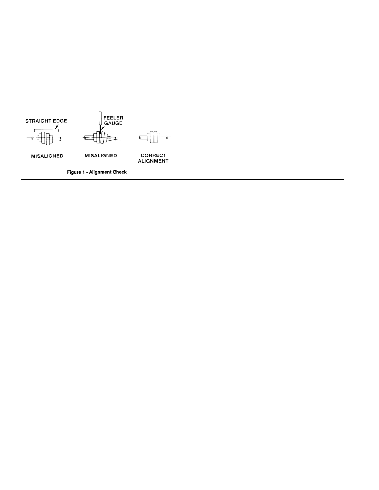
5. Misalignment to either pump or motor. Recheck alignment and adjust as necessary.