2
www.blaubergventilatoren.de
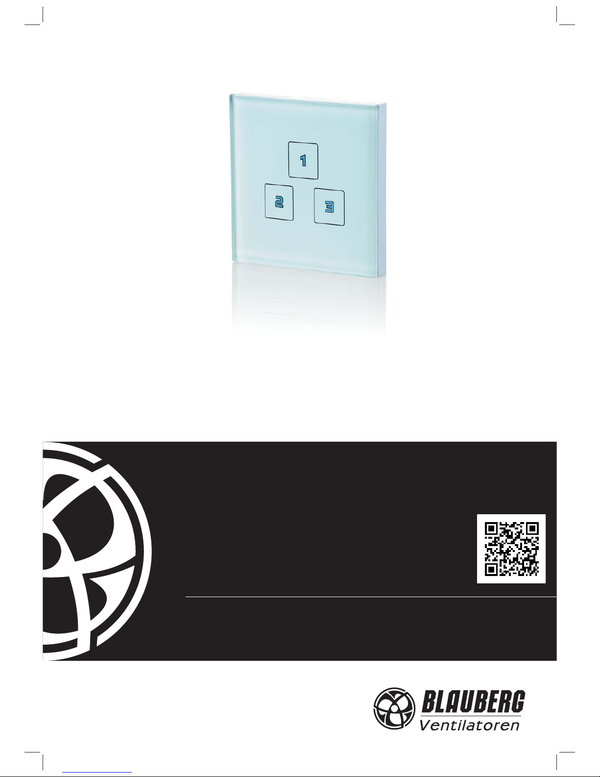
SGR-3/1
BLAUBERG Ventilatoren GmbH is happy to oer your attention the sensor
speed switch SGR-3/1.
INTRODUCTION
The present operation manual contains technical description, technical
data sheets, operation and mounting guidelines, safety precautions and
warnings for safe and correct operation of the speed switch.
Read carefully the operation manual, especially the safety requirements
before mounting and start-up of the device.
Keep the operation manual available as long as you use the device.
GENERAL
The sensor speed switch SGR-3/1 is designed for switching on/o and
speed switching of multi-speed ventilation units and domestic fans. The
speed switch is equipped with a sensor panel with three buttons for speed
selection.
SAFETY RULES
The speed switch complies with the requirements according to the EU
norms and directives, to the relevant EU-Low Voltage Equipment Directives,
EU-Directives on Electromagnetic Compatibility.
Cut o power supply to the speed switch prior to any operations.
All mounting and maintenance operations must be carried out by duly
qualied electricians with a valid electrical work permit for electric operations
after careful study of the present user’s manual.
Misuse of the speed switch or any unauthorized modication are not
allowed.
Follow the manual guidelines to ensure trouble-free operation and long
service life of the speed switch.
STORAGE AND TRANSPORTATION RULES
Transportation is allowed by any vehicle provided the speed switch is
transported in the original package and is protected against weather and
mechanical damages.
Store the delivered speed switch in the manufacturer’s original packing
box in a dry ventilated premise.
The storage environment must not be subjected to any aggressive and/
or chemical evaporations, admixtures, foreign objects that may provoke
corrosion and damage connection tightness.
Store the speed switch in an environment with minimized risk of
mechanical damages, temperature and humidity uctuations.
Store the delivered speed switch at the ambient temperature from +5°C
up to + 40°C.
MANUFACTURER’S WARRANTY
The speed switch complies with the requirements according to the EU
norms and directives, to the relevant EU-Low Voltage Equipment Directives,
EU-Directives on Electromagnetic Compatibility.
We hereby declare that the following product complies with the essential
protection requirements of Electromagnetic Council Directive 2004/108/
EC, 89/336/EEC and Low Voltage Directive 2006/95/EC, 73/23/EEC and
CE-marking Directive 93/68/EEC on the approximation of the laws of the
Member States relating to electromagnetic compatibility.
The manufacturer hereby warrants normal operation of the speed switch
over the period of 1 year from the retail sale date provided observance of the
installation and operation regulations.
In case of failure due to manufacturing fault during the warranty period
the consumer has the right for the speed switch repair or exchange.
The replacement is oered by the Seller.
If case of no conrmation of the sale date, the warranty period shall be
calculated from the manufacturing date.
The manufacturer shall not be liable for any damage resulting from any
speed switch misuse of or gross mechanical interference with the speed
switch.
The manufacturer is not responsible for the damages resulted due to the
use of third party equipment or to third party equipment.
DELIVERY SET
Sensor speed switch SGR-3/1;
Operation manual;
Packing box;
Fasteners.
WARNING
Do not dispose in domestic waste. The product
contains in part material that can be recycled and in
part substances that should not end up as domestic
waste. Dispose of the product once it has reached the
end of its working life according to the regulations valid
in your country.
WARNING
The speed switch is not allowed for use by children and persons with
reduced physical, mental or sensory capacities, without proper practical
experience or expertise, unless they are controlled or instructed on the
product operation by the person(s) responsible for their safety. Supervise
the children and do not let them play with the product.