Blaze ASI-5 User manual

Introduction
The ASI-5 is a 3 1/8” (80mm) sunlight readable instrument that pro ides a wide range airspeed indication in both digital
and analog tape formats. Airspeed is based on the pressure generated by a pitot tube system and a static port is pro ided
as well for use by high speed aircraft. In addition, the ASI-5 pro ides a flight timer since takeoff and records the maximum
airspeed reached.
Airspeed can be indicated in statute miles per hour (mph), kilometers per hour (km/h) or nautical miles per hour (kts). The
analog airspeed tape can be scaled according to the aircraft’s flying speed range and ranges for Vs0, Vs1, Vfe, Vno and
Vne can be set. The ASI-5 also pro ides a programmable Vs and Vne airspeed alarm output. ASI sensiti ity can be
calibrated by the user to cater for errors caused by pitot tube placement.
The ASI-5 can measure airspeed from 20mph to 250mph (Version 1), 20mph to 350mph (Version 2) and 20mph to
320mph for the ASI-5HS (High Speed ersion). All are well suited to slower aircraft due to ery good sensiti ity and
linearity at low air speeds.
Please note that the ASI-5 Version 2 replaces both the ASI-5 Version 1 and the ASI-5HS (High speed) unit.
Bla e ASI-5
Airspeed Indicator (ASI)
Operating Manual – English 1.06

Bla e ASI-5 Operating Manual Page 2
1 Features
•Large 2.6” high resolution 320x240, IPS (fully viewa le in all directions), sunlight reada le color LCD
display
• The ASI-5 measures airspeed from 20mph to 250mph (Version 1)
• The ASI-5 measures airspeed from 20mph to 350mph (Version 2)
• The ASI-5HS (High Speed version) measures airspeed from 20mph to 320mph
• Both units are well suited to slow aircraft due to very good sensitivity and linearity at low air speeds
• Includes a flight timer since takeoff
• Airspeed units can be set to miles per hour (mph), kilometer per hour (km/h) or nautical miles per hour
(kts)
• Analog tape with programmable ranges for Vs0, Vs1, Vfe, Vno and Vne
• Contains a programmable Vs and Vne airspeed alarm output
• Records maximum airspeed reached in permanent memory
• Includes a RS232 serial output for interfacing to external equipment e.g dataloggers etc.
• Standard 3 1/8” aircraft enclosure (can be front or rear mounted)
• The LED backlight can automatically adjust to the ambient light, or it can be manually adjusted in the
menu system
• Rotary control plus 2 independent buttons for easy menu navigation and user input
• Wide input supply voltage range of 8 to 30V DC with built in voltage reversal and over voltage protection
for harsh electrical environments
• 1 year limited warranty

Bla e ASI-5 Operating Manual Page 3
2 Layout
3 Main Display
The ASI-5 has 2 different display screens. The main display screen can be selected in the “ASI SETUP” menu.
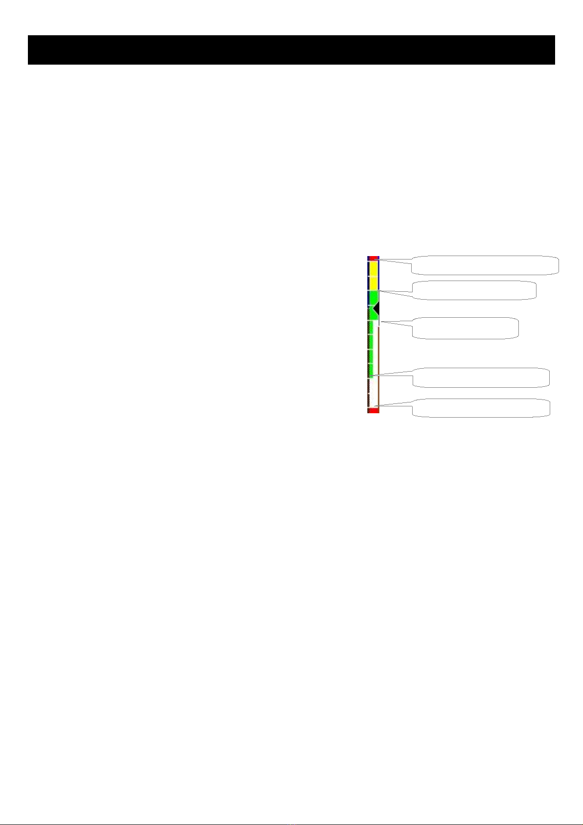
3.1 Airspeed "TAPE" Display
F2 / Down Button:
Menu system: Softkey button
Sunlight readable color graphic display:
The backlight can automatically adjust
to the ambient light or it can be manually
adjusted in the menu system
Rotary Control (Up/Down) & Enter Button:
Press the rotary control during the normal display screens to access the menu system. Rotate anti/clockwise for
up/down menu scrolling. Rotate the rotary control during the normal display mode to iew the Max Values display.
F1 / Up Button:
Menu system: Softkey button
Normal Display: Start / Stop the
flight timer (Manual flight only)
3 1/8” (80mm) enclosure.
Can be front or rear mounted
Airspeed unit
Digital airspeed
Airspeed tape
Duration of flight since takeoff
Vs0 (Min safe speed, landing)
Vs1 (Min safe speed, normal)
Vfe (Max flap speed)
Vno (Max maneu ering speed)
Vne (Max exceed speed)
Ambient light sensor

Bla e ASI-5 Operating Manual Page 4
3.2 Airspeed "DIAL" Display
3.3 Maximum Airspeed display
This display can be accessed by rotating the rotary control during the normal display
mode. Press the F1/Up button when the max alues display is showing to reset the
maximum alues to the current airspeed.
3.4 Start / Stop flight display
Press the F1/Up button during the normal display mode
to manually start/stop a flight. This key is only acti e if
the ASI-5 is setup to select the manual flight option
under the “TIMERS” setup menu.
Note: The maximum airspeed is stored in non-volatile
memory and is recalled on power-up.
Duration of flight since takeoff
Digital airspeed
Airspeed unit
Analog airspeed dial

Bla e ASI-5 Operating Manual Page 5
4 Menu System
Press the rotary control button during the normal display mode to enter the menu system. Use the rotary control to
na igate through the menu system.
4.1 Exiting the menu system
Press the F1/Up button to exit the menu system when the “EXIT” soft key is shown. All changes made during na igation
of the menu system will be sa ed in non- olatile memory upon exiting. The instrument will not sa e any changes if you
remo e power before exiting the menu system.

Bla e ASI-5 Operating Manual Page 6
4.2 Flight Timer
View Flight Log:
Use the rotary control to iew the next flight log entry.
Erase Flight Log:
Use this function to erase the flight log stored in the ASI-5.
FLIGHT:
Select whether you want the ASI-5 to automatically detect a flight or whether the pilot must press the F1/Up button to
start/stop a flight. We recommend you select automatic flight detection.
T/O AIRSPEED:
This menu option is only shown if the “DETECT” flight mode is selected. Enter the takeoff airspeed threshold that you
want the flight timer to start incrementing.

Bla e ASI-5 Operating Manual Page 7
4.3 ASI Setup (Airspeed Setup)
Zero ASI Sensor:
This setup allows your instrument to measure the zero airspeed reading of the airspeed sensor and set a calibration alue
internally for this. This is equi alent to some mechanical airspeed indicators that ha e an adjustment to set the needle to
zero when the aircraft is not mo ing. You would use this function occasionally if you see an airspeed reading when the
aircraft is at rest. This may be caused by aging of the built in pressure sensor or related electronics. When this function is
performed make sure that there is no air flow into the pitot tube as this would result in an incorrect internal calibration.
Style:
Select the airspeed display screen. Options include "DIAL" or "TAPE".
ASI nit:
Select if you want the airspeed to be displayed in mph (statute miles per hour), km/h (kilometers per hour) or kts (nautical
miles per hour).
Bla e ASI-5 Operating Manual Page 8
ASI Filter:
This function can be used to select the signal filter time constant. Selections are "NONE", “FAST” or “SLOW”. This
selection influences the rate at which your ASI can change its reading. If you ha e an installation that suffers from strong
turbulence at the pitot tube, select “slow”. If you ha e a ery clean airflow in front of the pilot tube you can select “fast”
which will gi e you a faster response to airspeed changes.
ASI Span:
Select the maximum airspeed that you want the airspeed tape to display. This can gi e you increased display resolution.
ASI In View:
Adjust this setting to set the amount of tape to iew. For example, setting this alue to 30% and your "ASI SPAN" to 250
will result in the tape showing 75 on the display at a time.
Vne Speed: (Max Exceed Speed)
Enter you maximum speed you aircraft should not exceed.
Vno Speed: (Max Maneuvering Speed)
Enter your maximum maneu ering speed.
Vfe Speed: (Max Flap Speed)
Enter the maximum speed that is permissible with the flaps extended.
Vs1 Speed: (Min Safe Speed, Normal)
Enter your minimum safe speed for normal flight of your aircraft
Vs0 Speed: (Min Safe Speed, Landing)
Enter your minimum safe speed for landing your aircraft
Vs Alarm:
This enables or disables Vs Alarm.
Vne Alarm:
This enables or disables the VNE alarm.
Cal:
During the factory calibration a factor has been determined and entered here that will gi e you accurate airspeed,
pro ided your pitot tube is not influenced by pressure effects caused by airflow around your airframe. The calibration is
displayed in % of the reading, you can increase or decrease the reading if required to help cancel out under or o er
reading of the airspeed indicator on your aircraft.
Vs0 (Min safe speed, landing)
Vs1 (Min safe speed, normal)
Vfe (Max flap speed)
Vno (Max maneu ering speed)
Vne (Max exceed speed)
Bla e ASI-5 Operating Manual Page 9
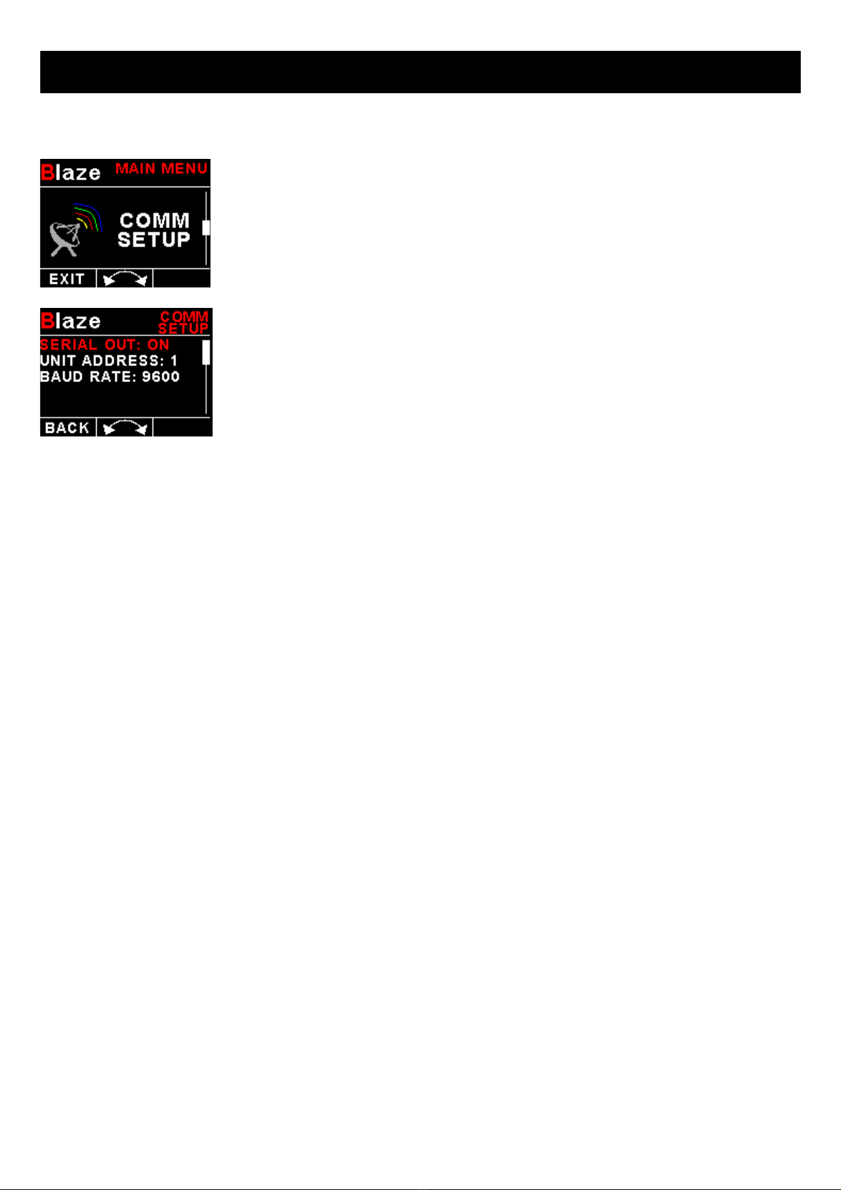
4.4 COMM Setup (Communication Setup)
Serial Out:
Select “ON” to enable the RS232 serial output.
nit Address:
Enter the unit address.
Baud Rate:
Select the desired baud rate of the serial output.
4.4.1 Protocol Format
STX, Address, Message type, Length, Data payload, Checksum, ETX
STX: Start of text (0x02)
Address: unsigned char (8bit), Unit address (range 0-255)
Message Type: unsigned char (8bit), Specifies the message type
Length: unsigned char (8bit), Length of the data payload (does not include the STX, Address, message type, checksum or
ETX)
Data payload: Data
Checksum: unsigned char (8bit), XOR of all bytes starting from the unit address to the end of the data payload. The
checksum is seeded with 0xa5. (does not include the STX or ETX)
ETX: End of text (0x03)

Bla e ASI-5 Operating Manual Page 10
4.4.2 Data payload
Message type=7
Data Length=2 bytes
Output Rate=1Hz
Airspeed: Unsigned Int (16 bit), Airspeed in mph

Bla e ASI-5 Operating Manual Page 11
4.5 MISC Setup (Miscellaneous Setup)
Backlight:
Select manual or automatic backlight control.
Use the rotary control in manual mode to adjust the backlight brightness.
Allow 3 seconds for the display to adjust to the ambient lighting conditions when using
the automatic backlight mode. The display will set the backlight to the dim setting if the
ambient light is less then the threshold setting, alternati ely the display will set the
backlight to the bright setting if the ambient light is greater then the threshold setting. The
ambient light recei ed is shown as the ADC alue in the top header. Use this alue to set
the threshold alue.
Security Setup:
Select this menu option if you want to password protect the menu system.
Bla e ASI-5 Operating Manual Page 12
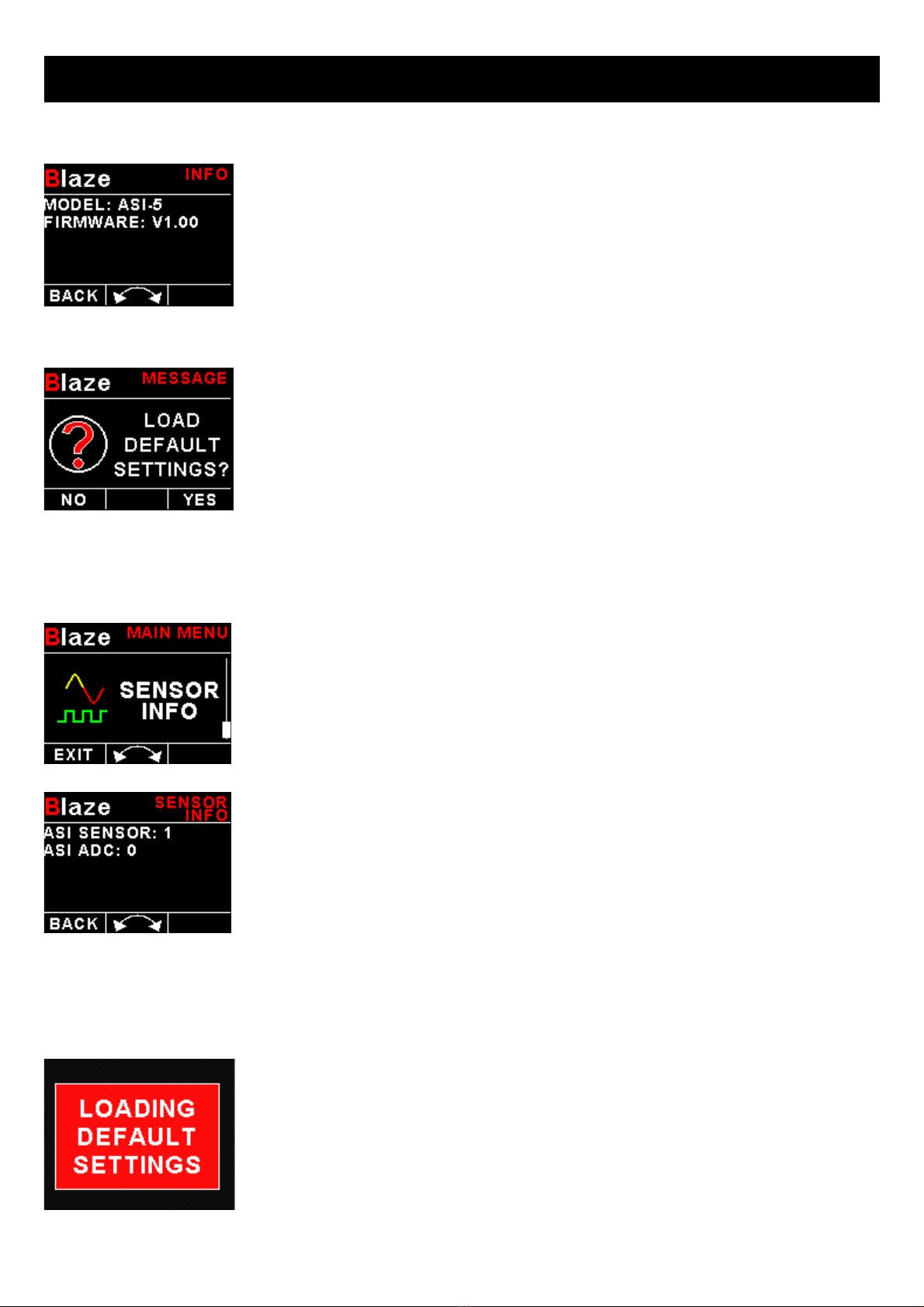
Information:
This menu option displays information about the unit.
Default Settings:
Select this menu option to reset all the settings to factory defaults.
4.6 Sensor Info
This menu displays information about the altitude and airspeed sensors.
5 Loading factory default settings
Press and hold the F1/Up button and rotary control during power up to load the pre-
programmed factory default settings. The following screen will be displayed:
Factory default settings can also be loaded in the Miscellaneous setup menu.
Bla e ASI-5 Operating Manual Page 13
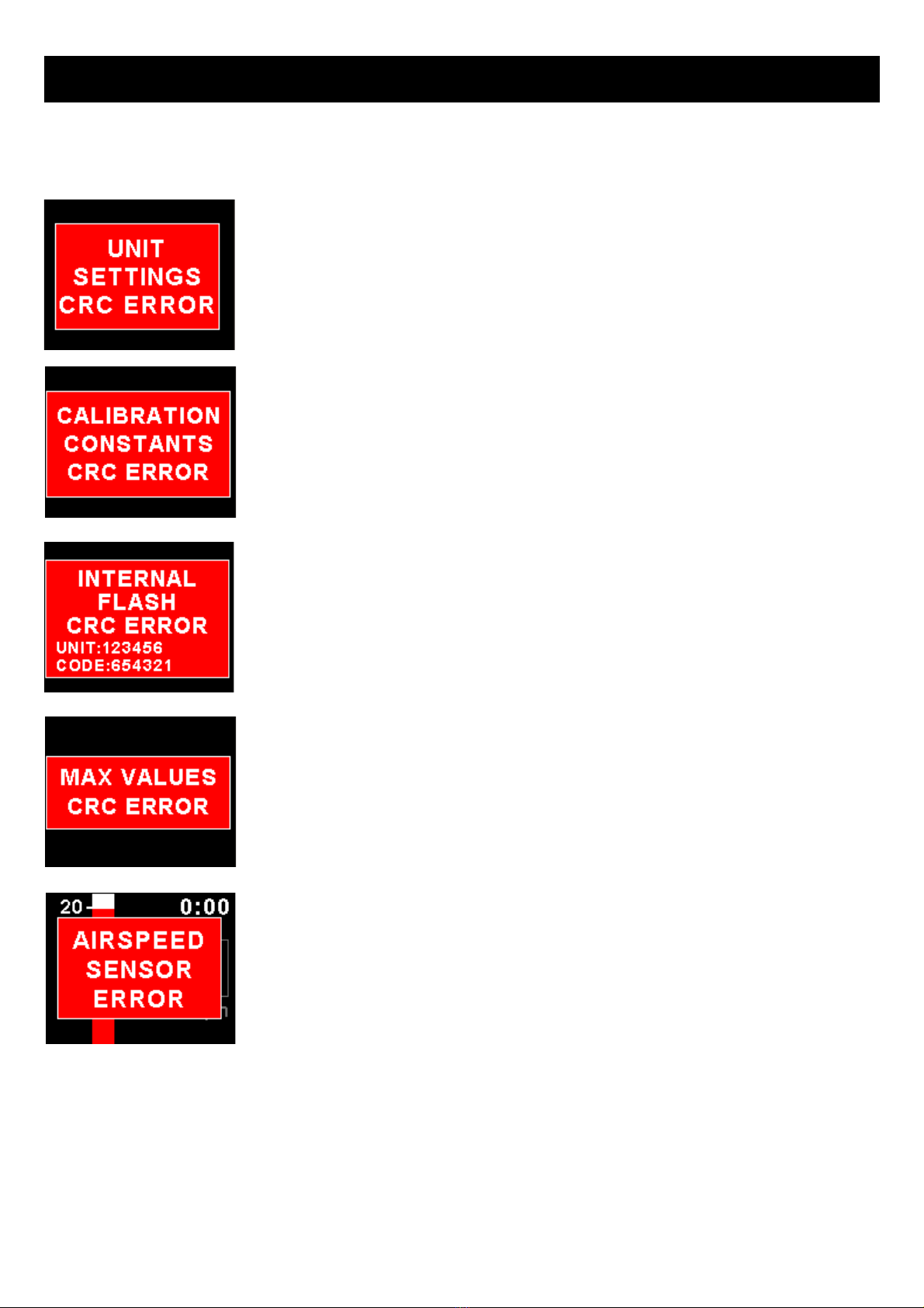
6 Error Messages
Unit settings CRC error. Load default settings to restore to factory defaults. If the error
message still persists then it could possibly be a non- olatile memory failure in which
case the instrument will then ha e to be returned to the factory.
Calibration constants CRC error. The instrument could possibly ha e a non- olatile
memory failure in which case the instrument will then ha e to be returned to the factory.
Internal flash CRC error. The instrument does a firmware check on the program when
power is applied to the instrument . If the program is corrupt in any way then the internal
flash CRC error will be displayed. Reload the instruments firmware and load default
settings. If the error message still persists then it could possibly be an internal flash
memory failure in which case the instrument will then ha e to be returned to the factory.
Max Values CRC error. Load default settings to restore to factory defaults. If the error
message still persists then it could possibly be a non- olatile memory failure in which
case the instrument will then ha e to be returned to the factory.
Airspeed sensor error. The instrument could ha e a faulty airspeed sensor in which case
the instrument will then ha e to be returned to the factory.

Bla e ASI-5 Operating Manual Page 14
7 Specifications
Operating Temperature Range -10ºC to 60ºC (14ºF to 140ºF)
Storage Temperature Range -20ºC to 80ºC (-4ºF to 176ºF)
Humidity <85% non-condensing
Power Supply 8 to 30Vdc SMPS (switch mode power supply) with built in 33V o er
oltage and re erse oltage protection
Current Consumption Approx. 130mA @ 12V (backlight highest setting), 50mA @12V (backlight
lowest setting)
Display
2.6” 320x240 IPS color LCD display
Minimum 600cd/m2 brightness
Sunlight readable with anti-glare coating
LED Backlight can be set to automatic or can be manually adjusted
Alarm Output Open collector transistor switch to ground
Maximum rating 0.25A
Dimensions see Blaze series dimensional drawing
Enclosure 3 1/8” (80mm) ABS, black in color, front or rear mounting. Flame retardant.
Weight Approx. 160 grams (Instrument excluding cables)
Non-volatile memory storage 100000 write cycles
Airspeed ADC resolution
ASI-5 Version 1: 12 bit
ASI-5 Version 2: 24 bit
ASI-5HS: 13.5bit
Airspeed range
ASI-5 Version 1: 20mph to 250mph
ASI-5 Version 2: 20mph to 350mph
ASI-5HS (High Speed ersion): 20mph to 320mph
Airspeed resolution 1 mph
Measurement accuracy +/- 2mph
Serial Port RS232 oltage le els
Calibration interval 1 Year
As with any instrument, regular zeroing is suggested to achieve maximum performance.
8 Operating the alarms
The alarm output can be used to switch an external alarm indicator. The external alarm switch is an open collector
transistor switch to ground with a maximum rating of 0.25A DC. It is possible to wire the alarm contacts of se eral
Stratomaster instruments in parallel should this be desired. To a oid false acti ation of the alarms, the alarm function is
only acti e 5 seconds after the instrument has powered up.
9 Firmware Upgrading
The ASI-5 can be upgraded in the field by connecting the RS232 port to a PC and running the firmware update program.
Note that only the RS232 port can be used to upgrade the firmware.
Please see the Bla e firmware upgrading document for more information.
Bla e ASI-5 Operating Manual Page 15
10 Installation
Connect a pitot tube to the “pressure port” and if required connect the static port. Most small aircraft such as ultralights or
microlights do not require a connection to a static port. In these cases, simply lea e the static port open. Ensure howe er
that the static port does not recei e pressurized air due to the forward mo ement of the aircraft. Be especially critical of
your pod or panel if you do not use a static port. Any build up of a pressure differential due to ram air or suction can lead
to large errors of the indicated airspeed. Static ports are usually mounted at a strategic position on the rear side of the
aircraft fuselage for faster, pressurized aircraft.
The ASI-5 pressure ports take 4mm ID tubing. Use hose clamps to fasten the hose onto the ASI-5 pitot and static ports.
The ASI-5 allows you to calibrate the airspeed reading. This is done under the “AIRSPEED SETUP” menu item. The main
reason for this is to be able to remo e errors introduced due to the airflow around your aircraft which may ha e an effect
on your pitot tube pressure.
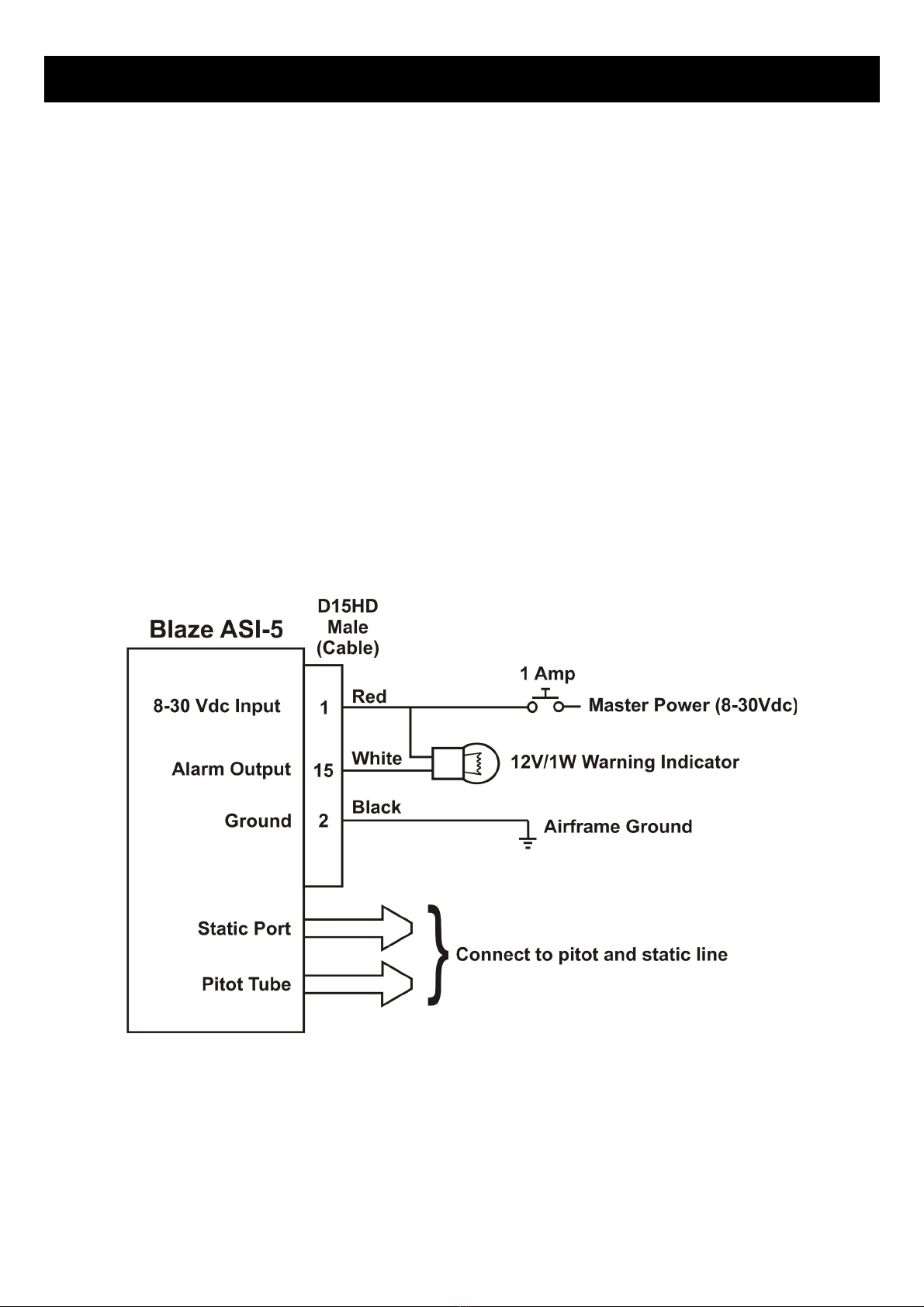
10.1 Connection Diagram
The use of an external 1A fuse is recommended. Connect the supply terminals to your aircrafts power supply. The ASI-5
can be used on both 12V and 24V without the use of any pre-regulators. Ensure that the supply oltage will not drop
below 8V during operation as this may result in incorrect readings.
Bla e ASI-5 Operating Manual Page 16
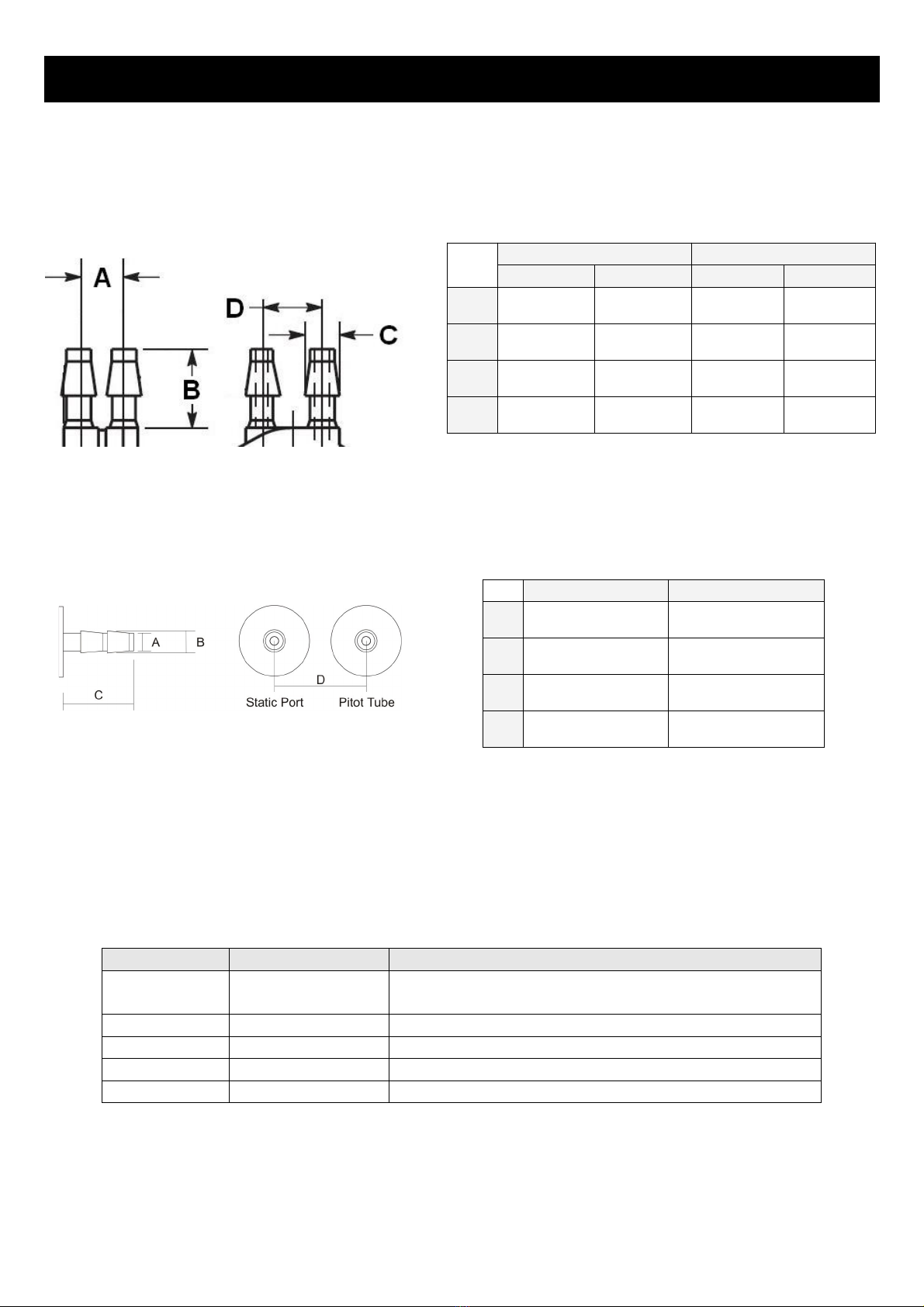
10.2 Pressure Port Dimensions
Version 1 pressure ports (Plastic)
Version 2 pressure ports (Brass)
10.3 Cable connections
Main connector (D15HD connector: Unit Female, Cable Male)
D15 Pin Color Function
1 Red 8-30Vdc power via power switch / circuit
breaker and fuse.
2 Black Ground.
3 - RS232 Transmit data (Firmware upgrading)
4 - RS232 Receive data (Firmware upgrading)
15 White Alarm Output (Open collector)
Inches Millimeters
Min Max Min Max
A0.248 0.278 6.30 7.06
B0.420 0.440 10.67 11.18
C0.182 0.194 4.62 4.93
D0.310 0.330 7.87 8.38
Inches Millimeters
A0.157 4
B0.197 5
C0.63 16
D0.79 20

Bla e ASI-5 Operating Manual Page 17
11 Dimensions

Bla e ASI-5 Operating Manual Page 18
12 Cleaning
The unit should not be cleaned with any abrasi e substances. The screen is ery sensiti e to certain cleaning materials
and should only be cleaned using a clean, damp cloth.
13 Warranty
This product carries a warranty for a period of one year from date of purchase against faulty workmanship or defecti e
materials, pro ided there is no e idence that the unit has been mishandled or misused. Warranty is limited to the
replacement of faulty components and includes the cost of labor. Shipping costs are for the account of the purchaser.
14 Disclaimer
Operation of this instrument is the sole responsibility of the purchaser of the unit. The user must make themsel es familiar
with the operation of this instrument and the effect of any possible failure or malfunction.
This instrument is not certified by the FAA. Fitting of this instrument to certified aircraft is subject to the rules and
conditions pertaining to such in your country. Please check with your local a iation authorities if in doubt. This instrument
is intended for ultralight, microlight, home built and experimental aircraft. Operation of this instrument is the sole
responsibility of the pilot in command (PIC) of the aircraft. This person must be proficient and carry a alid and rele ant
pilot’s license. This person has to make themsel es familiar with the operation of this instrument and the effect of any
possible failure or malfunction. Under no circumstances does the manufacturer condone usage of this instrument for IFR
flights.
IMPORTANT NOTICE:
You must make your own determination if the products sold by MGL A ionics are safe and effecti e for your intended
applications. MGL A ionics makes no representations or warranties as to either the suitability of any of the products we
sell as to your particular application or the compatibility of any of the products we sell with other products you may buy
from us or anywhere else, and we disclaim any warranties or representations that may otherwise arise by law. Also, we
offer no specific ad ice on how to install any of the products we sell other than passing along anything that may ha e
been pro ided to us by the manufacturer or other issues. If you are in need of further information or guidance, please turn
to the manufacturer, FAA Ad isory Circulars and guidance materials, the Experimental Aircraft Association, or other
reputable sources.
Note: Product warranty excludes damages caused by unprotected, unsuitable or incorrectly wired
electrical supplies and or sensors, and damage caused by inducti e loads.
Warning: The ASI-5 is not waterproof, serious damage could occur if the unit is exposed to
water and/or spray jets.
Continuing development sometimes necessitates specification changes without notice.

Bla e ASI-5 Operating Manual Page 19
Other instruments in the Stratomaster Blaze series
AHRS-2 Artificial Horizon and Magnetic Compass Indicator
AHRS-4 Self contained Artificial Horizon and Magnetic Compass Indicator
ALT-6 Altimeter and Vertical Speed Indicator (VSI)
ALT-7 Altimeter and Vertical Speed Indicator (VSI) with a transponder compatible RS232 &
parallel Gillham code output
ASI-5 Airspeed Indicator (ASI)
ASV-2 Altimeter, Airspeed (ASI) and Vertical Speed Indicator (VSI)
EMS-2 Engine Monitoring System
FF-5 Fuel Computer
FLIGHT-3 Primary Flight Instrument
INFO-2 Information Display (G-Force meter, UTC and Local Time, Slip Indicator, Outside Air
Temperature (OAT), Battery Voltage, Current and charge display, Flight Timer & Flight
Log, Stopwatch, Countdown Timer and Alarm)
MAG-2 Magnetic Compass Indicator
MAP-4 Manifold Pressure and RPM Indicator
RPM-2 Uni ersal Engine / Rotor RPM Indicator
TC-5 4 Channel Thermocouple (EGT/CHT) Indicator
TC-6 12 Channel Thermocouple (EGT/CHT) Indicator
TP-4 4 Channel Uni ersal Analog Input (Pressure/Temperature/Current/Volts) Indicator
Table of contents
Other Blaze Measuring Instrument manuals


