Flymaster Vario SD User manual

User manual
Document version:2.0
All manuals and user guides at all-guides.com
all-guides.com

Contents
Page
1 Getting Started 3
1.1 Charging the Battery .................................. 3
1.2 VARIO SD Keys .................................... 3
1.3 Using keys Inside Menu ................................ 4
1.4 Switching VARIO SD On and O ........................... 4
1.5 Resetting the VARIO SD ............................... 5
1.6 Setting the Volume ................................... 5
1.7 Flight Start and Recording .............................. 5
2 Flight Mode 6
3 VARIO SD Elements 7
3.1 Graphical Elements ................................... 7
3.1.1 Battery ..................................... 7
3.1.2 Sound ...................................... 7
3.1.3 Vario ...................................... 8
3.1.4 Altitude graph ................................. 9
3.1.5 Compass .................................... 10
3.2 Data eld Elements ................................... 11
4 Menu mode 13
4.1 Flight Log ........................................ 13
4.2 Set Altimeter ...................................... 15
4.3 Time ........................................... 16
4.4 Vario Acoustics ..................................... 16
4.4.1 Climb Threshold ................................ 16
4.4.2 Sink Threshold ................................. 17
4.4.3 Sink Alarm ................................... 17
4.4.4 Base Frequency ................................. 17
4.4.5 Increments ................................... 17
4.4.6 Volume ..................................... 17
4.5 Advanced Features ................................... 17
4.5.1 Damper ..................................... 18
4.5.2 Cadence ..................................... 18
4.5.3 Dynamic Frequency .............................. 18
4.5.4 Buzzer ...................................... 18
4.5.5 Auto Silent ................................... 19
4.5.6 Vario Integrator ................................ 19
1
All manuals and user guides at all-guides.com

4.6 Screen .......................................... 19
4.7 Language/Units ..................................... 20
4.8 Device Settings ..................................... 20
4.9 RF Probes ........................................ 21
4.10 Probe Alerts ...................................... 22
4.11 Calibration ....................................... 22
5 McCready Functions 24
6 Compass Calibration 25
6.1 Accelerometer Calibration ............................... 25
6.2 Magnetometer Calibration ............................... 25
7 Firmware 28
2
All manuals and user guides at all-guides.com

1 Getting Started
Fully charge battery before using your Flymaster for the rst time.
Figure 1.1: right view
The battery may be charged by either connecting the VARIO SD USB connector to the wall socket charger,
or to a powered USB port using the USB cable. USB connector can be found on the right side of the
VARIO SD (see gure 1.1).
1.1 Charging the Battery
Flymaster VARIO SD has an advanced battery power management system, which gives the pilot accurate
information about the battery state, as well as the charging time and battery remaining time.
To charge the Flymaster VARIO SD battery you may use the wall charger, the USB cable, or the car
charger. Original Flymaster accessories are recommended in order to avoid damage to the power manage-
ment system.
The Flymaster VARIO SD has 2 charging modes, namely,
Quick Charge
and
Slow charge
. The charging
mode choice is automatic and based on the power source.
Quick charge
mode is activated when charging
with the wall charger or the car charger, while Slow Charge mode is activated when a USB cable connected
to a PC or MAC is used.
Charging, and battery status information is shown on both the power up screen and the
Shutdown
menu.
When the Flymaster VARIO SD is connected to a power supply (wall charger or via USB cable), even
with the unit o, the instrument will show if it is being
Slow
or
Fast
charged. The time remaining to
full charge is also shown. This may not appear immediately when a power source is connected, since the
instrument requires some time to calculate the remaining charge time. A
Slow
charge is ok for topping
up the battery but not for fully charging. Use the wall or car charger to fully charge the instrument.
Note: The instrument will not charge when it is turned on and connected to a PC. The
instrument must be turned o in order to charge the battery using the PC USB port . This
behavior is deliberate to prevent overwhelming competition organizer's download hubs.
Note: Charging the instrument with high ambient temperatures should be avoided. Such
action can cause the battery to overheat and aect battery health.
1.2 VARIO SD Keys
Four keys are used to interact with VARIO SD (see Figure 1.2). In this manual we will call MENU key
- S1, ENTER key - S2, UP key - S3, and DOWN - S4. Each key has 2 functions depending whether the
device is in ight mode or in menu mode. Additionally the MENU key is used to
power-up
the VARIO
SD when it is switched o.
3
All manuals and user guides at all-guides.com

Figure 1.2: VARIO SD keypad
Note: If the active page includes a Map (Task Map, or Airspaces Map) FS Keys denition will
be ignored. In this case S3, and S4, will zoom in and out of the map whilst the S2 will switch
page.
In menu mode all keys have xed functions shown by symbols on the keys namely S3=Move Up S4=Move
Down, S2=Enter and S1=Back(Exit).
1.3 Using keys Inside Menu
Changing parameters on the VARIO SD can be performed through the menu. Changing a parameter
involves accessing the menu, selecting an option, and then changing a specic eld value. Accessing the
main menu can be done by pressing the MENU key in ight mode. Once in the menu, UP(S3), and
DOWN(S4) keys can be used to scroll up and down through the menu options list. During the scrolling
process the selected option is highlighted. The ENTER(S2) key should be used to access the option.
Depending on the menu option, a new menu options list, or a data elds list appears. In any time pressing
the MENU(S1) key takes you back. When accessing data elds the associated menu option becomes
grayed
and the respective eld data item is highlighted. Using the UP and DOWN keys changes the value on
each eld. Pushing the ENTER key moves to the next eld, or in same cases to the next character/digit.
Conversely, pushing MENU key moves to the previous eld, or to the previews character/digit. If the
ENTER key is pushed on the last eld all the data in the selection section is stored and control returns to
the conguration menu. Inversely, if the MENU key is pushed on the rst data eld the changed settings
are ignored and control is returned to the conguration menu.
Tip: When setting a data eld that involves setting several characters, e.g. when dening
a waypoint name, after dening the desired characters, pushing the ENTER key continually
for more than 2 seconds will make the cursor jump to the next data eld, or return to the
conguration menu if no more data eld needs to be set.
1.4 Switching VARIO SD On and O
To switch on the VARIO SD , briey push the S1 key (Menu Key). This will display the start up screen
with a 10 second countdown . Pushing the S2 (Enter key) before the 10 seconds have elapsed will power
up the VARIO SD . The VARIO SD initiates in ight mode. If the S2 key is not pushed within 10 seconds
the VARIO SD returns to sleep. To switch o the VARIO SD , push the S1(menu key) to activate menu
mode, then use the S3 or S4 to select the
Shutdown
item, and nally push the S2 Key.
4
All manuals and user guides at all-guides.com

1.5 Resetting the VARIO SD
The reset procedure allows the pilot to restart the VARIO SD in the unlikely event that it freezes, or stops
responding (if this ever occur please report it to our support email). To reset the VARIO SD push S1
(Menu) key and the S4 (Down arrow) key, simultaneously, for at least two seconds. The display will go
blank and after will return in Flight mode.
1.6 Setting the Volume
The VARIO SD sound volume can be adjust using one FS Key, or trough the
Vario Accoustics
option of
the
Settings
Menu (see Section 4.4). The VARIO SD has six dierent sound levels, plus
no sound
. The
current volume level can be seen using the sound element (see Section 3.1.2 for more details).
Pressing the dened FS Key will scroll up the sound level until the maximum value. Pressing more will
mute the sound before start scrolling again starting from the minimum value.
Note: Changing the volume using an FS key is only valid for the current ight, and will not
override the volume level setting. Every time the instrument is turned on, if the sound is
muted, an alarm is generated in order to notify the pilot.
1.7 Flight Start and Recording
Most of the VARIO SD features are only available after the
Flight Start
. This procedure is taken in
order to avoid wrong calculations due to missing data. Flight starts when average vario is greater than
+-0.15m/s
5
All manuals and user guides at all-guides.com
all-guides.com

2 Flight Mode
The Flymaster VARIO SD has two main working modes, namely Flight mode, and Menu mode. Flight
mode is used during ight, and this allows the user to see information such as Altitude, Speed, or Vario.
The VARIO SD can have up to 16 dierent pages (see Figure 2.1) in memory. Each page corresponds to
a dierent screen, which can be completely congured by the user. A set of 16 pages is called a Layout.
Figure 2.1: Page examples (Some elements on the picture could not be available on your model)
Screen layout can be congured by the user using a free application, called
Flymaster Designer
which can
be downloaded from the Flymaster website (www.ymaster.net). This intuitive tool allows the user to
create an unlimited number of layouts, which can be saved to the computer, uploaded to the instrument,
and even shared with other Flymaster users. See the Designer user manual, available on the website for
more information about the Designer tool.
Designing a Layout consists of inserting a set of objects, called
Elements
, in the desired position, and with
the desired dimensions, in each of the available 16 pages. The Designer works by
what you see is what
you get
. This means that when you insert a element in a page, and after uploading the layout to the
instrument, you will see exactly the same thing on the VARIO SD screen.
Note: If a Layout is uploaded to the VARIO SD the previews layout is deleted (all pages are
deleted).
There are several elements available for the VARIO SD which are presented in the following section.
6
All manuals and user guides at all-guides.com

3 VARIO SD Elements
The main objective of an element is to provide information to the user. Elements can be Graphical, or
Data Field type. Each element has its own properties which can be changed in order to alter the element
behaviour, and/or shape.
3.1 Graphical Elements
Graphical elements are characterized by providing information in a graphical way. Most of the graphical
elements have xed dimensions, although their position can be altered.
As the VARIO SD rmware evolves the list of Graphical Elements will likely grow. The current list
includes the following graphical elements.
3.1.1 Battery
The Battery Element provides a graphical indication of the current battery level. In Table 3.1 it is possible
to see the relationship between what is shown and the actual battery level in percentage. This element
has xed dimensions.
Table 3.1: Battery Element description
Symbol Description
Battery level above 90%
Battery level between 70% and 89%
Battery level between 50% and 69%
Battery level between 30% and 49%
Battery level between 15% and 29%
Less than 15% battery remaining
3.1.2 Sound
The Sound Element provides graphical representation on the current volume level. Table 3.2 Shows the
relationship between what is shown and the sound level. This element has xed dimensions.
Table 3.2: Sound Element description
Symbol Description
Sound Level 6 (maximum sound level)
Sound Level 5
Sound Level 4
Sound Level 3
Sound Level 2
Sound Level 1
Sound is muted (No sound)
7
All manuals and user guides at all-guides.com

3.1.3 Vario
The Analog Vario Elements shows information regarding the analogue instantaneous vertical speed. There
are four dierent Elements that can be used to display the vario. All of these element can be resized and
re-positioned.
Analog Vario
This Element which can be resized and repositioned, graphically represents the rate of climb, scaled from
0 m/s to +/-10 m/s depending if you are climbing or sinking Figure 3.1.
Figure 3.1: Analog Vario
When the VARIO SD detects that the pilot is climbing, a black bar starts to grow on the left, from the
bottom of the scale to the top ,with 0.1 m/s increments. The same bar grows on the right, from the top
of the scale to the bottom, if sinking is detected.
Big Analog Vario
The
Big Analog Vario
element shows the instantaneous vertical speed (Figure 3.2). This element can be
resized and re-positioned.
Figure 3.2: Big Analog Vario
This Element graphically represents the rate of climb, scaled from 0 m/s to +/-10 m/s depending if you
are climbing or sinking. In this Element a black bar starts from the middle of the scale and grows at 0.1
m/s increments, up to 5 m/s at the top of the scale. When 5 m/s value is reached the black bar starts to
disappear from 0 m/s (middle of the scale) until the top of the scale. When the bar completely disappears
the climbing rate is equal, or above 10 m/s. The same process occurs when descending, but from the
middle of the scale to the bottom.
Double Bar Analog Vario and McCready Indicator
The Double Bar Analog Vario element shows not only the instantaneous vertical speed, but also the
Average Thermal
and
Next Expected Thermal
(McCready Indicator) (see Figure 3.3). This element can
be resized and re-positioned. The element consists of 4 columns. In the left most column a black bar is
8
All manuals and user guides at all-guides.com
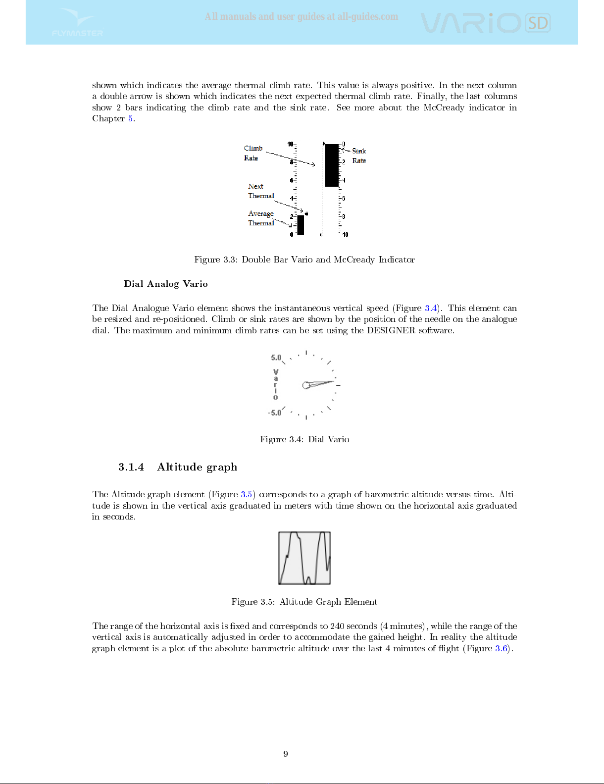
shown which indicates the average thermal climb rate. This value is always positive. In the next column
a double arrow is shown which indicates the next expected thermal climb rate. Finally, the last columns
show 2 bars indicating the climb rate and the sink rate. See more about the McCready indicator in
Chapter 5.
Figure 3.3: Double Bar Vario and McCready Indicator
Dial Analog Vario
The Dial Analogue Vario element shows the instantaneous vertical speed (Figure 3.4). This element can
be resized and re-positioned. Climb or sink rates are shown by the position of the needle on the analogue
dial. The maximum and minimum climb rates can be set using the DESIGNER software.
Figure 3.4: Dial Vario
3.1.4 Altitude graph
The Altitude graph element (Figure 3.5) corresponds to a graph of barometric altitude versus time. Alti-
tude is shown in the vertical axis graduated in meters with time shown on the horizontal axis graduated
in seconds.
Figure 3.5: Altitude Graph Element
The range of the horizontal axis is xed and corresponds to 240 seconds (4 minutes), while the range of the
vertical axis is automatically adjusted in order to accommodate the gained height. In reality the altitude
graph element is a plot of the absolute barometric altitude over the last 4 minutes of ight (Figure 3.6).
9
All manuals and user guides at all-guides.com

Figure 3.6: Altitude Plot
Figure 3.7: Compass Element
3.1.5 Compass
The Compass element (Figure 3.7) show all the data provided by the VARIO SD built in magnetic compass.
This element can be resized and moved around the screen. The compass includes an arrow which is always
alined with the VARIO SD . If the VARIO SD is turned the cardinal points will also turn in order the
arrow tip points the right cardinal point.
Figure 3.8: Compass example
In the example of Figure 3.8 the VARIO SD is pointing almost to East. The direction is represented by
the arrow, and also indicated numerical (76
°
degrees).
10
All manuals and user guides at all-guides.com
all-guides.com

3.2 Data eld Elements
Data eld elements can be used to shown numerical information like altitude, vertical speedand many
others.
These elements have congurable size, and position, although the text within has only 3 possible sizes.
The folowing table explains the available data elds. As the VARIO SD rmware evolves this list will
likely grow.
Table 3.3: Data elds Description
Field ID Description
Date Current date. This value is automatic set when the device gets a
valid GPS Signal
Altitude Current altitude. This altitude is calculated based on the baro-
metric pressure and depends on the QNH value.
Time Current local Time. This value is automatic revised when the
device gets a valid Gps Signal. (see Note 2)
Dur. Flight Duration. Duration of the current ight.
Battery Shows battery strength as a percentage of complete charge
Alt.Gain Altitude Gain. Altitude gained in current thermal.
Max.Alti Maximum altitude reached during current ight. This is based on
barometric altitude.
Vario Instant vario value.
Ave.Vario Average Vario calculated using an integration time constant in
order to indicate smoother climbing rates.
Max.Climb Once a ight has started, it shows the maximum rate of climb
encountered during the ight. This value uses the integrated vario
not the instantaneous rate of climb. This provides good indication
of the quality of the day's thermals. This value is reset when the
instrument is switched o.
Max.Sink Once a ight has started shows the maximum sink encountered
during the ight. Note that these values are using the integrated
vario. When the instrument is switched o this value is reset back
to zero.
Altitude2 Second Altimeter which can be set independently to the main
altimeter.
Altitude3 Third Altimeter which can be set independently to the main al-
timeter. Altimeter3 can be quickly reset to 0 using a short cut
key which can be user congured.
Abs.Pressure Absolute atmospheric pressure value in Pascals.
Flight Level Current altitude in hundreds of feet, based on a xed QNH of
1013.25hPa.
Above To Altitude above takeo is the altitude over the ight starting point.
MotorTemp Motor Temperature (available when connected with Flymaster
M1).
RPM Motor revolutions per minute (available when connected with Fly-
master M1).
Fuel Fuel level in liters (available when connected with Flymaster M1).
Page Num. Current layout active page number.
Voltage Current battery level in Volts.
Int.Temperature Temperature inside the instrument.
Pulse Current heartbeat in beats per minute, when using the Flymaster
Heart-G sensor.
Steps/Min Cadence showing number of steps per minute.
Steps Number of steps taken since counting initiated.
Continued on next page
11
All manuals and user guides at all-guides.com
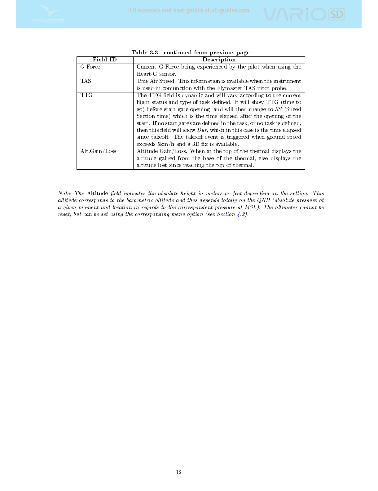
Table 3.3 continued from previous page
Field ID Description
G-Force Current G-Force being experienced by the pilot when using the
Heart-G sensor.
TAS True Air Speed. This information is available when the instrument
is used in conjunction with the Flymaster TAS pitot probe.
TTG The TTG eld is dynamic and will vary according to the current
ight status and type of task dened. It will show TTG (time to
go) before start gate opening, and will then change to
SS
(Speed
Section time) which is the time elapsed after the opening of the
start. If no start gates are dened in the task, or no task is dened,
then this eld will show
Dur
, which in this case is the time elapsed
since takeo. The takeo event is triggered when ground speed
exceeds 5km/h and a 3D x is available.
Alt.Gain/Loss Altitude Gain/Loss. When at the top of the thermal displays the
altitude gained from the base of the thermal, else displays the
altitude lost since reaching the top of thermal.
Note- The
Altitude
eld indicates the absolute height in meters or feet depending on the setting. This
altitude corresponds to the barometric altitude and thus depends totally on the QNH (absolute pressure at
a given moment and location in regards to the correspondent pressure at MSL). The altimeter cannot be
reset, but can be set using the corresponding menu option (see Section 4.2).
12
All manuals and user guides at all-guides.com
4 Menu mode
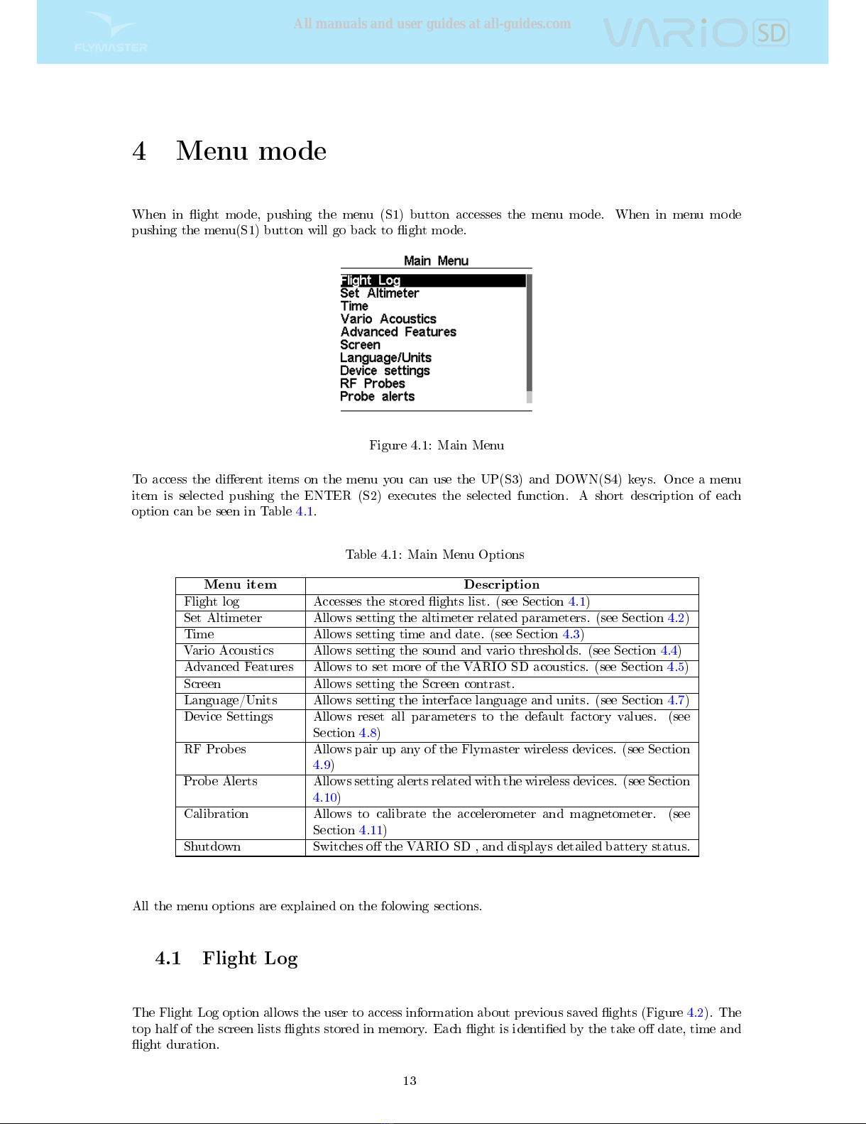
When in ight mode, pushing the menu (S1) button accesses the menu mode. When in menu mode
pushing the menu(S1) button will go back to ight mode.
Figure 4.1: Main Menu
To access the dierent items on the menu you can use the UP(S3) and DOWN(S4) keys. Once a menu
item is selected pushing the ENTER (S2) executes the selected function. A short description of each
option can be seen in Table 4.1.
Table 4.1: Main Menu Options
Menu item Description
Flight log Accesses the stored ights list. (see Section 4.1)
Set Altimeter Allows setting the altimeter related parameters. (see Section 4.2)
Time Allows setting time and date. (see Section 4.3)
Vario Acoustics Allows setting the sound and vario thresholds. (see Section 4.4)
Advanced Features Allows to set more of the VARIO SD acoustics. (see Section 4.5)
Screen Allows setting the Screen contrast.
Language/Units Allows setting the interface language and units. (see Section 4.7)
Device Settings Allows reset all parameters to the default factory values. (see
Section 4.8)
RF Probes Allows pair up any of the Flymaster wireless devices. (see Section
4.9)
Probe Alerts Allows setting alerts related with the wireless devices. (see Section
4.10)
Calibration Allows to calibrate the accelerometer and magnetometer. (see
Section 4.11)
Shutdown Switches o the VARIO SD , and displays detailed battery status.
All the menu options are explained on the folowing sections.
4.1 Flight Log
The Flight Log option allows the user to access information about previous saved ights (Figure 4.2). The
top half of the screen lists ights stored in memory. Each ight is identied by the take o date, time and
ight duration.
13
All manuals and user guides at all-guides.com

Figure 4.2: Flight log
Flights can be selected using UP and DOWN keys. For the selected ight additional information is
displayed on the bottom half of the screen:
Max. Altitude - Maximum altitude during ight (ASL).
T.o Alti. - Take o altitude.
Above To- Altitude above take o
Max. Sink - Maximum sinking rate during ight
Max Climb - Maximum climbing rate during ight
Distance - Distance own
Pushing the ENTER key will display the Flight Log Action List, with options:
Delete ight
Delete all ights
Each of the options is explained in the following sections.
Also if you use a ight data download application and request the ight list while the Flight
Log Action is active only selected ight will be reported to the downloader application.
Delete Flight
Selecting the
Delete Flight
option will delete the selected ight from memory. Before deleting the ight,
a message is displayed asking the user to conrm the action (Figure 4.3).
14
All manuals and user guides at all-guides.com

Figure 4.3: Delete Flight
Delete All Flights
All of the ights in the VARIO SD can be deleted by selecting the
Delete all ights
option. A message is
displayed asking the user to conrm the action of deleting all ights (Figure 4.4).
Figure 4.4: Delete all ights
WARNING:
Deleting all ights will completely erase the ight log memory, all track logs
will permanently erased.
4.2 Set Altimeter
The
Set Altimeter
page (Figure 4.5) allows the user to adjusts the barometric altimeter. A barometric
altimeter calculates altitude based on atmospheric pressure . Since atmospheric pressure can vary sub-
stantially with meteorological conditions, and so with time, the barometric altitude also varies according.
In order to have the correct altitude for a certain place the altimeter should be calibrated.
Calibrating the altimeter can be achieved by entering the know altitude of the location. Entering an
altitude automatically calculates the QNH, which is the local barometric pressure adjusted to sea level.
Alternatively, the altimeter can be calibrated by adjusting the QNH for the local, and time. Changing the
QNH will adjust the barometric altitude.
15
All manuals and user guides at all-guides.com
all-guides.com

Figure 4.5: Set Altimeter
4.3 Time
The
Time
page allows the user to set the time, and date. (Figure 4.6) Time and date values are important
because they are used to classify data in the Flight Log.
Figure 4.6: Timing Parameters
4.4 Vario Acoustics
The
Vario Acoustics
settings menu option allows the user to change vario sound related parameters. The
user can change the climbing, and sinking rate sound through the respective threshold values. These
thresholds correspond to the climbing and sinking rates at which the sound activates. The user can also
dene in the Acoustic Thresholds option the sink alarm and the sound volume of is the VARIO SD (Figure
4.7).
Figure 4.7: Vario Acoustics
4.4.1 Climb Threshold
The
Climb Threshold
denes the rate of climb at which the vario will start beeping. The frequency of the
rst beep is dened trough the Base Frequency parameter,and steadily increases according the Increments
parameter value.
The default value for
Climb Threshold
is 0.1m/s. This means that beeping starts once the instantaneous
vario value goes above 0.1m/s.
16
All manuals and user guides at all-guides.com

4.4.2 Sink Threshold
The
Sink Threshold
is the rate of descent at which the vario will emit a low frequency sound. Contrary
to the climb sound the sink sound is continuous. The deeper the sink rate the lower the sound frequency.
Default value for this parameter is -2 m/s, we suggest setting a value lower than the natural sink rate of
the glider when ying with speed bar in still air.
4.4.3 Sink Alarm
The
Sink Alarm
denes a vertical speed value at which a sound (alarm siren) starts to be produced. For
example, if the
Sink Alarm
is set to -10m/s, then if the instantaneous vario goes below -10m/s, and alarm
will be red. This alarm can be used to identify high vertical speeds, as for example, in a spiral dive. The
Sink Alarm parameter can vary from 0 to -25m/s. Set the Sink Alarm to
O
to disable the alarm.
4.4.4 Base Frequency
The audio frequencies can be adjusted to match the user's preference, by setting the
Base Frq
and
Incre-
ments
.
The
Base Frq
is the rst frequency used to produce the initial sound which corresponds to the climb
threshold (by default 0.1 m/s). Later, as the climb rate increases, a bip, bip sound is produced for which
the cadence, and frequency, also increase. The
Base Frq
can be set from 500 to 1500 Hz. The higher is
the frequency value, the higher pitched the sound is.
In order to change the base frequency value press the ENTER key after the
Audio Frequencies
menu
option is highlighted. This action will highlight the
Base Frq
value so it can be increased using the UP
key, or decreased using the DOWN key. The ENTER key should then be pressed, thus conrming the
Base Frq
setting. The preset value for
Base Frq
is 700 Hz.
4.4.5 Increments
The
Increments
parameter sets the frequency increment for each 0.1 m/s climb rate increase. The
incre-
ments
can be set from 1 to 99 Hz. The preset value for
Increments
is 10 Hz.
Considering an
Increments
value of 10, and
Base Frq
of 700 Hz, the vario frequency at 1 m/s is 800 Hz.
4.4.6 Volume
The nal option allows the user to adjust the sound volume. The VARIO SD has six dierent sound levels,
plus
no sound
. Pressing UP, or DOWN, keys will respective increase, or decrease the sound level. After
setting the sound value , to conrm and return to the Settings menu press the ENTER key. The new
sound level is saved in memory and is used when the VARIO SD is turned on. Sound volume can also be
adjusted using one FS key. However, the sound level adjusted using the FS key is not kept in memory, so
is only valid until the VARIO SD is turned o.
In
Flight Mode
the current volume level can be seen using the sound element (see Section 3.1.2 for more
details).
4.5 Advanced Features
The advanced features settings option can be used to set more of the VARIO SD vario acoustics. (Figure
4.8).
17
All manuals and user guides at all-guides.com

Figure 4.8: Advanced Features
4.5.1 Damper
The VARIO SD 's vertical speed calculation is based on air pressure variations. It is very seldom to have
air pressure absolutely stable. Turbulence caused by air moving near the sensor is sucient to cause
small variations in pressure. For this reason the VARIO SD lters (averages) the pressure data to prevent
constantly detecting tiny pressure variations. The value that denes how must the pressure is ltered is
the
Damper
. Setting a lower damper value caused the VARIO SD to become more responsive but harsher.
Inversely a higher value causes the VARIO SD to be less responsive but smoother. The default value is 6.
4.5.2 Cadence
When a rate of climb is higher than that specied by the Climb threshold the VARIO SD creates a
beeping sound. The rate (cadence) of the beeps increases as the climb rate increases. This increase in rate
is not linear. The cadence parameter species which cadence curve should be used. Current there are 2
possibilities represented in the graph of Figure 4.9.
Figure 4.9: Cadence timing
4.5.3 Dynamic Frequency
The VARIO SD beeps at a specied pitch (frequency) when a certain rate of climb is encountered. When
dynamic frequency is o, the pitch (frequency) of that beep will remain constant if the rate of climb
changes. With dynamic frequency on, the pitch of the beep may vary if the rate of climb varies during
the individual beep.
4.5.4 Buzzer
Is so called because of the sound it emits, which resembles a buzzing sound.
The buzzer sound is produced when the rate of climb is close to, but has not yet reached the specied
Climb threshold (see 13.3.1). This value is set between 0 and 9 with each unit corresponding to be 0.1 m/s,
ie. 3 is 0.3m/s. Subtracting this decimal value from the climb threshold will give us the value at which the
18
All manuals and user guides at all-guides.com

VARIO SD will start buzzing. For example with the VARIO SD default values, Climb threshold=0.1m/s,
and Buzzer=3 (0.3m/s) the buzzing with start at -0.2m/s because 0.1 - 0.3= -0.2. In this case at 0.1m/s
directly below the Climb threshold the VARIO SD will emit a constant sound varying rapidly in pitch
from around 100hz to the set base frequency at which the rst beep is emitted. This is the buzzer sound
and may resemble a growl noise. Setting the Buzzer value to
O
will disable the buzzer feature.
Although the Buzzer will sound very annoying on the ground it becomes an amazing companion in ight
allowing the pilot to pick-up thermals he would have usually missed.
Figure 4.10: Buzzer
A practical example of the advantages of the buzzer feature can be illustrated in Figure 4.10 In this
example both pilots are sinking at -1.0 m/s. The orange paraglider has a VARIO SD for which the
climbing threshold is set to 0.1 m/s and the Buzzer parameter is set to 3 (0.3 m/s). The green paraglider
has a typical vario for which the climbing threshold is set to 0.1 m/s.
As shown in the gure, when both pilots enter the thermal nothing is heard. The air is rising at 0.1 m/s
but both pilots are descending at -0.9 m/s. In the second zone of the thermal the air is rising at 0.8 m/s,
and so pilots are descending at -0.2 m/s. At this stage the orange pilot starts to hear the Buzzer brrrrr
sound of his VARIO SD , which helps him to center the thermal, while the green pilot is still unaware of
the thermal. Finally, in the 3 zone, the air is rising at 1.2 m/s, and so both pilots climb at 0.2 m/s. The
VARIO SD pilot starts to hear his vario beep... beep... sound, and it is only at this point the green pilot
hears the rst beep from his instrument.
4.5.5 Auto Silent
Setting
Auto silent
option
ON
will keep the VARIO SD 's buzzer quiet until a
Start Flight
has been
detected. (see Section 1.7) This function avoids listening the vario sound while waiting to take o. The
audio will then be kept active until the VARIO SD is switched o. The default value for the auto silent
parameter is
ON
.
4.5.6 Vario Integrator
The Integrated vario is calculated by integrating the vertical speed during a period of X seconds dened
by this value.
4.6 Screen
The screen menu option allows the user to set the Screen contrast
(Figure 4.11).
19
All manuals and user guides at all-guides.com
Other manuals for Vario SD
1
Other Flymaster Measuring Instrument manuals


