Blickfeld Cube 1 User manual
Cube
Cube Range

2 Cube , Cube Range Version 2.1
DETAILS
Blickfeld GmbH
Barthstr. 12
80339 Munich
Germany
Tel.: +49 89 2306935 00
E-mail: info@blickfeld.com
Website: www.blickfeld.com
©2021
DOCUMENT HISTORY
Version Date Revised Contents
1.0 June 1, 2020 Initial creation
1.1 November 24, 2020 Commissioning
2.0 April 27, 2021 Cube Range added
2.1 May 19, 2021 Added coordinate system
description and LiDAR
output

Version 2.1 Cube , Cube Range 3
Contents
1 About this document ...............................5
1.1 General information ............................................ 5
1.2 Symbols and signal words ...................................... 5
1.3 Abbreviations................................................... 6
2 Safety notes .......................................7
2.1 Intended use ................................................... 7
2.2 Unintended use ................................................ 7
2.3 Device-specific safety instructions .............................. 8
2.3.1 Laser safety ............................................................8
2.3.2 Electrical safety ........................................................9
3 Product overview ................................. 10
3.1 Description .....................................................10
3.1.1 Dimensions and structure ............................................10
3.1.2 Materials.............................................................. 11
3.1.3 Function description.................................................. 11
3.2 Electronic properties............................................12
3.2.1 Supply voltage ........................................................12
3.2.2 Power supply .........................................................12
3.2.3 Power consumption ..................................................12
3.2.4 Data transmission ....................................................12
3.2.5 Thermal properties ...................................................12
3.3 Properties ......................................................13
3.3.1 Laser source ..........................................................13
3.3.2 Field-of-view..........................................................13
3.3.3 Scan pattern ..........................................................14
3.3.4 Point cloud output ...................................................15
3.3.5 Coordinate system ...................................................16
3.3.6 Technical specifications ...............................................17
4 Installation .......................................20
4.1 Scope of supply................................................20
4.2 Mounting......................................................20
4.3 Electrical installation/cabling .................................. 23
5 Commissioning ...................................24
5.1 Initial connection ..............................................24
5.2 Troubleshooting of the WebGUI connection....................26
5.3 Software tools .................................................26
5.4 Cube reset .....................................................27

4 Cube , Cube Range Version 2.1
6 Maintenance .....................................28
6.1 Cleaning.......................................................28
6.2 Repair work....................................................28
7 Putting out of operation ...........................29
7.1 Storage ........................................................29
7.2 Disposal .......................................................29
8 Customer service/support .........................30
9 Appendix ........................................ 31
9.1 EU Declaration of Conformity ...................................31
9.2 REACH information .............................................31

About this document
Version 2.1 Cube , Cube Range 5
1 About this document
1.1 General information
This document describes the installation and operation of the Cube and Cube Range
LiDAR sensors manufactured by Blickfeld GmbH. It provides important information regarding
the use of said products and is intended for qualified personnel that is familiar with the local
work safety regulations and general safety regulations applicable for the application area.
For better readability, these products will be referred to as Cube in this manual when both
products are concerned in the same way. Where differences between the two products exist,
they will be referred to by their respective type names explicitly. Schematic drawings that
depict the Cube also apply to the Cube Range unless specified otherwise.
IMPORTANT NOTICE
This manual contains all of the information necessary to safely mount, install and start up the
Cube. Therefore, read and follow the safety and warning notes before beginning work.
1.2 Symbols and signal words
SAFETY NOTESWARNING NOTES
Structure of the safety and warning notes in this user manual:
WARNING Type and source of danger
Possible consequences
•Avoidance measures
EXAMPLE
WARNING Laser radiation warning
If the Cube is not operated correctly, the optical radiation may
injure the eyes and skin.
•Never open the protective housing of the Cube.
•Never intentionally look into the optical component of the
Cube while the Cube is switched on.
MEANING OF THE SIGNAL WORDS
Meaning of the signal words in this user manual:
Safety symbol Signal word Meaning
Danger This signal word is used to indicate an imminently
dangerous situation which, if not prevented, will
lead to serious injury or death.

About this document
6 Cube , Cube Range Version 2.1
Safety symbol Signal word Meaning
Warning This signal word is used to indicate a potentially
dangerous situation which, if not prevented, may
lead to death or serious injury.
Caution This signal word is used to indicate a potentially
dangerous situation which, if not prevented, may
lead to light to moderate injury.
Attention The signal word without a warning sign is used to
indicate the potential danger of property damage.
MEANING OF THE WARNING SYMBOLS
The following warning symbols indicate sources of danger:
Symbol Meaning
General warning sign.
Warns of life-threatening electrical voltage.
Indicates a potential danger due to laser radiation. Failure to
observe the safety notes can lead to serious injury, especially to
the eyes.
1.3 Abbreviations
Abbreviation Description
BSL Blickfeld Scanner Library
DHCP Dynamic Host Configuration Protocol
EN European Norm
FoV Field-of-view
GUI Graphical User Interface
LAN Local Area Network
LiDAR Light Detection and Ranging
MEMS Micro-Electro-Mechanical Systems
ROS Robot Operating System
VTU Visualization Toolkit for Unstructured grids
Tab. 1 List of abbreviations

Safety notes
Version 2.1 Cube , Cube Range 7
2 Safety notes
2.1 Intended use
Please read this user manual carefully before using the Cube for the first time. Any use that
deviates from the specifications in this user manual can lead to injury due to laser radiation.
Note Laser beams
The Cube is classified as a laser product of Class 1 as per
IEC60825-1:2014 and is not dangerous to the human eye, pro-
vided that it is operated as intended.
AREAS OF APPLICATION
The Cube was designed for continuous measurement of 3-D point cloud data. This enables
contact-free measurement of distances and contours of the objects in the filed-of-view of the
Cube. Typical areas of application are:
•Autonomous driving
•Driver assistance
•Counting of persons
•Parking space detection
•Smart infrastructure
•Robot technology
•Drones
•Logistics
•Filling level measurement
2.2 Unintended use
The Cube may only be operated within the value range defined in the technical data (see “3.3.6
Technical specifications” on page 17). The operator of the Cube must comply with all local
regulations for the operation of laser devices.
Despite its high robustness compared to other LiDAR technologies, the Cube is a precise opti-
cal measuring device. Every use of the Cube that is outside of the defined technical speci-
fications and requirements is considered unintended use. Blickfeld assumes no liability for
damage and danger caused by unintended use.
•The Cube is not permitted to be used in potentially explosive, corrosive or wet environ-
ments.
•The Cube is not a safety component as per the Machinery Directive (2006/42EC) or com-
parable standards.
•The use of accessories that are not supplied or authorized by Blickfeld is only permissible
at your own risk.

Safety notes
8 Cube , Cube Range Version 2.1
•Strong shaking and vibrations, e.g. due to dropping of the Cube, can permanently damage
the optical components. Blickfeld cannot be held liable for any damage.
•Do not use the Cube in the close proximity vicinity of strong magnetic fields.
•Do not open the housing. Blickfeld assumes no liability for damage caused by the manip-
ulation or modification of the Cube that extends beyond the installation and maintenance
instructions described in this document.
•The Cube is not a handheld device. Always mount the Cube safely and stably.
SAFE OPERATION
To be able to use the Cube properly, safely and as intended, you must be familiar with the cor-
responding safety regulations and instructions and comply with these.
2.3 Device-specific safety instructions
Adhere to the following instructions to avoid personal injury:
•Only use the Cube as intended.
•Never open the protective housing of the Cube.
•Make no changes to the system without the explicit permission of Blickfeld GmbH, espe-
cially changes that affect the design or the safety functions of the system.
•Never try to operate the Cube if an obvious damage of the device is discernible.
•In the unlikely event that unusual phenomena such as abnormal noise, unstable scan pat-
tern behavior or vastly unusual performance characteristics occur during operation, please
put the device out of operation and contact Blickfeld support for further instructions.
•Avoid touching the optical aperture and do not press against it using hands or tools.
2.3.1 Laser safety
LASER CLASSIFICATION AS PER IEC602851:2014
The Cube is classified as a laser product of Class1 as per IEC60825-1:2014. It is not dangerous
to the human eye under reasonably foreseeable operating conditions.
CUBE LASER CLASS
Label Type
Laser warning label (Class1 laser product)

Safety notes
Version 2.1 Cube , Cube Range 9
WARNING Laser radiation warning
If the Cube is not operated correctly, the optical radiation may
injure the eyes and skin.
•Never open the protective housing of the Cube.
•Never intentionally look into the optical component of the
Cube while the Cube is switched on.
WARNING Warning of dangerous radiation
If the Cube is not operated correctly, the optical radiation may
injure the eyes and skin.
•Contact the manufacturer to obtain help and support.
•Only use the Cube as specified here.
•Only use the accessories specified by the manufacturer.
•Follow the applicable national regulations for optical radia-
tion protection.
The Cube is a scanning LiDAR sensor with a built-in laser that emits pulses of laser beams with
a wavelength of 905 nm. This radiation is invisible to the human eye, but it is still possible for
improper use to lead to eye injury.
The Cube is classified as a laser product of Class1 as per IEC60825-1:2014 and thus is not dan-
gerous to the human eye under reasonably foreseeable operating conditions. Further informa-
tion on the laser of the Cube can be found under “3.3.6 Technical specifications” on page17.
2.3.2 Electrical safety
WARNING Warning of electrical voltage
Inside the protective housing, hazardous electrical voltages are
present in the energized state. Electrical voltage can lead to
serious injury or death.
•Never open the protective housing of the Cube.
•Only use the power supply unit and power cable supplied
with the Cube.
•The Cube has an ingress protection rating of IP40 according
to IEC 60529 and was designed for indoor use. Do not use the
Cube in wet environments or under conditions that could
cause condensation.
•Never try to operate the Cube if an obvious damage of the
device or its protective enclosure is discernible.

Product overview
10 Cube , Cube Range Version 2.1
3 Product overview
3.1 Description
3.1.1 Dimensions and structure
The Cube consists of a laser detection module and a combination of two beam deflection
units. All components are mounted on a robust base and enclosed in a rugged housing.
As seen from the front of the Cube (see “Fig. 1 Cube overview”), the left side has two connec-
tions for the power supply and for the Ethernet. The right side has three threaded holes that
can be used to mount the Cube either on the supplied mounting bracket or on a prepared
mount.
7
2
3
4
5
6
1
1
Fig. 1 Cube overview. Cube front (top left), Cube Range front (top right),
Cube sides (bottom)
1 Optical aperture (front)
2 Power connector
3 Reset button
4 Ethernet connector
5 Function LED
6 Power LED
7 3 x M5 x 0.8 mm threaded holes

Product overview
Version 2.1 Cube , Cube Range 11
3.1.2 Materials
Part Material Color
Housing Aluminum Black anodized
Optical window (Cube ) Acrylic glass (opaque) Black
Front lens (Cube Range ) N-BK7 glass Transparent
Tab. 2 List of enclosure materials
3.1.3 Function description
The Cube operates with solid state LiDAR technology. A laser source generates laser pulses
that hit MEMS-based silicon mirrors. The oscillating mirrors direct the laser beams in different
directions through the optical window. If the laser hits objects in the field-of-view of the Cube,
these reflect the laser beam. The distance to the object is calculated from the runtime differ-
ence between emission of the laser pulse and reception of the reflection.
12
2
3
4
4
6
5
Fig. 2 Cube function description
1 Laser source
2 Laser pulse
3 Beam splitter
4 Beam deflection unit
5 Object in field-of-view
6 Detector

Product overview
12 Cube , Cube Range Version 2.1
3.2 Electronic properties
3.2.1 Supply voltage
The Cube is supplied with 12 V DC voltage. Only use the supplied power supply unit. Do not use
an extension cable as its use can lead to a voltage drop.
3.2.2 Power supply
A 2-pin Phoenix Contact plug with type designation 1817615 is used for the power supply. The
supplied power supply unit is equipped with a suitable counterpart.
12
Fig. 3 Device-side pin assignment
1 GND
2 Supply voltage: +12 V DC
3.2.3 Power consumption
During normal operation at room temperature, consumption is approx. 8.5 W. During the start
procedure, peak power consumption of 15W can be reached (see “3.3.6 Technical specifica-
tions” on page17).
3.2.4 Data transmission
For connection and data transmission to a computer, a Gigabit Ethernet interface is used. For
this purpose, the Cube has a standard RJ45socket with a standard pin assignment (as per
T568B).
3.2.5 Thermal properties
The time-averaged total heat output of the Cube is < 10 W. The heat is primarily output on
the mounting side of the Cube. To achieve optimal performance figures, especially at higher
ambient temperatures, we recommend mounting the Cube on a prepared mount that can
dissipate the generated heat.

Product overview
Version 2.1 Cube , Cube Range 13
3.3 Properties
3.3.1 Laser source
In the Cube, the laser source is a collimated laser diode with a wavelength of 905 nm. The
emitted laser source has a collimation of 0.4° for Cube and 0.24° for Cube Range . The laser
is actuated in such a way that a regular pattern results in the point cloud with the set horizon-
tal resolution. The pulse energy is adapted dynamically for the horizontal angular resolution on
the basis of the laser class1limitation described in IEC60825-1:2014. As a result, the achievable
range of the Cube drops when the angular resolution is finer.
3.3.2 Field-of-view
The Cube sequentially scans the surroundings using two scanners in the form of MEMS mir-
rors. They deflect the laser beam horizontally and vertically to measure a scene in two dimen-
sions. The sum of the maximum deflection angles is called the field-of-view (FoV). If a scanner
deflects the laser by +/- 35°, for example, this corresponds to an FoV of 70°.
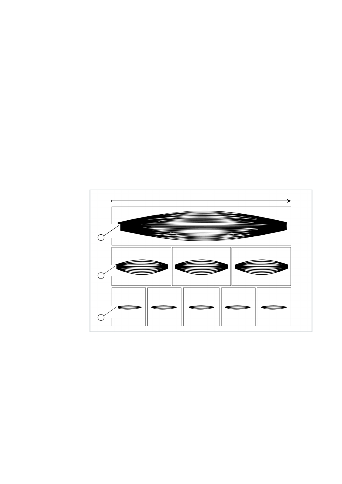
One of the scanners swivels with a constant amplitude thus generates the horizontal FoV (see
“3.3.6 Technical specifications” on page 17). The second scanner, which is responsible for
the vertical deflection, changes its amplitude continuously so that the entire vertical field-of-
view of the Cube is scanned and measured. The resulting scan pattern is similar to an ellipse
(see “Fig. 4 Field-of-view” on page13) whose vertical size changes. The opening and closing
process repeats at the frame rate. One complete scan of the scene is called a frame.
12
Fig. 4 Field-of-view
1 Window
2 Emission range of the laser
Product overview
14 Cube , Cube Range Version 2.1
3.3.3 Scan pattern
The scan pattern consists of vertically arranged, individual scan lines. Their angular spacing or
distribution is calculated by dividing the vertical FoV by the number of scan lines. For example,
a vertical FoV of 30° and 100 scan lines yield a vertical resolution of 0.3°.
The frame rate also depends on the number of scan lines. It describes how often the total scene
is scanned per second. The installed beam deflection unit permits a scan rate of 500 scan
lines/s. In the above example, this results in a frame rate of 500/100 1/s = 5 Hz. “Fig. 5 Scan
pattern” on page 14 illustrates the relationship between the number of scan lines and the
frame rate.
The straight edges that limit the horizontal FoV on both sides are intended to protect the eyes.
Another possible setting is the horizontal resolution, which describes the spacing between
two laser pulses along a scan line in the angular range, see “3.1.3 Function description” on
page11.
1
2
3
1 s
Fig. 5 Scan pattern
1 30 scan lines, 1 Hz
2 10 scan lines, 3 Hz
3 6 scan lines, 5 Hz
The figure shows scan patterns with different numbers of scan lines. The more scan lines are
configured, the longer it takes to measure a complete image.

Product overview
Version 2.1 Cube , Cube Range 15
3.3.4 Point cloud output
The primary data output of the Cube is a 3D point cloud, which is refreshed at a certain frame
rate that depends on the configured resolution and field-of-view. The point cloud is the collec-
tion of registered laser pulse reflections caused by objects within the field-of-view. The distance
to these objects is determined via the time-of-flight principle and combined with the deflection
angle information from the laser scanner to give the exact return locations in the three spatial
coordinates (X, Y, Z). For every received echo the following information are available:
Data field Description Data type
ID Unique identifier for every received echo. unit32
Cartesian coordinates Coordinates (x, y, z) relative to the Cube from
which the echo has been received.
float
Distance Distance from the Cube to where the target has
been located.
float
Intensity Relative intensity of the reflected light pulse. unit32
Tab. 3 LiDAR output data provided for every received echo
Additionally, the following data are available for every measurement angle:
Data field Description Data type
Timestamp offset Specifies the start of each ranging measure-
ment with respect to the absolute start time of
the corresponding frame in ns.
unit64
Elevation angle Elevation angle under which the measurement
was performed.
float
Azimuthal angle Azimuthal angle under which the measurement
was performed.
float
Ambient light level Provides a relative measure of the near infra-
red light intensity in that part of the scene. For
instance, objects illuminated directly by the sun
will show high ambient light values while dark-
ness will show low values.
unit32
Tab. 4 LiDAR data output provided for every measurement angle
Apart from the high-quality 3D point cloud data, the Cube outputs data of the integrated
inertial measurement unit (IMU), timing data, and device status data. For a full overview of the
retrievable data, please visit the user documentation of the Blickfeld Scanner Library under
https://docs.blickfeld.com/cube/latest/bsl_index.html.

Product overview
16 Cube , Cube Range Version 2.1
3.3.5 Coordinate system
The LiDAR point cloud data contains the Cartesian coordinates (x, y, z) of all detected echoes
per frame. Additionally, the coordinates are available in spherical coordinates (R, θ, ϕ), where R
is the distance from the sensor, θis the elevation angle, and ϕthe azimuthal angle. The defini-
tions of the two coordinate systems are depicted in “Fig. 6”. The following relationships apply
for converting between the coordinate systems:
x= R× cos θ × sin ϕ
y= R× cosθ × cosϕ
z= R× sin θ
Fig. 6 Cube coordinate system. Definitions and measurements of the origin
location are identical for Cube Range

Product overview
Version 2.1 Cube , Cube Range 17
3.3.6 Technical specifications
OPTICAL PERFORMANCEa
Cube Cube Range
Typical application range 1.5 – 75 m 5 – 150 m
Detection range 250 m (> 30 m for 10 %
reflectivity target,
pixel-filling, 100 klux,
90 % detection rate,
false positive rate <0.2 %,
0.6° horizontal angular
spacing)
250 m (> 50 m for 10 %
reflectivity target,
pixel-filling, 100 klux,
90 % detection rate,
false positive rate <0.2 %,
0.36° horizontal angular
spacingb)
Range resolution < 1 cm
Maximum field-of-view
(Horizontal x vertical)
70° x 30° 18° x 12°
Vertical resolution 5 – 400 scan lines per framec
(user-configurable)
5 – 200 scan lines per framec
(user-configurable)
Horizontal resolution 0.4° – 1.0°
(user-configurable)
0.24° – 0.4°
(user-configurable)
Scan rate > 500 scan lines per second
Frame rate 1.5 – 50 Hz (dependent on
configured scan lines and
vertical field-of-view)
Examples:
• 70° x 30°, 200 scan lines,
min. 2.5 Hz.
• 70° x 25°, 50 scan lines,
min. 10 Hz.
• 70° x 10°, 20 scan lines,
min. 25 Hz.
2.5 – 50 Hz (dependent on
configured scan lines and
vertical field-of-view)
Examples:
• 18° x 12°, 200 scan lines,
min. 2,5 Hz.
• 18° x 12°, 32 scan lines,
min. 15 Hz.
• 18° x 8°, 16 scan lines,
min. 30 Hz.
Number of returns 3d3
aMeasured at 25°C, 60% rel. humidity, single return.
bThe effective detection range drops at the edges of the field-of-view.
cFor less than 26 scan lines (Cube), respectively 18 scan lines (Cube Range) a reduced vertical
field-of-view must be configured (see frame rate).
dStarting from a distance of 5m. Only single returns at closer distances.

Product overview
18 Cube , Cube Range Version 2.1
LASER
Cube Cube Range
Laser class Class1, eye-safe (IEC60825-1:2014, Ed. 3)
Wavelength 905 nm
Beam divergence 0.4°
Examples:
• 10 m: 0.07 m x 0.07 m
• 50 m: 0.35 m x 0.35 m
0.24°
Examples:
• 10 m: 0.04 m x 0.04 m
• 100 m: 0.38 m x 0.38 m
OUTPUT
Cube Cube Range
Connection TCP/IP over Gigabit Ethernet
LiDAR output Distance, intensity, and Cartesian coordinates per return;
Azimuth angle, elevation angle, and timestamp in ns per
acquisition
On-device data processing Smart background subtraction and pose correction
transformation; Filters: Distance, Noise, Intensity, Neighbor
IMU output > 1 kHz sampling rate;
3-axis accelerometer, 3-axis gyroscope
CONTROL INTERFACE
Cube Cube Range
Configuration interface Cross-platform graphical web interface with interactive 3D
point cloud visualization and recording feature.
Control & stream interface TCP connection with Blickfeld protocol;
C++ library and Python package as client software interface;
ROS drivers available on request
Time synchronization NTPv4 and PTPv2 (IEEE 1588)

Product overview
Version 2.1 Cube , Cube Range 19
MECHANICALELECTRICAL
Cube Cube Range
Power consumption Typ. 8.5 W (max. 15 W)
Operating voltage Recommended: 12 V DC
Absolute maximum ratings:
• Min.: 10 V
• Max.: 26 V
Dimensions (H x W x D) 60 x 82 x 50 mm60 x 82 x 86 mm
Weight ca. 275 g ca. 385 g
Data connector Ethernet, RJ45
Power connector Phoenix Contact 1817615
Compatible power supply connector:
Phoenix Contact 1845219
Electromagnetic
compatibility
EN 61326-1:2013
• Emissions: Class B (Residential area)
• Immunity: Table 2 (Industrial Applications)
Electrical safety EN 61010-1:2020-03
Protection class III (SELV)
Overvoltage category I
OPERATIONAL
Cube Cube Range
Operating air temperature
(angle mount attached)
-30 °C – 60 °C
Storage temperature -30 °C – 60 °C
Humidity 85 % at 30 °C, non-condensing
Altitude 4000 m above sea level
Ingress protection IP40 according to (IEC 60529)
Pollution degree 2
Impact protection IK06 according to IEC 62262*
*The product has been tested and confirmed to be safe under the following conditions:
•Rated impact energy: 1 Joule.
•The housings of the product were cooled down to -30 °C and tested within the first 10 min-
utes after cooling.
•A steel sphere with a mass of 500 g ± 25 g and a diameter of ca. 50 mm was dropped onto
the product from a height of 200mm.

Installation
20 Cube , Cube Range Version 2.1
4 Installation
4.1 Scope of supply
Each Cube delivery contains the following parts:
•Ordered version of the Cube
•12 V DC power supply unit with the appropriate connector
•Ethernet cable (Cat. 6a)
•L-shaped mounting bracket
4.2 Mounting
The Cube may only be operated after it has been installed on a mount. The supplied aluminum
mounting bracket can be used for this (see “Fig. 7 Example of the Cube mounted on a tripod
using the supplied mounting bracket” on page21), or a mount prepared by the user can be
used as well. The mount must be designed in such a way that it dissipates the heat generated
by the Cube.
ATTENTION Electromagnetic radiation can damage the Cube.
•Do not place the Cube in the immediate vicinity of sources of
strong electromagnetic fields or strong magnets.
Other manuals for Cube 1
1
This manual suits for next models
1
Table of contents


