BLIIoT BL303 User manual
Embedded ARM Computer
BL303 BL304
BL303/304
User Manual
Version: V1.0
Date: 2023-8-1
Shenzhen Beilai Technology Co.,Ltd
Website: https://www.bliiot.com

Page 2of 38 Pages Shenzhen Beilai Technology Co., Ltd V1.0
Embedded ARM Computer BL303 BL304
Preface
Thanks for choosing BLIIoT Embedded ARM Computer BL303 BL304. These operating instructions
contain all the information you need for operation of a device in the EdgeCOM BL30 family.
Copyright
This user manual is owned by Shenzhen Beilai Technology Co., Ltd. No one is authorized to copy,
distribute or forward any part of this document without written approval of Shenzhen Beilai
Technology. Any violation will be subject to legal liability.
Disclaimer
This document is designed for assisting user to better understand the device. As the described
device is under continuous improvement, this manual may be updated or revised from time to time
without prior notice. Please follow the instructions in the manual. Any damages caused by wrong
operation will be beyond warranty.
Revision History
Revision Date
Version
Description
Owner
2023/8/1
V1.0
Initial Release
LKY

Page 3of 38 Pages Shenzhen Beilai Technology Co., Ltd V1.0
Embedded ARM Computer BL303 BL304
Table of Contents
1 Introduction................................................................................................................................................ 5
1.1 Overview.............................................................................................................................................5
1.2 Features..............................................................................................................................................5
1.3 Application scenarios........................................................................................................................ 5
1.4 Technical Specifications................................................................................................................... 6
1.5 Model Selection................................................................................................................................. 8
2 System Programming.............................................................................................................................. 9
2.1 Settings............................................................................................................................................... 9
2.2 Programming via TF Card................................................................................................................9
2.3 Programming via OTG....................................................................................................................12
2.3.1 Programming with Linux......................................................................................................... 12
2.3.2 Programming with Windows...................................................................................................12
3 Hardware Specifications........................................................................................................................14
3.1 Power Interface................................................................................................................................14
3.2 LED Indicators................................................................................................................................. 14
3.3 RS485&RS232 Serial Port.............................................................................................................15
3.4 CAN Interface.................................................................................................................................. 16
3.5 PWM Interface................................................................................................................................. 18
3.6 DI........................................................................................................................................................19
3.7 LAN....................................................................................................................................................20
3.8 WiFi Module..................................................................................................................................... 23
3.8.1 STA Mode..................................................................................................................................23
3.8.2 AP Mode .................................................................................................................................... 25
3.9 4G...................................................................................................................................................... 25
3.10 USB Port.........................................................................................................................................28
3.11 Debug..............................................................................................................................................29
3.12 SD Card slot...................................................................................................................................29
3.13 SIM Card Slot................................................................................................................................ 30
3.14 Antenna Interface.......................................................................................................................... 31

Page 4of 38 Pages Shenzhen Beilai Technology Co., Ltd V1.0
Embedded ARM Computer BL303 BL304
3.15 Reset Button.................................................................................................................................. 31
3.16 HDMI............................................................................................................................................... 32
4 Software................................................................................................................................................... 33
4.1 Login..................................................................................................................................................33
4.2 Time Setting..................................................................................................................................... 34
4.3 MCU Frequency Modulation..........................................................................................................35
4.4 Temperature Control....................................................................................................................... 35
4.5 Wake From Sleep............................................................................................................................36
4.6 Node-Red......................................................................................................................................... 37
4.7 SQLite............................................................................................................................................... 37
4.8 Python............................................................................................................................................... 37
4.9 QT...................................................................................................................................................... 37
4.10 MySQL............................................................................................................................................ 37
4.11 Ignition.............................................................................................................................................37
4.12 Docker.............................................................................................................................................37
4.13 Eclipse............................................................................................................................................ 37
4.14 Debian.............................................................................................................................................37
4.15 Ubuntu............................................................................................................................................ 38
5 Firmware update.....................................................................................................................................38
6 Warranty Terms...................................................................................................................................... 38
7 Technical Support...................................................................................................................................38

Page 5of 38 Pages Shenzhen Beilai Technology Co., Ltd V1.0
Embedded ARM Computer BL303 BL304
1 Introduction
1.1 Overview
The BL303/BL304 series Embedded ARM Computer use NXP i.MX8M Mini Quad-core 64-bit
processor, running speed up to 1.8GHz, with advanced ARM 4-core Cortex-A53 architecture, 2GB
DDR4 RAM, support one general-purpose Cortex®-M4 400MHz core processor, 8G eMMC.
BL304 comes with 4 RS485 or RS232, 1 CAN port, 2 Ethernet ports, 2 DI, 2 PWM output and 2 USB
port, 1 power input/output port, 1 HDMI, 1 Mini PCIe expansion slot for a wireless module.
The computer supports LINUX, Ubuntu, Debian, Node-Red, QT, Python, C++; MySQL, InfluxDB,
SQLite, Docker, Ignition, and Eclipse. This tiny embedded computer is widely applicable to a variety
of industrial solutions.
1.2 Features
NXP i.MX8M Mini processor, ARM Cortex-A53 architecture
Comes with Ethernet ports, RS485 or RS232 serial ports
1 Mini PCIe expansion slot for 4G/WiFi module
Supports LINUX, Ubuntu, Debian; Node-Red, QT, Python, C++; MySQL, InfluxDB, SQLite;
Docker, Ignition, Eclipse.
Automatic frequency reduction or restart when the chip is overheated
Chip frequency can be adjusted manually
Multiple sleep modes, with timing wake-up function
IP30 protection; metal shell and system are safely isolated; DIN rail installation
110mmx43mmx83mm(LxWxH) tiny embedded computer
1.3 Application scenarios
BL303/BL304 series Embedded ARM Computer are widely applicable to IoT, Industrial IoT, digital
factories, industrial automation, energy monitoring, smart security, rail transit, telecommunications,
smart EV charging, human-computer interaction and other fields.

Page 6of 38 Pages Shenzhen Beilai Technology Co., Ltd V1.0
Embedded ARM Computer BL303 BL304
1.4 Technical Specifications
Item
Parameter
Description
System
Processor
i.MX8M Mini Quad-Core 64-bit, 1.8HGz
RAM
2GB DDR4
Flash
8GeMMC
Power
Input Voltage
DC 9~36V
Power
Consumption
Normal: 360mA@12V, MAX 550mA@12V
Wiring
Anti- Inverse Connection Protection
Ethernet Port
Interface Spec
2 x RJ45, 1x10/100Mbps, 1x10/100/1000Mbps, adaptive
MDI/MDIX
Protection
ESD ±16kV (contact), ±18kV (air),
EFT 40A (5/50ns),
Lightening 6A (8/20µs)
Serial Port
QTY
4 x RS485/ RS232
Baud Rate
300bps-115200bps
Data Bit
7, 8
Parity Bit
None, Even, Odd
Stop Bit
1, 2
Protection
ESD ±8kV (contact), ±15kV (air)
EFT 2KV, 40A (5/50ns)
CAN Port
QTY
1
MAX Speed
1Mbps
SIM Card
QTY
2 SIM Card Slot
Spec
Drawer type slot, support 1.8V/3V SIM/UIM card (NANO)
Protection
Built-in 15KV ESD Protection
Digital Input
QTY
2
Input Type
Both Dry contact and Wet contact(NPN)
Dry Contact
Close: Short circuit
Open: Open circuit
Wet Contact
Logic 0: 0-2.5VDC
Logic 1: 10-30VDC
Isolation
protection
2KVrms
Digital Output
QTY
2
Output Type
PWM

Page 7of 38 Pages Shenzhen Beilai Technology Co., Ltd V1.0
Embedded ARM Computer BL303 BL304
USB Port
QTY
1xmicro USB, 2x USB2.0
Protection
Over Current Protection
SD Card Slot
QTY
1
Spec
Supports SD, SDHC and SDXC (UHS-I) cards
HDMI
QTY
1
Antenna
QTY
1x Cellular antenna, 1xWiFi Antenna
Type
SMA Hole Type
4G Module
(Optional)
L-E version
GSM/EDGE:900,1800MHz
WCDMA:B1,B5,B8
FDD-LTE:B1,B3,B5,B7,B8,B20
TDD-LTE:B38,B40,B41
L-CE version
GSM/EDGE:900,1800MHz
WCDMA:B1,B8
TD-SCDMA:B34,B39
FDD-LTE:B1,B3,B8
TDD-LTE:B38,B39,B40,B41
L-A version
WCDMA:B2,B4,B5
FDD-LTE:B2,B4,B12
L-AU version
GSM/EDGE:850,900,1800MHz
WCDMA:B1,B2,B5,B8
FDD-LTE:B1,B3,B4,B5,B7,B8,B28
TDD-LTE:B40
L-AF version
WCDMA:B2,B4,B5
FDD-LTE:B2,B4,B5,B12,B13,B14,B66,B71
CAT-1 version
GSM:900,1800
FDD-LTE:B1,B3,B5,B8
TDD-LTE:B34,B38,B39,B40,B41
WiFi(Optional)
Interface
PCIe
Protocol
IEEE 802.11b/g/n
Mode
STA, AP
Frequency
2.4GHz
Channel
Ch1 ~ Ch13
Security
Open, WPA, WPA2
Encryption
AES, TKIP, TKIPAES
Connection
8(Max)
Speed Rate
150Mbps(Max)
Transmission
distance
Outdoor/Open area, up to 20 meters
SSID
Support

Page 8of 38 Pages Shenzhen Beilai Technology Co., Ltd V1.0
Embedded ARM Computer BL303 BL304
Indicator
QTY
LEDx8
Environment
Working
0~70℃, 10~90% RH
Others
Case
Metal Case
Size
110mmx43mmx83mm(LxWxH)
Protection
IP30
Mounting
DIN-Rail Mounting
1.5 Model Selection
Model
BL303
BL304
BL303T
BL304T
Processor
iMX8M
iMX8M
iMX8M
iMX8M
CPU Frequency
MAX 1.8GHz
MAX 1.8GHz
MAX 1.6GHz
MAX 1.6GHz
RAM
2G DDR4
2G DDR4
2G DDR4
2G DDR4
Flash
8G eMMC
8G eMMC
8G eMMC
8G eMMC
ETH
1x100M, 1x1000M
1x100M, 1x1000M
1x100M, 1x1000M
1x100M, 1x1000M
USB
2
2
2
2
RS232/RS485
2
4
2
4
CAN
x
1
x
1
SD slot
1
1
1
1
MINI-PCIe
x
1
x
1
4G(GPS)/WIFI
x
√
x
√
SIM slot
x
2
x
2
HDMI
1
1
1
1
DI
x
2
x
2
DO
x
2
x
2
Temperature
0℃~70℃
0℃~70℃
-40℃~70℃
-40℃~70℃
Page 9of 38 Pages Shenzhen Beilai Technology Co., Ltd V1.0
Embedded ARM Computer BL303 BL304
2 System Programming
2.1 Settings
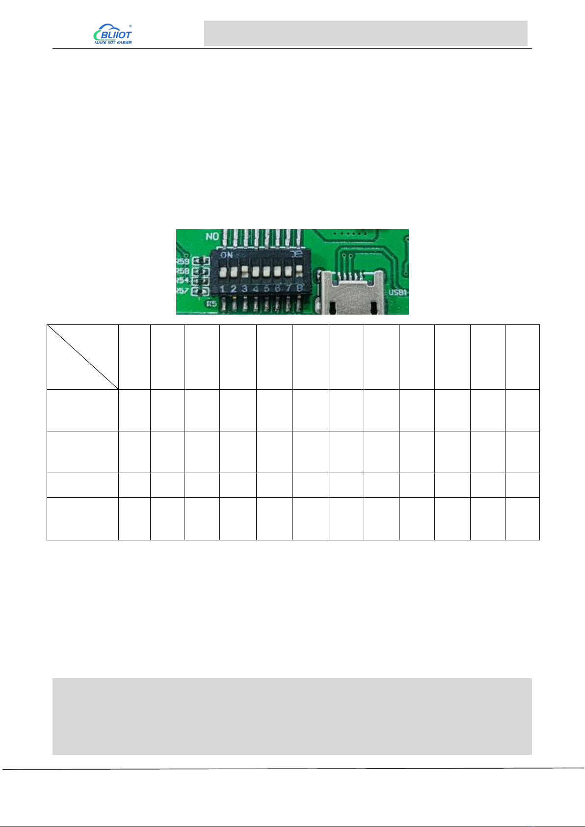
The computer supports USB OTG and TF card programming, supports eMMC and QSPI startup, DIP
switche K5 is located on the side of the mini-usb port and K3 is located on the back of the core board
where the network port is located. K3 is all OFF by default, and uses DIP switch (K5) to distinguish
different operation methods (eMMC startup as shown in the figure below)
Mode
Switch
(K3)
1
(K3)
2
(K3)
3
(K3)
4
(K3)
5
(K3)
6
(K3)
7
(K3)
8
(K5)
1
(K5)
2
(K5)
3
(K5)
4
eMMC
startup
OFF
OFF
OFF
OFF
OFF
OFF
OFF
OFF
OFF
OFF
ON
OFF
TF
Programming
OFF
ON
OFF
OFF
OFF
ON
ON
ON
ON
OFF
ON
OFF
QSPI startup
ON
OFF
ON
OFF
ON
OFF
OFF
OFF
ON
ON
ON
OFF
OTG
Programming
X
X
X
X
X
X
X
X
X
X
OFF
ON
2.2 Programming via TF Card
When using a TF card to programming, please use a genuine card with a capacity of 8G and above
to test, and the format should be FAT32 format.
Creating a TF card
Copy the folder sdfuse to the VM TF card insert it into the VM and go to the folder.
ubuntu:~$ cd imx8mm/sdfuse/
ubuntu:~/imx8mm/sdfuse$ sudo ./mksdcard8mm.sh
[sudo] password for forlinx: //Need to enter forlinx No display of password:forlinx, Press enter to co
ntinue
[…]

Page 10 of 38 Pages Shenzhen Beilai Technology Co., Ltd V1.0
Embedded ARM Computer BL303 BL304
Availible Drives to write images to:
# major minor size name
1: 8 16 15558144 sdb
Enter Device Number: 1//Select TF card device, enter 1
sdb was selected1
Checking the device is unmounted
unmounting device '/dev/sdb1'
Would you like to re-partition the drive anyways [y/n] : y//Enter "y" to confirm
Now partitioning sdb ...
###########################################################################
Now making 1 partitions
###########################################################################
1+0 records in
1+0 records out
1024 bytes (1.0 kB, 1.0 KiB) copied, 0.00133858 s, 765 kB/s
DISK SIZE - 1024 bytes
[…]
###########################################################################
Partitioning Boot
###########################################################################
mkfs.fat 3.0.28 (2015-05-16)
mkfs.fat: warning - lowercase labels might not work properly with DOS or Windows
Buring th sdfuse.bin to sdcard
1359+1 records in
1359+1 records out
1392324 bytes (1.4 MB, 1.3 MiB) copied, 0.00231964 s, 600 MB/s
Syncing....
unmounting device '/dev/sdb1'
Print the information as shown above, indicating that the TF card has been successfully created. After
making the card according to the script at this time, the TF card will be uninstalled automatically. If
you want to make the card and still mount it on the development environment, you need to modify the
card making script.
mksdcard8mm.sh:
ubuntu:~/imx8mm/sdfuse$ vi mksdcard8mm.sh
[…]
for i in `ls -1 $DRIVE?`; do
echo "unmounting device '$i'"
#umount $i 2>/dev/null //Comment out this command at the end of the script
done
Page 11 of 38 Pages Shenzhen Beilai Technology Co., Ltd V1.0
Embedded ARM Computer BL303 BL304
Copy the image to the TF card, the specific options to be copied are listed in the table below
File
Description
config.ini
Programming configuration files, in the tools directory
update.itb
Programming tools, in the tools directory
flash_qspi.bin
U-Boot-QSPI image, when you need to programming the QSPI image
in the development board, put this image into the TF card (optional)
env.ini
Write additional environment variables to uboot (optional)
m4_flash.bin
M4 Mirror Image (optional)
rootfs.sdcard
Image package, contains uboot and kernel, if you are using the original
uboot, then just put this one into the TF card.
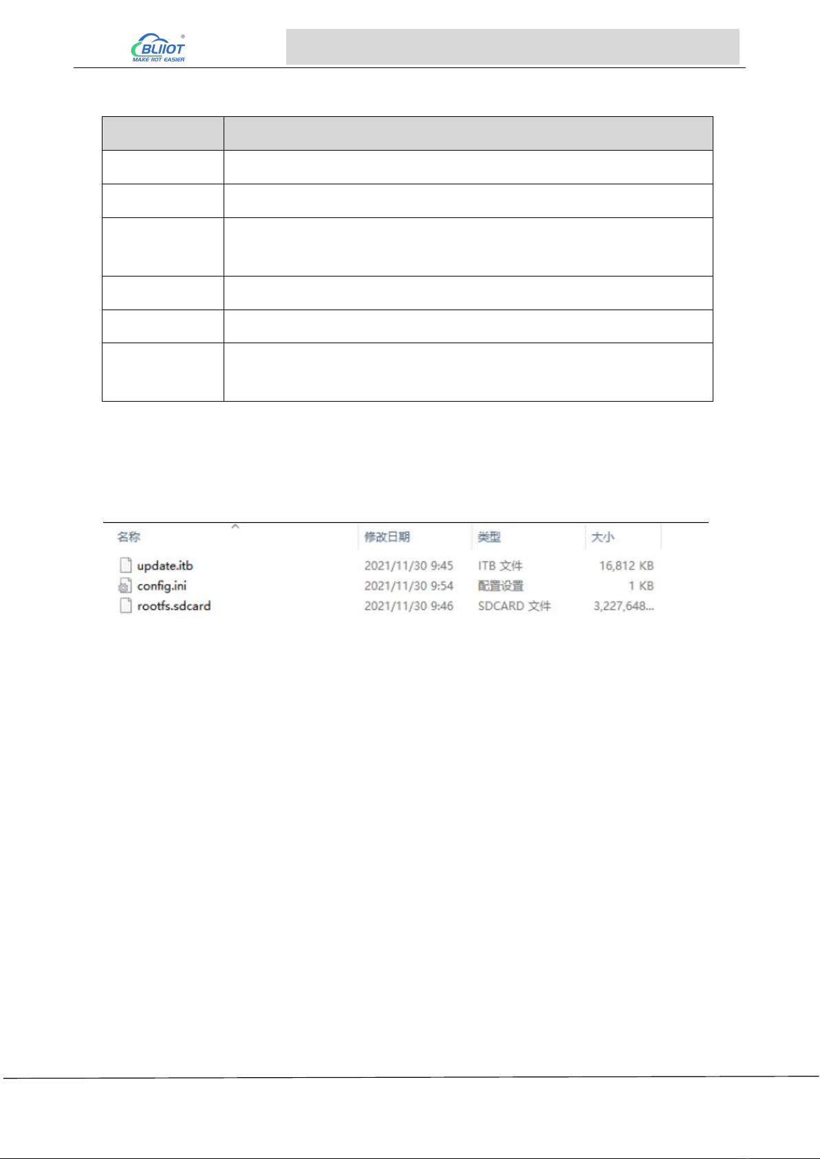
Mount the TF card to the computer, copy the rootfs.sdcard and update.itb under the image file in the
windows system to the finished TF, and then copy the config.ini under the tool\sdfuse folder to the TF
card. The content of the finished TF is shown below:
Insert the TF card into the device, turn switches 1 and 3 of K5 to ON, and 2, 6, 7 and 8 of the other
switch (on the back) to ON. Turn on the power switch, and the device will automatically start to enter
the programming program.
Other Notices
If you are using A-core uboot, unmodified, just put rootfs.sdcard in the TF card, which contains
the standard uboot image.
If m4_flash.bin exists, it will be automatically programmed into qspi flash for QSPI boot of M-core,
and m4_flash.bin will be burned into emmc with 5M offset at the same time. If m4_flash.bin does
not exist, and flash_qspi.bin exists, it will be automatically burned into qspiflash for QSPI booting,
and if it does not exist, it will not be burned by default.
When using the TF card to burn, you can add a text named env.ini to the TF card, during the
burning process, the burning program reads the environment variables by line, and the
environment variables that meet the format will be appended to the default environment
variables. env.ini has one environment variable for each line, and the format is: the name of the
environment variable = the value of the environment variable.
Users programming the already compiled image into the storage media during the TF card

Page 12 of 38 Pages Shenzhen Beilai Technology Co., Ltd V1.0
Embedded ARM Computer BL303 BL304
programming process. The already compiled M4 image named m4_flash.bin can be put into the
TF card, and during the programming process, the M4 image will be programmed into the emmc
at an offset of 5M or the starting position of QSPI (QSPI Flash exists). Users can set the
environment variable m4_run to start the M4 image. For example compile the image to run M4
image on QSPI, set m4_run=sf probe; bootaux 0x8000000.
After Programming, if emmc mode startup report an error: [end kernel panic -not
syncing:Attempted to kill init!], it means that there is a problem with programming, not successful,
need to re-program.
2.3 Programming via OTG
Please use USB2
2.3.1 Programming with Linux
1. The command to burn uboot does not clear the environment variables; to restore the default
environment variables enter them on the uboot command line:
u-boot=> env default -a -f //Restore default environment variables
u-boot=> saveenv //Save Environment Variables
2. QSPI flash can only store one of the M4 image or the uboot image, not both.
3. m4_flash.bin is the M4 image compiled by the user.
Copy uuu from the tool file to the /usr/bin/ directory under the development environment and add
executable permissions; connect the device to the computer and turn dip switch 4 to ON.
ubuntu:~$ cd /home/forlinx/imx8mm/OK8MM-linux-sdk/images
(1) Programming system (u-boot, kernel and filesystem) to emmc:
ubuntu:~/imx8mm/OK8MM-linux-sdk/images$ sudo uuu -b emmc_all flash_sd_em\ mc.bin rootfs.sdcard
(2) Programming u-boot to emmc
ubuntu:~/imx8mm/OK8MM-linux-sdk/images$ sudo uuu -b emmc flash_sd_emmc.bin
(3) Programming u-boot to QSPI flash:
ubuntu:~/imx8mm/OK8MM-linux-sdk/images$ sudo uuu -b qspi flash_qspi.bin
(4) Programming M4 image to QSPI flash:
ubuntu:~/imx8mm/OK8MM-linux-sdk/images$ sudo uuu -b qspi flash_qspi.bin \
m4_flash.bin
2.3.2 Programming with Windows
Copy the uuu.exe file to the C:\Windows\System32 directory. Then extract the
platform-tools_r28.0.3-windows.zip file to C:\Windows\System32, or C:\Windows\SysWOW64 for

Page 13 of 38 Pages Shenzhen Beilai Technology Co., Ltd V1.0
Embedded ARM Computer BL303 BL304
64-bit windows systems.
Use OTG cable to connect the device to the computer, turn the 4 of the dip switch to ON to start the
device.
Create the uuu directory in D drive and copy the image into it, run the cmd program under Windows
to enter the directory where the image file is located, there are four kinds of programming commands,
corresponding to different ways of programming and different ways of programming the image, if you
are not clear about the difference, we suggest that you choose the first programming command
directly.
(1) Programming u-boot, kernel, and filesystem to emmc:
Microsoft Windows [Version 10.0.19042.1165]
(c) Microsoft Corporation. All rights reserved.
C:\Users\Administrator>D: //Go to disk D
D:\>cd uuu //Go to the uuu folder
D:\uuu> uuu.exe -b emmc_all flash_sd_emmc.bin rootfs.sdcard
(2) Programming u-boot to emmc:
Microsoft Windows [Version 10.0.19042.1165]
(c) Microsoft Corporation. All rights reserved.
C:\Users\Administrator>D:
D:\>cd uuu
D:\uuu> uuu.exe -b emmc flash_sd_emmc.bin
(3) Programming u-boot to QSPI flash:
Microsoft Windows [Version 10.0.19042.1165]
(c) Microsoft Corporation. All rights reserved.
C:\Users\Administrator>D:
D:\>cd uuu
D:\uuu> uuu.exe -b qspi flash_qspi.bin
(4) Programming M4 image to QSPI flash:
Microsoft Windows [Version 10.0.19042.1165]
(c) Microsoft Corporation. All rights reserved.
C:\Users\Administrator>D:
D:\>cd uuu
D:\uuu> uuu.exe -b qspi flash_qspi.bin m4_flash.bin

Page 14 of 38 Pages Shenzhen Beilai Technology Co., Ltd V1.0
Embedded ARM Computer BL303 BL304
3 Hardware Specifications
3.1 Power Interface
BL303/BL304 comes with 1 power input. Support DC 9~36V input, anti-reverse connection
protection.
3.2 LED Indicators
The following figures shows the LED indicators, and the order from left to right and from top to bottom
is LED6, LED5, LED1, LED2, LED8, LED7, LED3, LED4, correspondence with the LEDs in the
/sys/class/leds directory.
View trigger conditions:
root@okmx8mm:~# cat /sys/class/leds/led1/trigger
[none] rc-feedback nand-disk mmc0 timer oneshot heartbeat backlight gpio
Where [none] means the current trigger condition of led1 is none. Write the above string to trigger to

Page 15 of 38 Pages Shenzhen Beilai Technology Co., Ltd V1.0
Embedded ARM Computer BL303 BL304
modify the trigger condition.
When the led trigger condition is set to none, user can control the led light on or off by command.
root@okmx8mm:~# echo none > /sys/class/leds/led1/trigger
Control LED1 lights ON
root@okmx8mm:~# echo 1 > /sys/class/leds/led1/brightness
Controls LED1 lights OFF
root@okmx8mm:~# echo 0 > /sys/class/leds/led1/brightness
The other 7 led lights are similar, just change under /sys/class/leds to the one corresponding to the
corresponding ledx.
3.3 RS485&RS232 Serial Port
BL303/BL304 comes with RS485 or RS232. COM1, COM2, COM3 and COM4 are corresponding to
/dev/ttymxc0, /dev/ttymxc1, /dev/ttymxc3 and /dev/ttymxc2 respectively. The R485 serial port
supports a maximum baud rate of 115200 with a cable length of 200 meters.
For debugging, enter the following command:
busybox microcom -s 115200 /dev/ttymxc0
microcom: Command to test the serial port;
-s: Indicates the transmission speed, the baud rate is 115200;
/dev/ttymxc0: Refers to the serial port name of the specific device.
COM2 is the debugging serial port, if you need to use it, you need to convert it to a normal serial port.
Page 16 of 38 Pages Shenzhen Beilai Technology Co., Ltd V1.0
Embedded ARM Computer BL303 BL304
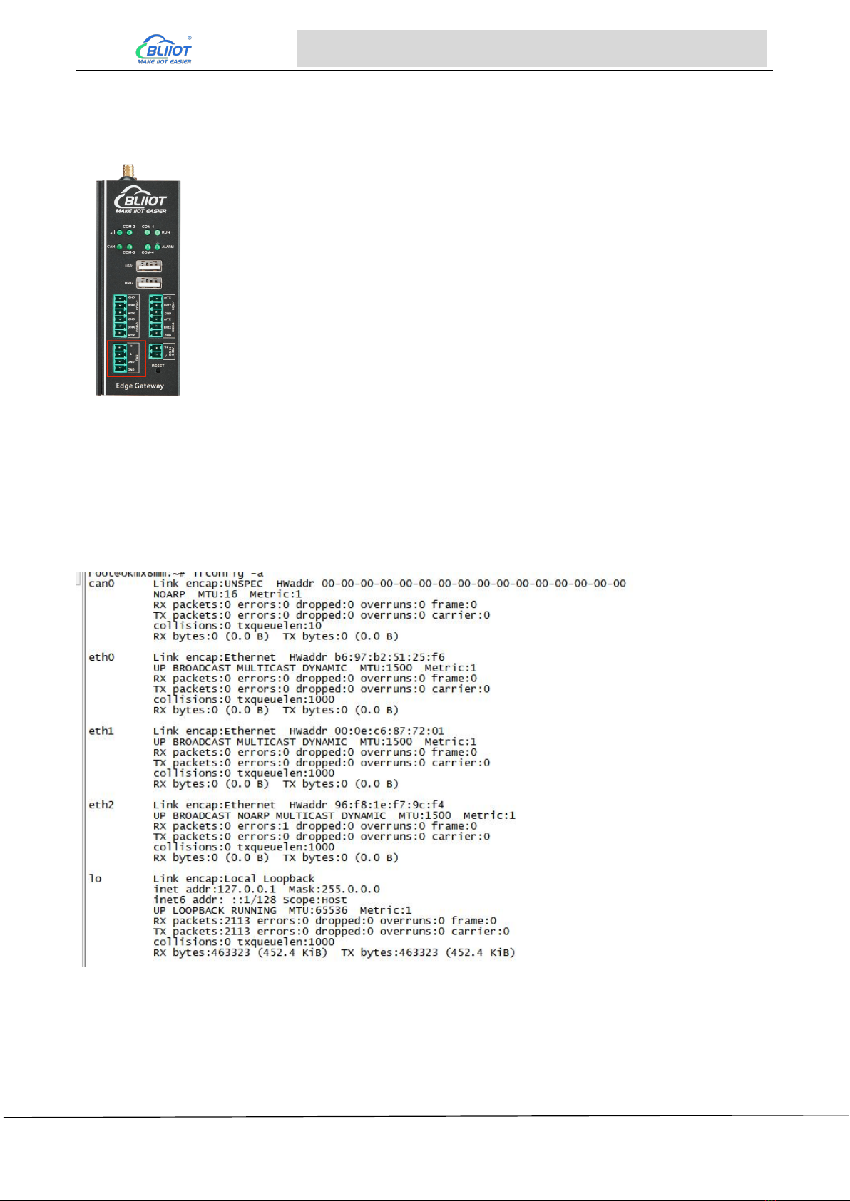
3.4 CAN Interface
The CAN interface is as shown in the figure, enter the following command:
ifconfig -a //View all network cards
If the FlexCAN driver works well, you will see the network card interface corresponding to CAN, as
shown in the figure, there is a network card named "can0", which is the CAN network card
corresponding to the CAN interface on the BL304 board.
CAN port usage example:
Connect the CAN ports of the two devices, note that CAN_H connects to CAN_H and CAN_L
connects to CAN_L.
First you need to turn CAN0 off
ifconfig can0 down

Page 17 of 38 Pages Shenzhen Beilai Technology Co., Ltd V1.0
Embedded ARM Computer BL303 BL304
Use the IP command to set the CAN interfaces of the two devices, first set the baud rate of the
CAN interface to 12500 and enter the command shown below:
ip link set can0 up type can bitrate 125000 triple-sampling on
The speed of the upper two CAN devices should be set to the same! After the speed is set open
the can0 card with the following command:
ifconfig can0 up //open can0
One device is used to receive data and one is used to send data. The device that receives data
uses the candump command. Enter the following command:
candump can0 //receive data
The device sending data uses the cansend command to send 8 bytes of data to the receiving
unit: 0X11, 0X22, 0X33, 0X44, 0X55, 0X66, 0X77, 0X88. Enter the following command:
cansend can0 5A1#11.22.33.44.55.66.77.88
cansend command is used to send CAN data, "5A1" is the frame ID, "11.22.33.44.55.66.77.88"
after "#" is the data to be sent, hexadecimal. CAN2.0 can send up to 8 bytes of data at a time,
and the 8 bytes of data are separated by a "."
If CAN is working correctly the receiver will receive the 8 bytes of data sent above.
root@okmx8mm:~# candump can0 //Receive data from can0
interface = can0, family = 29, type = 3, proto = 1
<0x010> [8] 11 22 33 44 55 66 77 88
From the above, it can be seen that the can0 interface on the receiver side received 8 bytes of
data with a frame ID of 5A1, indicating that the CAN driver is working properly.
If you want to close can0 enter the following command:
ifconfig can0 down
If you want to perform a CAN loopback test on a board, set up the CAN according to the
following command:
ifconfig can0 down //If can0 is already on, close it first
ip link set can0 type can bitrate 500000 loopback on //Open Loopback Test
ifconfig can0 up //Reopen can0
candump can0 & //candump backend receives data
cansend can0 5A1#11.22.33.44.55.66.77.88 //cansend send data
If the loopback test is successful then the device receives the data sent to itself as shown in the
figure:
/ # cansend can0 5A1#11.22.33.44.55.66.77.88
can0 5A1 [8] 11 22 33 44 55 66 77 88
Page 18 of 38 Pages Shenzhen Beilai Technology Co., Ltd V1.0
Embedded ARM Computer BL303 BL304
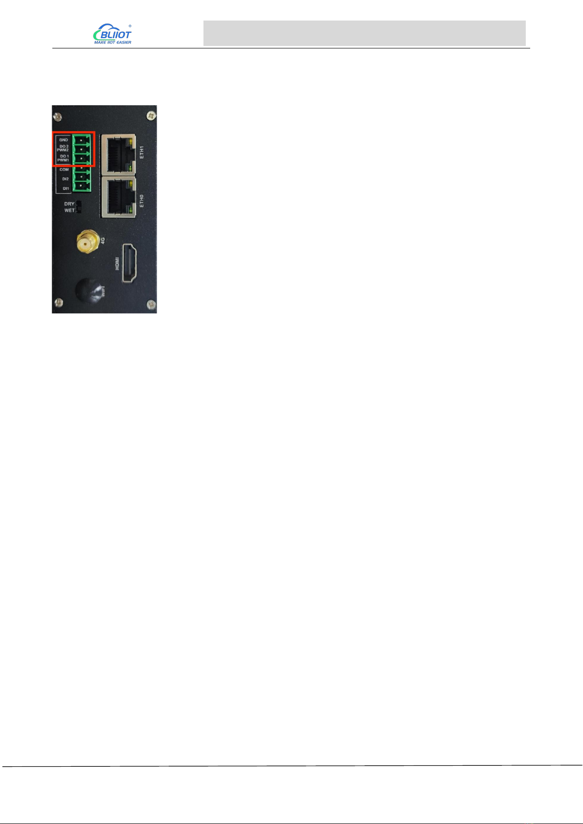
3.5 PWM Interface
The PWM port is shown in the figure. PWM devices are under the directory /sys/class/pwm, where
PWM1 and PWM2 are applied to pwmchip0 and pwmchip1.
Taking PWM1 as an example, first you need to call out the pwm0 directory under pwmchip0, and
enter the following command:
echo 0 > /sys/class/pwm/pwmchip0/export
After the execution is completed, a subdirectory named "pwm0" will be generated under the
pwmchip0 directory, as shown below
root@okmx8mm:/sys/class/pwm/pwmchip0# ls
device export npwm power subsystem uevent unexport
root@okmx8mm:/sys/class/pwm/pwmchip0# echo 0 > export
root@okmx8mm:/sys/class/pwm/pwmchip0# ls
device export npwm power pwm0 subsystem uevent unexport
Enable PWM1: Enter the following command to enable PWM1
echo 1 > /sys/class/pwm/pwmchip0/pwm0/enable
Set the frequency of PWM1: Note that the period value is set here, and the unit is ns. For example,
the period of 20KHz frequency is 50000ns. Enter the following command:
echo 50000 > /sys/class/pwm/pwmchip0/pwm0/period
Set the duty cycle of PWM1: You cannot set the duty cycle directly, please set the ON time of a cycle,
that is, the high-level time, for example, the ON time of 20% duty cycle at 20KHz frequency is 10000,
enter the following command
echo 10000 > /sys/class/pwm/pwmchip0/pwm0/duty_cycle
Page 19 of 38 Pages Shenzhen Beilai Technology Co., Ltd V1.0
Embedded ARM Computer BL303 BL304
If you need to adjust the frequency or duty cycle, pay attention to the high-level time when adjusting.
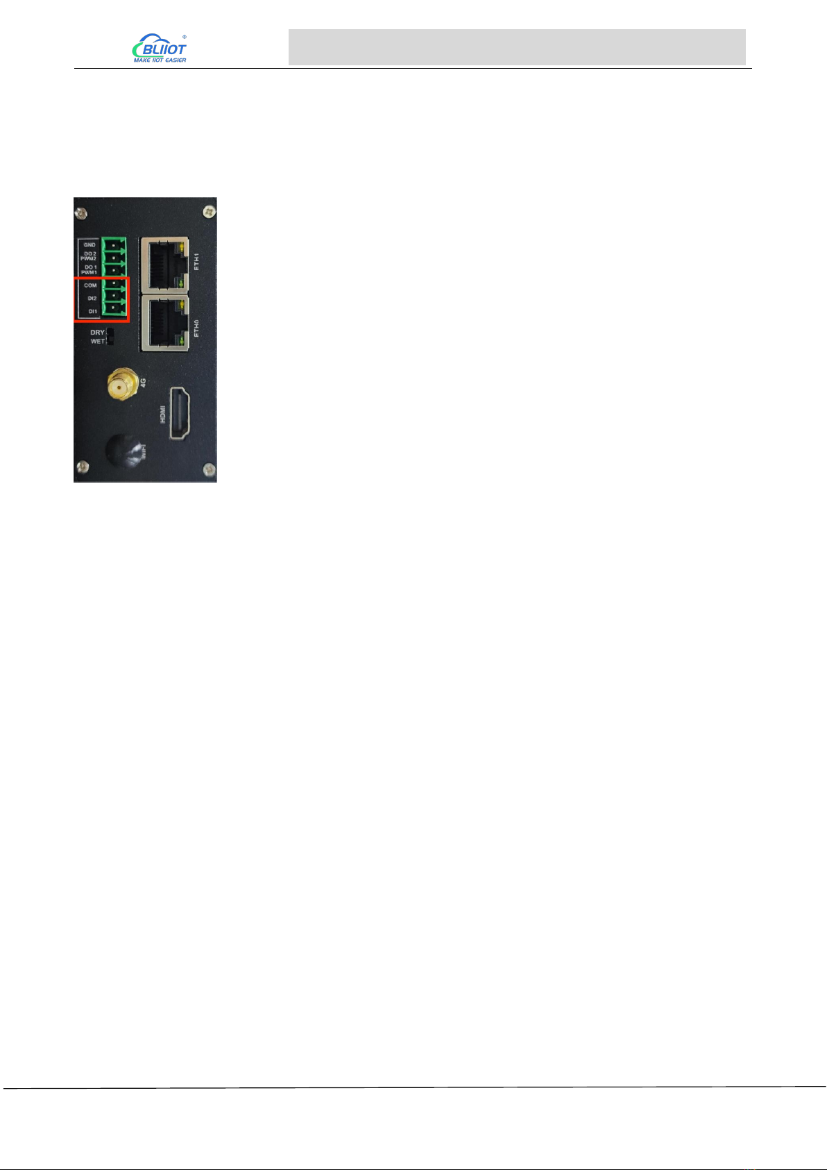
3.6 DI
The devices corresponding to DI1 and DI2 are gpio_input_0 and gpio_input_1 respectively. Select
the dry/wet contact mode by the switch below.
Take DI1 as an example, when debugging the DI interface, enter the command:
./inputapp /dev/gpio_input_0
When the dry contact mode is selected, the port is shorted; when the wet contact mode is selected,
the input is greater than 3V; the console output is as follows:
root@okmx8mm: /opt# ./input64 /dev/gpio_input_0
di value = 0x1

Page 20 of 38 Pages Shenzhen Beilai Technology Co., Ltd V1.0
Embedded ARM Computer BL303 BL304
3.7 LAN
There are eth0 and eth1 network cards on the bottom board of BL304. When the power is just turned
on and the startup is complete, if the network cable is not inserted, you can see that the network port
has no IP address with ifconfig. This is because dhcp dynamically allocates ip, when network cable is
inserted, the console will print the corresponding Ethernet, and you can check the corresponding IP
address with ifconfig.
Software equipment
Supported Speed
ETH1
10/100Mbps
ETH0
10/100/1000Mbps
Note: eth1 and eth0 cannot be used in the same LAN.
Take eth0 as an example.
Under the Linux system, use the ifconfig command to display or configure network devices, and use
ethtool to query and set network card parameters.
Set the IP address and view the details of the current network card:
root@okmx8mm:~# ifconfig eth0 192.168.1.120 //set ip
root@okmx8mm:~# ifconfig eth0 //Check the network status after setting
eth0 Link encap:Ethernet HWaddr 3A:D9:93:8E:A8:A4
inet addr:192.168.1.120 Bcast:192.168.1.255 Mask:255.255.255.0
inet6 addr: fe80::38d9:93ff:fe8e:a8a4%2124311408/64 Scope:Link
inet6 addr: fec0::38d9:93ff:fe8e:a8a4%2124311408/64 Scope:Site
UP BROADCAST RUNNING MULTICAST MTU:1500 Metric:1
RX packets:28 errors:0 dropped:0 overruns:0 frame:0
TX packets:63 errors:0 dropped:0 overruns:0 carrier:0
collisions:0 txqueuelen:1000
RX bytes:11550 (11.2 KiB) TX bytes:11579 (11.3 KiB)
This manual suits for next models
1
Table of contents


