Blitz Audio BZX2 User manual

BZX-2
2-Way Electronic Crossover Network
w/Remote Subwoofer Level Control
user’s manual

Thank you for purchasing the Blitz High performance Electronic Crossover. Rest assured you have
purchased a quality product designed and engineered to give you many years un-compromised
musical service. The Blitz Electronic Crossover has been designed using the latest in electronic
technology available today.
When you check the list of features offered by the BZX-2, you'll know you made the right choice
with a Blitz Electronic Crossover network.
INTRODUCTION...

general features
precautions
features and specifications
system wiring
mounting and installation
noise check and system adjustment
troubleshooting
2
3
4-5
6
7
8
9
table of contents

Hi-pass Crossover Adjustable Frequency from 80 to 2.5KHz
Lo-pass Crossover Adjustable Frequency from 35 to 400Hz
Variable Bass Boost Level from 0 to 12dB
Subwoofer Phase Shift 0/180 degrees
Hi-pass Gain Control
Lo-pass Gain Control
Lo-pass Stereo/Mono Selector
LED Power On Indicator
Remote Power On/Off
Remote Subwoofer Level Control
2
general features

3
Precautions
To prevent short circuits, be sure to disconnect the negative battery ground lead before wiring the system up.
When you finish the installation, be sure to make one more check to be sure everything is done correctly.
Reinstate all car parts that were removed.
Reconnect the negative battery ground lead.
Primary Wiring Descriptions
ELECTRICAL PRIME CONNECTION DESCRIPTION
12V
GROUND
REMOTE
INPUT
HIGH PASS
OUTPUT
LOW PASS
OUTPUT
BATTERY +
GROUND -
REMOTE B +
RADIO/TAPE
PLAYER TO
CROSSOVER MODULE
CROSSOVER MODULE
TO ANY AMPLIFIER
CROSSOVER MODULE
TO SUB-WOOFER AMPLIFIER
Connect to the positive battery terminal (constant + 12V
source)
Connect to the vehicle’s chassis ground (check for good
ground)
Connect to the remote control wire (or the electrical
antenna) of the car radio/cassette deck.
Connect from pre-amp output of radio/tape player (or
CD) into
Connect from "high-pass output" of CROSSOVER module
to any amplifier input.
Connect from low-pass sub-woofer output of CROSSOVER
to sub-woofer amplifier input.

4
features and specifications

5
features and specifications
Power source
Input current
Distortion
Frequency response
S/N ratio (A weighted)
Separation
Crossover frequencies
(continuously variable)
Low-pass
High-pass
Crossover slope rate
Subwoofer boost
Input impedance
Output impedance
Output voltage level
Dimensions
14.4 volts DC negative ground
0.5 amp max
0.01% THD at 1 V output level
10Hz-30KHz
±
3 dB
> 95dB
60 dB
35-400 Hz
80-2.5K Hz
12 dB per octave 2nd Order Butter worth
Single octave + 12dB at 45 Hz
> 10K Ohms
<1K Ohms
5 volts max
160mm (W) x 130mm (D) x 37mm (H)
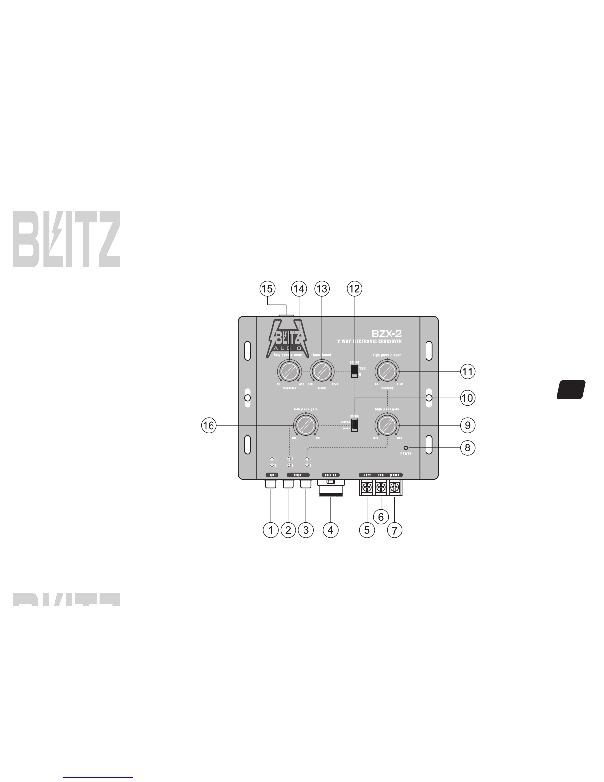
1.SIGNAL INPUTS
2.LOW PASS SUBWOOFER OUTPUT
TERMINALS
3.HIGH PASS CHANNEL OUTPUT
TERMINALS
4.FUSE
5.POWER INPUT TERMINAL (12V)
6.REMOTE TURN-ON INPUT TERMINAL
(REMOTE)
7.GROUND INPUT TERMINAL
8.POWER INDICATOR
9.HIGH PASS GAIN CONTROL
10.SUBWOOFER STEREO/MONO SWITCH
11.HIGH-PASS FREQUENCY SELECTOR
12.PHASE INVERTER
13.BASS-BOOST LEVEL CONTROL (45Hz)
14.LOW PASS SUBWOOFER FREQUENCY
SELECTOR
15.SUBWOOFER OUTPUT LEVEL REMOTE
CONTROL TERMINAL.
16.LOW PASS SUBWOOFER OUTPUT GAIN
CONTROL
To be connected to the output of the source unit.
To be connected to the subwoofer channel amplifier left/right inputs.
To be connected to the channel amplifier left/right inputs.
This crossover uses 1-amp, blade-type fuses for protection from power surges or a short
circuit.
To be connected to the positive terminal of your vehicle battery or other constant +12V source.
To be connected to the remote control wire or antenna lead of the source unit for remote
ON/OFF.
To be wired to the vehicle's chassis ground.
This indicator lights up when the internal switching power supply is activated and the unit
is operational.
For adjusting the channel output signal level.
For selection of stereo or mono mode subwoofer output.
For selection of high-pass crossover frequency between 80 Hz and 2.5KHz
Position the switch to the "180" position shifts the subwoofer output signals 180 degrees out-
of-phase relative to the front and rear output signals.
For increasing the Bass boost level up to +12dB.
For selection of the low-pass crossover frequency for the subwoofer channel between 35 Hz
and 400 Hz.
To be connected to the remote control for exclusive maneuver of the subwoofer output level,
and the subwoofer output level control on the unit ("16" below) is by-passed.
For adjusting the subwoofer channel output signal level.
FEATURES AND SPECIFICATIONS SUBJECT TO CHANGE AND / OR IMPROVEMENT WITHOUT NOTICE.

6
System wiring
TWEETER
WOOFER

7
Mounting and installation

8
Noise check and system adjustment
NOISE CHECK
Check the entire audio system for noise before permanently securing the CROSSOVER mounting
1. Start the engine.
2. Turn the audio system on.
3. Rev the engine and vary the VOLUME of the audio system to determine if there is any unwanted noise.
If so, turn both the audio system and the engine off. Do not secure the CROSSOVER mounting screws. Refer to the "Trouble Shooting Guide" at this
manual.
4. If the audio system does not have any noise, securely tighten the CROSSOVER mounting screw and double check the wiring cables for safe placement.
SYSTEM ADJUSTMENT
Preliminary Adjustments
Pre-setting the system provides a necessary starting point for fine-tuning the entire audio system to maximum performance.
NOTE: DO NOT MOUNT CROSSOVER UNTIL THE FOLLOWING PROCEDURES HAVE BEEN COMPLETED.
1. Preset each amplifier input gain adjustment at the amplifier to half of maximum.
2. Before turning the audio system on, preset-adjust the front, rear and sub-woofer output level controls, as well as the front channel high-pass and sub-
woofer channel low-pass crossover points.
3. Slowly turn the volume up and listen carefully for: obvious trouble in sound (distortion, no sound, no hiss, total silence). Turn the system off refer to
“Trouble Shooting Guide”at this manual.
Caution
DO NOT ROUTE AUDIO CABLES AND POWER CABLES TOGETHER! THIS CAN CAUSE ENGINE NOISE IN YOUR AUDIO SYSTEM.
ALWAYS DISCONNECT THE SYSTEM FROM THE BATTERY BEFORE ATTEMPTING TO MAKE OR ALTER ANY CONNECTIONS. THIS
PRODUCT IS DESIRED FOR USE IN ANY 12 VOLTS NEGATIVE GROUND ELECTRICAL SYSTEM ONLY. INSTALLING THIS PRODUCT
IN ANY POSITIVE GROUND ELECTRICAL SYSTEM COULD SERIOUSLY DAMAGE THE AUDIO SYSTEM.

9
TBOUBLE SHOOTING GUIDE
1. There is an audible distortion at a low
volume level.
PROBLEM POSSIBLE CAUSE
Output levels NOT set correctly.
2. A whining sound can be heard through the
speakers when the audio system is at low
volume with the engine running. The whining
noise remains unchanged or seems to
disappear when the volume level is
increased.
3. There is a "motor boating" type of sound
when the engine is running and the audio
system volume is set at a reasonably high
level.
Check the red power wire. It muse be connected
directly to the battery. Check the system's
ground point It muse make good contact with
chassis ground (bare metal).
The radio and the CROSSOVER must be
grounded at the same reference point.
Check the red power wire. It must be connected
directly to the battery. Check the system's
ground point. It must make good contact with
chassis ground (bare metal).

All Blitz products are carefully constructed and thoroughly tested before
shipment. Products purchased in the USA are warranted to be free of defects
in material and workmanship for two (2) years from the date of purchase. This
warranty is limited to the original retail purchase.
Should the product fail due to factory defects in material or workmanship,
your unit will be repaired or replaced at the sole discretion of Blitz.
To obtain warranty service you must first call our Consumer Return Hotline
number at (718) 236-6948 to obtain a Return Authorization number. This
R.A.# must appear on the outside of your package and on all paperwork
relating to your return.
When returning a product to us for warranty service it must be carefully packed
and shipped prepaid to:
You must also include the following items:
•A copy of your sales receipt or other proof of purchase
•A brief letter indicating the problem you are experiencing
•include in your letter your return address, daytime phone number,
and R.A. number
•also include a check or money order for $15.00 for return shipping,
handling, and insurance, or provide your Visa/MC number with
expiration date.
R.A.#
Blitz Service Center
1600 63rd Street
Brooklyn, NY 11204
Our obligation under this warranty is limited to the repair or
replacement of the defective unit when it is returned to us prepaid.
This warranty will be considered void if the unit was tampered with,
improperly serviced, or subject to misuse, neglect, or accidental
damage.
limited warranty policy
www.blitzaudio.com
Crossover
Table of contents
Other Blitz Audio Crossover manuals