Page 8
Tournado™ WiMAX 7 Manual Rev. A Copyright 2018 Blizzard Lighting, LLC
3-Pin??? 5-Pin??? Huh?!?
If you use a controller with a 5 pin DMX output connector, you will need to use a 5 pin to 3 pin adapter.
They are widely available over the internet and from specialty retailers. If you’d like to build your own, the
chart below details a proper cable conversion:
Conductor 3-Pin Female (Output) 5-Pin Male (Input)
Ground/Shield Pin 1 Pin 1
Data 1- (Primary Data Link) Pin 2 Pin 2
Data 1+ (Primary Data Link) Pin 3 Pin 3
Data 2- (Optional Secondary Data Link) Pin 4 Pin 4
Data 2+ (Optional Secondary Data Link) Pin 5 Pin 5
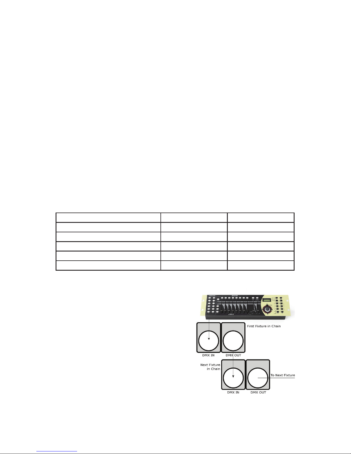
Take It To The Next Level: Set-
ting Up DMX Control
Step 1: Connect the male connector of the
DMX cable to the female connector (output)
on the controller.
Step 2: Connect the female connector of
the DMX cable to the rst xture’s male
connector (input). Note: It doesn’t matter
which xture address is the rst one
connected. We recommend connecting
the xtures in terms of their proximity to
the controller, rather than connecting the
lowest xture number rst, and so on.
Step 3: Connect other xtures in the chain
from output to input as above. Place a
DMX terminator on the output of the nal xture to ensure best communication.
Ready to move on? Well alrighty!
Plug your wireless W-DMX transmitter into the “DMX OUT” of your controller. Please
refer to your transmitting device user manual for further setup instruction.
a. One transceiver with multiple receivers:
1.) Power on all W-DMX receiving xtures, and verify that the signal input in the
xture menus are set to wireless: SET > SIGN > 2.4G.
2.) On the receiving xtures, navigate to SET > WIRE > KEY, and then press
and hold <ENTER> for 3 seconds.
3.) Verify that your W-DMX transmitter is transmitting signal.
4.) The receiving xtures should now be synced.
b. Multiple transceivers, multiple receivers; e.g. 3 groups consisting of a
transceiver & receiver(s) named A, B, and C:
1.) Turn power o of all units.
2.) Group “A” gets powered on, then follow steps above.
3.) Group “B” gets powered on, then follow steps above.
4.) Group “C” gets powered on, then follow steps above.