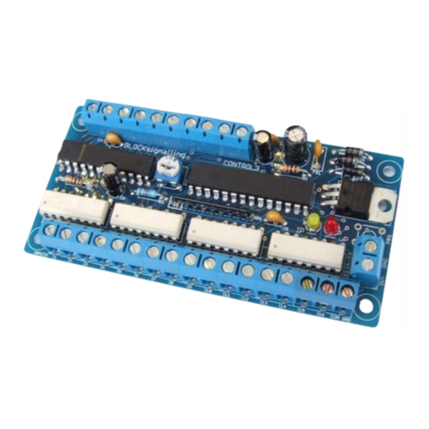
BLOCKsignalling SAS2-BR User manual

DC SHUTTLE WITH STATION STOP
AND ACCELERATION SAS2-BR
The BLOCKsignalling SAS2-BR is a self-contained DC throttle, designed to operate
a single loco along a section of track. Upon reaching the end of the track, the loco
will decelerate to a standstill, wait for a period, then accelerate in reverse. It will run
to the other end of the track and then decelerate to a standstill, wait again, and then
accelerate off forwards.
Runs a DC equipped loco back and forth along a single section of track
Optional station stop function brings the train to rest at a station
Realistic acceleration and deceleration
Quick and easy to connect and set-up
For a long while simple shuttles have been available to model rail enthusiasts to
operate DC locos back and forth along a single section of track. We had wanted to
add further realism by controlling acceleration and deceleration, allowing the option

Page 2 of 19
BLOCKsignalling www.blocksignalling.co.uk
of station stops and so on.
To fill this gap, we have designed the SAS2-BR. This module is a self-contained DC
throttle, designed to operate a single loco along a section of track. Upon reaching
the end of the track, the loco will decelerate to a standstill, wait for a period, then
accelerate in reverse. It will run to the other end of the track and then decelerate to
a standstill, wait again, and then accelerate off forwards.
This action would be appropriate to single line with one train and two terminus
stations.
There is also the option to add one or more intermediate stations. In this case, as
the train enters the vicinity of the station, it automatically slows to a standstill, waits a
set time at the station and then sets off again. There can be any number of such
stations on the single line.
Many programming options are catered for; to control the waiting times, speed, and
randomness of stopping times, etc.

Page 3 of 19
BLOCKsignalling www.blocksignalling.co.uk
Power Supply
The controller is designed for use with a 12V DC plug-top type power supply with a
2.1mm jack connector (centre positive).
Alternatively, the power supply can be connected to the IN1 and IN2 terminals.
If a DC power supply is connected with incorrect polarity no damage will occur, but
the module will not operate.
The module will not be damaged by reverse polarity, being connected to AC rather
than DC, or input voltage up to 35V DC or 25V AC.
Normal traction current is below 0.2A for N gauge and 0.3A for OO and HO gauges
for the speeds shuttle trains are normally operated at.
The module can provide up to 0.5A of traction current, and a power supply with a
minimum output of 0.5A is recommended for Z and N gauges, 1A for OO and HO.
The output is protected against short-circuits.
Do not use the auxiliary terminals on the back of a train controller as the module
may operate unpredictably and could be damaged. These outputs are often
unsuitable as they are designated as a fairly basic power outputs for accessories
such as points motors and may not be smooth or stable.
BLOCK
signalling
Alternative Power Supply Arrangements
(use one only)
REV1
S
REV2
COM
OUT2
OUT1
IN2
IN1
POWER
JACK
12V DC
POWER PACK
+12V
GND
Centre Pin Positive

Page 4 of 19
BLOCKsignalling www.blocksignalling.co.uk
Speed Setting & Waiting Time Adjustment
The locomotive top speed is set by the SPEED adjustment on the module.
Generally the midway position shown in the image below will be a suitable starting
point.
The waiting times are programmed separately for the two ends and the station stop.
These waiting times can only be adjusted by the TIME adjustment on the module if
these individual settings for the waiting time are programmed to a value of 1 (see
later).
Emergency Stop
If you want to stop the train, either in an emergency, or perhaps to re-rail or change a
loco, press the button on the PCB. Track power will be removed and the train will
immediately come to a standstill.
The led on the PCB will flash 0.5seconds on/ 0.5seconds off.
To re-power the train, press and hold the PCB button for 1 second and then release.
BLOCK
signalling
TIME ADJUSTMENT
10mins
MIN
90sec
30sec 6mins
Fine Control Coarse Control
SPEED ADJUSTMENT
100%
MIN
50%
20% 80%

Page 5 of 19
BLOCKsignalling www.blocksignalling.co.uk
Programming Procedure
The module is programmable, and many of the settings can be adjusted to suit.
Programming is performed holding down the Push Button on the module when
switching on the power.
Full details of the programming procedure and options available are given later.
BLOCK
signalling
PUSH-BUTTON
RED LED
POWER
SUPPLY
+
_

Page 6 of 19
BLOCKsignalling www.blocksignalling.co.uk
Connecting the Unit
The track is divided up into a minimum of three sections, the main section and two
ends.
The ends are formed by isolating the right-hand rail by using an insulated rail joiner,
or by cutting the rail with a dremel or hacksaw. Fill any remaining gaps caused by
cutting with epoxy glue to ensure smooth running. This is not necessary at the
testing stage, but will ensure the final running is smooth.
The right-hand rail is relative to the forwards direction of the locomotive.
The length of the end sections of the track should be sized to allow for the loco to
enter, be detected and to stop. Carriages with lights which draw power from the rails
will be detected if they draw more than 4mA.
BLOCK
signalling
Terminal Arrangement
REV1
S
REV2
COM
OUT2
OUT1
IN2
IN1
POWER
JACK

Page 7 of 19
BLOCKsignalling www.blocksignalling.co.uk
If the station stop function is being used, then form isolated sections for each station.
These will need to extend either side of the platform, to allow time for the train to
decelerate.
BLOCK
signalling
STOP –WAIT
REVERSE SPEED1 STOP –WAIT
REVERSE
BLOCKsignalling Shuttle
TRACK BREAK TRACK BREAK
POWER
SUPPLY
+
_
CARE
DO NOT CONNECT TO
TERMINALS ON
CONTROLLER (SEE TEXT)
BLOCK
signalling
STATION
STOP –WAIT
REVERSE CRUISE STATION STOP CRUISE STOP –WAIT
REVERSE
BLOCKsignalling Shuttle
TRACK BREAK TRACK BREAK TRACK BREAK TRACK BREAK
POWER
SUPPLY
_+
CARE
DO NOT CONNECT TO
TERMINALS ON
CONTROLLER (SEE TEXT)

Page 8 of 19
BLOCKsignalling www.blocksignalling.co.uk
Program Flow Diagram
As mentioned above, there are a number of memory locations which can
programmed with different values to change the operation of the module.
Before starting, it is a good idea to write down the memory locations and the values
you are going to set them to.
Programming is performed by holding down the Push Button when switching on the
power. The red led on the PCB flashes at 1 second intervals.
When the required number of flashes is seen for the memory you want to change,
the button is released to select the memory. At this point the led comes on for five
seconds to confirm. Wait until it goes out.
The led then starts flashing again, and this time the button needs to be pressed to
store the value you want the memory to be set to.
After pressing the button, the led flashes 10 times rapidly, and the module starts
operating.
Repeat the process for the any other changes you want to make.
If you make a mistake selecting the memory location or setting the value, you may
want to perform a factory reset to return the module to its default settings.
See the following page for the options available.
Factory Reset
Resetting back to factory settings will allow the module to restart with known settings
and is useful if there may have been a mistake made in programming.
To reset the module back to factory settings, switch off the power to the module and
hold down the Push Button. Apply the power and continue holding the push button
until 1 flash of the led is seen. At this point, release the button. You will see a long
flash of five seconds.
The led will begin flashing again. When you have seen 1 flash, press the button. You
will see a long flash of five seconds and then 10 rapid flashes.
The reset procedure is then complete and the module will restart with factory
settings.
If you make a mistake programming, simply repeat the process.

Page 9 of 19
BLOCKsignalling www.blocksignalling.co.uk

Page 10 of 19
BLOCKsignalling www.blocksignalling.co.uk
Programming Options
East End Waiting Duration (option 3)
Sets the waiting time when the train arrives at the track section connected to the
REV2 terminal.
It a setting of 1 is used, then the waiting time will be set by the TIME adjustment on
the module.
Minimum setting 2 seconds.
Maximum setting 255 seconds.
Default setting (after factory reset) 5 seconds.
After the waiting time, the train departs in reverse.
West End Waiting Duration (option 4)
Sets the waiting time when the train arrives at the track section connected to the
REV1 terminal.
It a setting of 1 is used, then the waiting time will be set by the TIME adjustment on
the module.
Minimum setting 2 seconds.
Maximum setting 255 seconds.
Default setting (after factory reset) 10 seconds.
After the waiting time, the train departs forwards.
Station Stop Duration (option 5)
Sets the waiting time when the train arrives at the track section connected to the S
terminal.
It a setting of 1 is used, then the waiting time will be set by the TIME adjustment on
the module.
Minimum setting 2 seconds.

Page 11 of 19
BLOCKsignalling www.blocksignalling.co.uk
Maximum setting 255 seconds.
Default setting (after factory reset) 5 seconds.
After the waiting time, the train departs in same direction as it arrived.
Speed Control (option 6)
Sets whether the train stops and starts using the acceleration and deceleration
settings, or simply starts and stops with full power immediately applied and removed.
1=starts and stops with full power immediately applied and removed.
2=gradual acceleration and deceleration.
Rate of Acceleration (option 7)
Sets rate of acceleration applied.
Time in seconds for the voltage applied to the track to be raised from OFF up to the
maximum set by the adjuster on the board.
A higher value results in slower acceleration.
Note: the smoothness of the acceleration is highly dependent on the model and the
amount of friction present. Sometimes a longer acceleration time will be required, as
the model will not move during the initial application of voltage to the track.
Minimum setting 1 second.
Maximum setting 20 seconds.
Default setting (after factory reset) 6 seconds.
Rate of Deceleration (option 8)
Sets rate of deceleration applied.
Numerical value is the time in seconds for the voltage applied to the track to be
lowered from the maximum set by the adjuster on the board to OFF.
Minimum setting 1 second.

Page 12 of 19
BLOCKsignalling www.blocksignalling.co.uk
Maximum setting 20seconds.
Default setting (after factory reset) 2 seconds.
East End Delay (option 9)
Sets whether the waiting time when the train arrives at the track section connected to
the REV2 terminal is fixed or randomised.
When randomised, the waiting time varies between 25% and 100% of the set waiting
time.
1=fixed
2=randomised
When set to randomised, the variations in delay will only be obvious for longer
waiting times (greater than 30 seconds or so).
West End Delay (option 10)
Sets whether the waiting time when the train arrives at the track section connected to
the REV1 terminal is fixed or randomised.
When randomised, the waiting time varies between 25% and 100% of the set waiting
time.
1=fixed
2=randomised
When set to randomised, the variations in delay will only be obvious for longer
waiting times (greater than 30 seconds or so).
Station Delay (option 11)
Sets whether the waiting time when the train arrives at the track section connected to
the S terminal is fixed or randomised.
When randomised, the waiting time varies between 25% and 100% of the set waiting
time.

Page 13 of 19
BLOCKsignalling www.blocksignalling.co.uk
1=fixed
2=randomised
When set to randomised, the variations in delay will only be obvious for longer
waiting times (greater than 30 seconds or so).
Maintenance Mode (option 25)
When set to 1, displays the software version of the module by flashing the led on
module to signal a group of four digits.
The power must be removed to reset the module.

Page 14 of 19
BLOCKsignalling www.blocksignalling.co.uk
Step-by-step Connecting Up
There follows a step-by-step approach to connecting up and testing the unit. This
process can also be followed in case of the unit not functioning as expected.
1. Connect power to the module. The supply module is designed for a 12V DC
supply.
2. Switch on the power. The led on the PCB should light for 1 second, then flicker at
about 1/4 brightness.
3. Switch off the power and connect the continuous rail (the one without any breaks)
to the terminal marked OUT1. Connect the other rail to the terminal marked OUT2
and also insert a link between OUT2 and the COM terminal. Place a locomotive on
the track and switch on the power. After a few seconds, the locomotive should move
forwards. If necessary turn the SPEED adjustment on the module clockwise until the
locomotive moves. Switch off the power.
4. If you have a station section, connect it to the terminal marked S. Place a
locomotive on the track so that it will move towards the station section and switch on
the power. After a few seconds, the locomotive should move forwards. When it
reaches the station section, it should come to a stop for a few seconds then move off
again. Switch off the power.
5. Any track after the station should be connected with a link to the track before the
station, to ensure it receives power.
6. The stopping section which causes the train to switch from forwards to reverse
should be connected to terminal REV2. Place a locomotive on the track so that it will
move towards the end section and switch on the power. After a few seconds, the
locomotive should move forwards. When it reaches the end section, it should come
to a stop for a few seconds, then reverse back. Be ready to cut the power in case it
does not stop in time or does not reverse. Switch off the power.
7. Fit the final end section and connect to the REV1 terminal. Repeat the tests in full
to confirm that the train runs as expected backwards and forwards.
8. If you want to adjust any of the settings, this can now be undertaken.

Page 15 of 19
BLOCKsignalling www.blocksignalling.co.uk
Troubleshooting
Q. The locomotive does not move when the module is first switched on.
A. The locomotive should be moving forwards within 10 seconds. If not, increase the
SPEED adjustment on the module clockwise. Gently nudge the loco forwards in
case mechanical or electrical resistance is preventing it moving. If required, test the
locomotive in the same position with your DC controller to check it operates
correctly.
Q. The locomotive runs in the wrong direction when the module is first
switched on.
A. The locomotive motor may be wired incorrectly or the connections between the
module and the track wired incorrectly (reversed).
Q. At the end of the track the locomotive stops briefly, and then continues in
the same direction rather than changing direction.
A. When the train reaches the end of the track connected to the REV2 terminal, it will
stop then reverse. When the train reaches the end of the track connected to REV1,
it will stop then leave the section in the forward direction. Check the connection from
the track ends to the module to check they are correctly wired.
Another common cause of a loco stopping at the end and then continuing in the
forward direction is if the connections to rails have high resistance. Check closely
the connection quality at the attachment to the COMMON rail and to the EAST and
WEST connections.
Q. The train does not stop at a section.
A. The gap in the rail could be blocked by swarf or debris, or the deceleration time
could be set to too long. This is also possible if the REV1 and REV2 ends are
incorrect (reversed).
Another common cause of the locomotive not being slowed by the module is a poor
connection to the rail (poor solder joint or dirty connection).

Page 16 of 19
BLOCKsignalling www.blocksignalling.co.uk
Q. The acceleration is not very smooth.
A. The train has to overcome friction before moving off, after which the friction
reduces. For this reason, more realistic acceleration can be achieved with a longer
acceleration time. This effect is not seen when the locomotive is decelerating.

Page 17 of 19
BLOCKsignalling www.blocksignalling.co.uk
Station Stop on a Loop
The SAS2-BR can be used to provide a Station Stop on a loop.
The locomotive travels forwards around the loop, stopping each time at the station
for a delay period set by the Station Stop Duration memory location.
If you don't want the module to stop trains at the station, you can place a switch
across one of the rail gaps.
When the switch is closed, the module will not detect trains at the station and so the
trains will not be stopped.
PLATFORM
BLOCK
signalling
BLOCKsignalling Shuttle
and Station Stop
TRACK BREAK TRACK BREAK
S
COM +
_
POWER
SUPPLY
_+

Page 18 of 19
BLOCKsignalling www.blocksignalling.co.uk
Use with Reed Switches, Push Buttons, etc
Instead of using the traction current to trigger the SAS2-BR, you can use reed
switches, push buttons, etc.
This could allow the modelling of cable cars, lifts, etc, in addition of conventional
model train shuttles.
See diagram below for wiring.
You may wish to experiment with the positioning of the reed switches, and vary the
acceleration setting, to suit your model.
The motor polarity can be set by trial and error.
If reed switches are used for station stops, a switch can be placed at each end of the
platform, with the switches wired in parallel and connected to the S terminal.
Instead of locating reed switches along the centreline of the rails, it may be possible
to offset them to alter the stopping point for the train depending on direction (fixing
magnets to diagonally opposite corners of the train).
BLOCKsignalling Shuttle
REV1
COM
OUT2
OUT1
IN1
IN2
REV2
BLOCK
signalling
1k Resistor
Reed Switches, etc

Page 19 of 19
BLOCKsignalling www.blocksignalling.co.uk
Funiculars & Cable Cars
Instead of using the traction current to trigger the SAS2-BR, reed switches (as
previously said) can be used, but for funiculars or cable cars it may be difficult to find
a solution to mounting magnets.
Instead, BOD2-RLY infra-red detectors can be used.
Run initially without the cable car fixed to the rope to confirm the correct motor
direction.
It may be necessary to increase the BOD2-RLY sensitivity, or to reduce the
Deceleration rate of the SAS2-BR to ensure the cable car stops at the intended
location.
On a funicular or a cable car with two cars, position the BOD2-RLY modules to
monitor the same car at the top and bottom of the run. Alternately, mount the BOD2-
RLY modules side by side at either the top or bottom of the run.
A centre station can be wired in the same way if required, although if precision is
required for stopping, then two BOD2-RLY modules may be required looking both up
and down the run.
BLOCK
signalling
BLOCKsignalling SAS2-BR
SHUTTLE
POWER
SUPPLY
_+
BLOCKsignalling
BOD2-RLY
BLOCKsignalling
BOD2-RLY
MDRIVE
MOTOR
REV1
REV2
COM
COM NO
COMNO
BOD2-RLY POWER SUPPLY
CONNECTIONS NOT SHOWN
1k RESISTOR
1k RESISTOR
Table of contents
Other BLOCKsignalling Measuring Instrument manuals
Popular Measuring Instrument manuals by other brands

LaserLiner
LaserLiner ClimaHome-Check Plus manual
Kipp & Zonen
Kipp & Zonen LAS MkII ET System instruction manual

ITRON
ITRON Mobile Collector Lite installation guide
Mitutoyo
Mitutoyo LGF-110L-B manual
Kamstrup
Kamstrup ULTRAFLOW 54 DN15-125 Technical description
Extech Instruments
Extech Instruments FM200 user manual
