SCHUNK FMS User instructions
Translation of the original manual
Assembly and Operating Manual
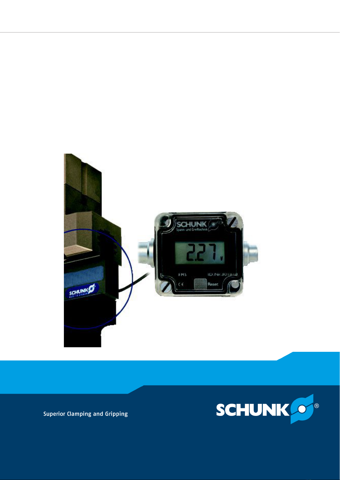
FMS
Force measuring system

Imprint
2
02.00 | FMS | Assembly and Operating Manual | en | 389074
Imprint
Copyright:
This manual is protected by copyright. The author is SCHUNK GmbH & Co. KG. All rights
reserved. Any reproduction, processing, distribution (making available to third parties),
translation or other usage - even excerpts - of the manual is especially prohibited and
requires our written approval.
Technical changes:
We reserve the right to make alterations for the purpose of technical improvement.
Document number: 389074
Version: 02.00|10/07/2019|en
© SCHUNK GmbH & Co. KG
All rights reserved.
Dear Customer,
thank you for trusting our products and our family-owned company, the leading
technology supplier of robots and production machines.
Our team is always available to answer any questions on this product and other solutions.
Ask us questions and challenge us. We will find a solution!
Best regards,
Your SCHUNK team
SCHUNK GmbH & Co. KG
Spann- und Greiftechnik
Bahnhofstr. 106 – 134
D-74348 Lauffen/Neckar
Tel. +49-7133-103-0
Fax +49-7133-103-2399
schunk.com

Table of contents
02.00 | FMS | Assembly and Operating Manual | en | 389074
3
Table of contents
1 General.................................................................................................................... 4
1.1 About this manual ................................................................................................ 4
1.1.1 Presentation of Warning Labels ...............................................................4
1.1.2 Applicable documents ..............................................................................4
1.2 Warranty .............................................................................................................. 5
1.3 Scope of delivery .................................................................................................. 5
2 Basic safety notes ................................................................................................... 6
2.1 Intended use......................................................................................................... 6
2.2 Inappropriate use ................................................................................................. 6
2.3 Constructional changes ........................................................................................ 6
2.4 Spare parts ........................................................................................................... 6
2.5 Environmental and operating conditions ............................................................. 6
2.6 Personnel qualification......................................................................................... 7
2.7 Notes on particular risks....................................................................................... 7
3 Technical data.......................................................................................................... 8
4 Function description and application examples.......................................................10
4.1 Functional description ........................................................................................ 10
4.2 Application example........................................................................................... 12
5 Assembly ................................................................................................................13
5.1 Mechanical installation of the measuring system .............................................. 13
5.2 Electrical installation of the measuring system.................................................. 15
6 Operation ...............................................................................................................16
6.1 Preparing for commissioning.............................................................................. 16
6.2 Determining the conversion factor .................................................................... 16
6.3 Operating the force measuring system .............................................................. 17
7 Troubleshooting .....................................................................................................19
8 Maintenance and care ............................................................................................20

General
4
02.00 | FMS | Assembly and Operating Manual | en | 389074
1 General
1.1 About this manual
This manual contains important information for a safe and
appropriate use of the product.
This manual is an integral part of the product and must be kept
accessible for the personnel at all times.
Before starting work, the personnel must have read and
understood this operating manual. Prerequisite for safe working is
the observance of all safety instructions in this manual.
1.1.1 Presentation of Warning Labels
To make risks clear, the following signal words and symbols are
used for safety notes.
DANGER
Danger for persons!
Non-observance will inevitably cause irreversible injury or death.
WARNING
Dangers for persons!
Non-observance can lead to irreversible injury and even death.
CAUTION
Dangers for persons!
Non-observance can cause minor injuries.
NOTICE
Material damage!
Information about avoiding material damage.
1.1.2 Applicable documents
• General terms of business*
• Catalog data sheet of the purchased product *
• Assembly‐ and Operating Manual of the SCHUNK-module, on
which the sensor is mounted *
The documents marked with an asterisk (*) can be downloaded on
our homepage schunk.com

General
02.00 | FMS | Assembly and Operating Manual | en | 389074
5
1.2 Warranty
If the product is used as intended, the warranty is valid for 24
months from the ex-works delivery date under the following
conditions:
• Observe the applicable documents, Applicable documents [}4]
• Observe the ambient conditions and operating conditions,
Environmental and operating conditions [}6]
1.3 Scope of delivery
The scope of delivery includes
• Force measuring system FMS in the ordered model:
• Electronic processor FMS-A1
• Active force-measuring jaw FMS-ZBA
• Passive intermediate jaw FMS-ZBP
• Cable from the electronic processor to the force/torque sensor
system controller
Depending on the force measuring adapter used, the appropriate
electronic processor must be connected.
FMS Adapter type Electronic processor
50 FMS-A1 301 810
64 FMS-A1 301 810
80 FMS-A1 301 810
100 FMS-A1 301 810
125 FMS-A1 301 810
160 FMS-A2 301 811
200 FMS-A2 301 811
300 FMS-A2 301 811

Basic safety notes
6
02.00 | FMS | Assembly and Operating Manual | en | 389074
2 Basic safety notes
2.1 Intended use
The product is used exclusively to measure gripping forces or to
determine workpiece weights or dimensional deviations.
• The product is intended for installation in a machine/system.
The applicable guidelines must be observed and complied with.
• The product may only be used within the scope of its technical
data, Technical data [}8].
2.2 Inappropriate use
The product is not a safety component in accordance with the EC
Machine Directive 2006/42/EC and must not be used in safety-
relevant parts of machine control units.
2.3 Constructional changes
Implementation of structural changes
By conversions, changes, and reworking, e.g. additional threads,
holes, or safety devices can impair the functioning or safety of the
product or damage it.
• Structural changes should only be made with the written
approval of SCHUNK.
2.4 Spare parts
Use of unauthorized spare parts
Using unauthorized spare parts can endanger personnel and
damage the product or cause it to malfunction.
• Use only original spare parts or spares authorized by SCHUNK.
2.5 Environmental and operating conditions
Required ambient conditions and operating conditions
Incorrect ambient and operating conditions can make the product
unsafe, leading to the risk of serious injuries, considerable material
damage and/or a significant reduction to the product's life span.
• Make sure that the product is used only in the context of its
defined application parameters, Technical data [}8].
• Make sure that the environment is free from splash water and
vapors as well as from abrasion or processing dust. Exceptions
are products that are designed especially for contaminated
environments.
Basic safety notes
02.00 | FMS | Assembly and Operating Manual | en | 389074
7
2.6 Personnel qualification
Inadequate qualifications of the personnel
If the personnel working with the product is not sufficiently
qualified, the result may be serious injuries and significant
property damage.
• All work may only be performed by qualified personnel.
• Before working with the product, the personnel must have read
and understood the complete assembly and operating manual.
• Observe the national safety regulations and rules and general
safety instructions.
The following personal qualifications are necessary for the various
activities related to the product:
Trained electrician Due to their technical training, knowledge and experience, trained
electricians are able to work on electrical systems, recognize and
avoid possible dangers and know the relevant standards and
regulations.
Qualified personnel Due to its technical training, knowledge and experience, qualified
personnel is able to perform the delegated tasks, recognize and
avoid possible dangers and knows the relevant standards and
regulations.
Instructed person Instructed persons were instructed by the operator about the
delegated tasks and possible dangers due to improper behaviour.
Service personnel of
the manufacturer
Due to its technical training, knowledge and experience, service
personnel of the manufacturer is able to perform the delegated
tasks and to recognize and avoid possible dangers.
2.7 Notes on particular risks
DANGER
Danger from electric voltage!
Touching live parts may result in death.
•Switch off the power supply before any assembly, adjustment
or maintenance work and secure against being switched on
again.
•Only qualified electricians may perform electrical installations.
•Check if de-energized, ground it and hot-wire.
•Cover live parts.

Technical data
8
02.00 | FMS | Assembly and Operating Manual | en | 389074
3 Technical data
Electronic processor Designation FMS-A 1/2
Size 50 ... 125 ; 160 ... 380
Operating voltage [V]
Nominal voltage [VDC]
[Rated range]
18 - 30
24
[Reverse polarity protection]
Output signal * [V] -5 ... +5
Current input [mA] < 45
Ambient temperature [°C]
Min.
Max.
-10
+65
Accuracy ** ±3% for ID 301 810
±5% for ID 301 811
Weight [kg] 0.38
IP rating 67 with inserted plug connector
and closed cover
* The output voltage is linear to the forces occurring at the gripper
fingers. The bandwidth of the output signal is not fully used by
each active intermediate jaw.
** Before measuring, a zero adjustment must be carried out.
More technical data is included in the catalog data sheet.
Whichever is the latest version.
The force measuring jaw and the passive intermediate jaw are
always adapted to the gripper:

Technical data
02.00 | FMS | Assembly and Operating Manual | en | 389074
9
Behavior active (with
sensor systems)
Height
H [mm]
Measureme
nt range up
to [N]
Overload
range up to
[N]
Behavior passive
(intermediate jaw)
Height
H [mm]
FMS-ZBA → PGN-plus
50
20 145 290 FMS-ZBP → PGN-plus
50
20
FMS-ZBA → PGN-plus
64 / PZN-plus 64
22 260 520 FMS-ZBP → PGN-plus
64 / PZN-plus 64
22
FMS-ZBA → PGN-plus
80 / PZN-plus 80
24 430 860 FMS-ZBP → PGN-plus
80 / PZN-plus 80
24
FMS-ZBA → PGN-plus
100 / PZN-plus 100
28 685 1370 FMS-ZBP → PGN-plus
100 / PZN-plus 100
28
FMS-ZBA → PGN-plus
125 / PZN-plus 125
30 1120 2240 FMS-ZBP → PGN-plus
125 / PZN-plus 125
30
FMS-ZBA → PGN-plus
160 / PZN-plus 160
36 1600 3200 FMS-ZBP → PGN-plus
160 / PZN-plus 160
36
FMS-ZBA → PGN-plus
200 / PZN-plus 200
40 2325 4650 FMS-ZBP → PGN-plus
200 / PZN-plus 200
40
FMS-ZBA → PGN-plus
240 / PZN-plus 240
46 on request on request FMS-ZBP → PGN-plus
240 / PZN-plus 240
46
FMS-ZBA → PGN-plus
300 / PZN-plus 300
53 5150 10300 FMS-ZBP → PGN-plus
300 / PZN-plus 300
53
FMS-ZBA → PGN-plus
380
64 on request on request FMS-ZBP → PGN-plus
380
64
Range of measurement: range within which the total system has
an accuracy of ±3% / ±5%.
Overload range: range within which the total system has an
accuracy of > ±3% / ±5%. At the end of the overload range, there is
the danger of the mechanical destruction of the intermediate jaw.
Range of measurement and overload range apply to each
intermediate jaw.

Function description and application examples
10
02.00 | FMS | Assembly and Operating Manual | en | 389074
4 Function description and application examples
4.1 Functional description
The FMS force measuring system allows you to measure forces
that act on the base jaw in the direction of the jaw movement. The
force must act centrally on the force measuring adapter.
Depending on the application, one to three active (equipped with
sensor systems) FMS-ZBA intermediate jaws are needed. The
remaining base jaws contain the passive FMS-ZBP intermediate
jaws (without sensor systems). Alternatively, the fingers can be
manufactured accordingly.
For each active intermediate jaw FMS-ZBA, an electronic processor
FMS-A1 is required for the evaluation, as well as a connection cable
FMS-AK for connecting the electronic processor with a power supply
unit and a force/torque sensor system controller (e.g. a PLC).
The active intermediate jaw is made to be deformed specifically in
the micron range. This deformation is detected by an integrated
DMS. Furthermore, the intermediate jaw is made in such a way
that a moment or force from a different direction only slightly
changes the measured value. It is therefore generally only the
gripping forces which are measured.
By means of the force/torque sensor system controller, the DMS
small signal is amplified and output to a voltage level proportional
to the gripping force.
When this is done, a positive value indicates a force acting from
the center of the gripper on the finger (e.g., a workpiece between
the gripper fingers), while a negative value indicates an external
force on the gripper fingers (e.g. reaching into a bore hole).
The output voltage level has a linear relationship to the occurring
force. However, only a change in force will be detected and not an
absolute force.
This means that when measuring, the force/torque sensor system
controller has to be reset to zero before gripping (button on the
force/torque sensor system controller or digital signal). After that,
gripping ought to be started immediately and the output
measured value ought to be evaluated.
To convert the measured value into a force, the factor included in
the data sheet and the value of the base gradient is required.
Since the pitch m is a function of the finger length, the distance
from which the gripping takes place is inserted into the formula
which has been provided by the factory. The distance is the length
between the base jaws of the gripper and the gripping point. The
result of this calculation is the gradient factor for the
corresponding finger length.
Table of contents
Other SCHUNK Measuring Instrument manuals


