Blonder tongue QTPCM-4 User manual

800-523-6049
www.blondertongue.com
©2015 Blonder Tongue Laboratories, Inc. All rights reserved. Specifications are subject to change without notice. Trademarks are the property of their respective owner.
QAM Transcoder Power & Control Module
QTPCM-4
QAM Transcoder Module
QTM-HD-4
QAM Transcoder Module
QTM-HD-4-NPU
Status Date Document No. Issue No. Author
Active August 17, 2015 651227100B 1 KK
Obsolete July 7, 2015 651227100A 1 KK
Stock No.
6238/6243/6223
User Manual

2QTPCM-4
Instruction Manual
We recommend that you write the following information in the spaces provided below.
The information contained herein is subject to change without notice. Revisions may be
issued to advise of such changes and/or additions.
Correspondence regarding this publication should be addressed directly to:
Blonder Tongue Laboratories, Inc.
One Jake Brown Road
Old Bridge, NJ 08857 USA
Document Number: 651227100B
Printed in the United States of America.
All product names, trade names, or corporate names mentioned in this document are
acknowledged to be the proprietary property of the registered owners.
This product incorporates copyright protection technology that is protected by U.S. patents and other
intellectual property rights. Reverse engineering or disassembly is prohibited.
Purchase Location Name:
Purchase Location Telephone Number:
QTPCM-4 Serial Number:

3QTPCM-4
Instruction Manual
Table of Contents
....................................................................................................... 4
.............................................................................................................................. 6
2.1 REVISION HISTORY & REASON ............................................................................................................................... 6
2.2 PRODUCT APPLICATION & DESCRIPTION.............................................................................................................. 6
2.3 PRODUCT SPECIFICATION....................................................................................................................................... 8
................................................................................................................... 9
3.1 UNPACKING ............................................................................................................................................................. 9
3.2 INSTALLATION ......................................................................................................................................................... 9
................................................................................................................................................................ 9
.......................................................................................................
5.1 ACCESSING THE UNIT VIA THE WEB BROWSER .................................................................................................. 11
5.2 MAIN > STATUS SCREEN......................................................................................................................................... 12
5.3 MAIN > INPUT SCREEN........................................................................................................................................... 13
5.4 MAIN > OUTPUT CONFIG....................................................................................................................................... 14
5.5 MAIN > REFRESH TAB ............................................................................................................................................. 16
5.6 NETWORK SCREEN.................................................................................................................................................. 16
5.6.1 ADMIN SCREEN .................................................................................................................................................... 18
5.7 TIME SCREEN........................................................................................................................................................... 20
5.8 EVENT LOG SCREEN................................................................................................................................................ 22
5.9 UPDATE SCREEN...................................................................................................................................................... 23
............................................................................................................... 24
6.1 UPDATING THE SOFTWARE REMOTELY ................................................................................................................ 24

4QTPCM-4
Instruction Manual
Safety Instructions
å Elevated Operating Ambient - If installed in a closed or multi-unit rack assembly, the operating ambient temperature of the rack environment
may be greater than room ambient. Therefore, consideration should be given to installing the equipment in an environment compatible with the
maximum ambient temperature per Section 2.3.
å Reduced Air Flow - Installation of the equipment in a rack should be such that the amount of air flow required for safe operation of the equipment
is not compromised.
å Mechanical Loading - Mounting of the equipment in the rack should be such that a hazardous condition is not achieved due to uneven mechanical loading.
å Circuit Overloading - Consideration should be given to the connection of the equipment to the supply circuit and the effect that overloading of
the circuits might have on overcurrent protection and supply wiring. Appropriate consideration of equipment nameplate ratings should be used
when addressing this concern.
å Reliable Earthing - Reliable earthing of rack-mounted equipment should be maintained. Particular attention should be given to supply connections
other than direct connections to the branch circuit (e.g. use of power strips).
å Read all safety and operating instructions before you operate the unit.
å Retain all safety and operating instructions for future reference.
å Heed all warnings on the unit and in the safety and operating instructions.
close to the point of cable entry as practical.
The STOP sign symbol is intended to alert you to the presence of REQUIRED operating and maintenance
(servicing) instructions that if not followed, may result in product failure or destruction.
The YIELD sign symbol is intended to alert you to the presence of RECOMMENDED operating and maintenance
(servicing) instructions.
The LIGHTNING flash symbol is intended to alert you to the presence of uninsulated "dangerous voltage"
within the product's enclosure that may be of sufficient magnitude to constitute a risk of electrical shock.

QTPCM-4
Instruction Manual
å Follow all installation, operating, and use instructions.
å Unplug the unit from the AC power outlet before cleaning. Use only a damp cloth for cleaning the exterior of the unit.
å Do not use accessories or attachments not recommended by Blonder Tongue, as they may cause hazards, and will void the warranty.
å Do not operate the unit in high-humidity areas, or expose it to water or moisture.
å Do not place the unit on an unstable cart, stand, tripod, bracket, or table. The unit may fall, causing serious personal injury and damage to the
unit. Install the unit only in a mounting rack designed for 19” rack-mounted equipment.
å Do not block or cover slots and openings in the unit. These are provided for ventilation and protection from overheating. Never place the
unit near or over a radiator or heat register. Do not place the unit in an enclosure such as a cabinet without proper ventilation. Do not mount
equipment in the rack space directly above or below the unit.
å Operate the unit using only the type of power source indicated on the marking label. Unplug the unit power cord by gripping the plug, not the cord.
å The unit is equipped with a three-wire ground-type plug. This plug will fit only into a ground-type power outlet. If you are unable to insert the
plug into the outlet, contact an electrician to replace the outlet. Do not defeat the safety purpose of the ground-type plug.
å Route power supply cords so that they are not likely to be walked on or pinched by items placed upon or against them. Pay particular attention
to cords at plugs, convenience receptacles, and the point where they exit from the unit.
å Be sure that the outdoor components of the antenna system are grounded in accordance with local, federal, and National Electrical Code (NEC)
requirements. Pay special attention to NEC Sections 810 and 820. See the example shown in the following diagram:
å We strongly recommend using an outlet that contains surge suppression or ground fault protection. For added protection during a lightning
storm, or when the unit is left unattended and unused for long periods of time, unplug it from the wall outlet and disconnect the lines between
the unit and the antenna. This will prevent damage caused by lightning or power line surges.
å Do not locate the antenna near overhead power lines or other electric light or power circuits, or where it can fall into such power lines or circuits.
When installing the antenna, take extreme care to avoid touching such power lines or circuits, as contact with them can be fatal.
å Do not overload wall outlets or extension cords, as this can result in a risk of fire or electrical shock.
å Never insert objects of any kind into the unit through openings, as the objects may touch dangerous voltage points or short out parts. This could
cause fire or electrical shock.
å Do not attempt to service the unit yourself, as opening or removing covers may expose you to dangerous voltage and will void the warranty. Refer
all servicing to authorized service personnel.
å Unplug the unit from the wall outlet and refer servicing to authorized service personnel whenever the following occurs:
o The power supply cord or plug is damaged;
o Liquid has been spilled, or objects have fallen into the unit;
o The unit has been exposed to rain or water;
o The unit has been dropped or the chassis has been damaged;
o The unit exhibits a distinct change in performance.
å When replacement parts are required, ensure that the service technician uses replacement parts specified by Blonder Tongue. Unauthorized
substitutions may damage the unit or cause electrical shock or fire, and will void the warranty.
å Upon completion of any service or repair to the unit, ask the service technician to perform safety checks to ensure that the unit is in proper
operating condition.
,
Before returning product, please contact the Blonder Tongue Service
Department at 1-800-523-6049, Ext. 4256 or visit our website: for further information.

6QTPCM-4
Instruction Manual
This is the 2nd release of the manual, adding the QTM-HD-4-NPU, updating service features (Section 2.2, below) and
adding note to have all the same input modulation rate on a given QTM-Module (Section 5.3).
QTPCM-4 (QAM Transcoder Power Control Module) provides control and monitoring of QTM-HD-4 (6243), QTM-HD-4-NPU
(6223) and QTM-HD-Plus (6242) transcoder modules via GUI-based web pages. Local or remote control via the Internet is
accomplished with any computer running a standard web browser. The QTPCM-4 will power up to four (4) QTM-HD-4 (2
slot width) or four (4) QTM-HD-4-NPU (2 slot width); eight (8) QTM-HD-Plus (1 slot width); or a combination of modules
all housed in a QTRC (stk# 6233A) rack chassis. The 3RU chassis, when fully loaded with four (4) QTM-HD-4 or (4) QTM-
HD-4-NPU and a QTPCM-4, will transcode sixteen (16) QPSK/8PSK satellite transponders to sixteen (16) QAM channels.
The QTM-HD-4 contains (4) independent transcoders in a single module. Each transcoder accepts one (1) input in QPSK or
8PSK format and delivers (1) QAM channel output, therefore each QTM-HD-4 module transcodes (4) satellite transponders
to (4) QAM channels (54-864 MHz). An integrated satellite selector switch allows the operator to select any of the 4 inputs
to any of the transcoders without the need for an external multi-switch.
The QTM-HD-4-NPU functions the same as the QTM-HD-4, but with a “Null Packet” feature that allows adding/removing
null packets to/from the input stream.
The QTM-HD-Plus features a single transcoder, accepting a QPSK or 8PSK input and delivering a single QAM channel output
in the frequency range of 54-864 MHz. This module is typically used in applications requiring QAM 512/1024 modulation.
It is recommended to disconnect AC power to the QTPCM-4 when installing or removing QTM modules. When replacing
QTM Modules, simply disconnect the input and output cables along with the power supply/control cabling and remove
the module from the chassis. Install a new “like”module and reconnect the cabling. The QTPCM-4 will automatically
configure the new module with the same settings as the replaced module.
If the QTPCM-4 has to be replaced, remove power and all cabling on the rear of the unit. Replace the module and
reconnect power and cabling. Once the new QTPCM-4 has booted up it will read the configuration settings from the
transcoder modules, store them in memory and return to full system operation, without any further user interface.

7QTPCM-4
Instruction Manual
RJ45 connector for 10/100Base-T Ethernet interface for monitoring and configuring the unit.
Only static IP address can be assigned to this interface. The factory default value is 172.16.70.1.
When pushed and held for about 6 seconds, the Status LED will flash momentarily indicating the unit has defaulted to
the original IP address, Usernames and Passwords as shipped from the Factory (shown below).
IP address = 172.16.70.1
Username = Admin (case-sensitive)
Password = pass (case-sensitive)
QTPCM-4 must be power cycled for change to take effect.)
LED is Green = AC power is detected. LED is off = indicates (i) AC power is not connected, or
(ii) AC power is connected but the power supply has failed.
LED is Green = Ready (booted up)
IEC 14 power inlet plug - rated 105 to 240 VAC; 50/60 Hz; equipped with Slo-blo, 4.0 Amps, 250 V Fuse.
Power/Data: Multi-pin connector for module power and control cabling.
: Indicates all transcoders in the module are locked to transponders
:
Output state of one or more transcoders is in OFF or CW Mode.
One or more transcoders are not locked to transponders.
“F” connector for up to four (4) QAM RF outputs 54-864 MHz.
“F” connectors for four (4) QPSK/8PSK satellite RF inputs 950-2150 MHz.
2
3
4
2
3
4
2
3
4
2
3
4

QTPCM-4
Instruction Manual
General
Dimensions (W x D x H)
QTM-HD-4 Module: 3.0 x 10.6 x 5.25 inches (38 x 270 x 134 mm)
Power Dissipation
QTM-HD-4 Module:
21 W
Weight
QTM-HD-4 Module: 1.7 lbs (0.77 kg)
Operating Temperature: 32 to 122 °F (0 to 50 °C)
Storage Temperature: -13 to 158 °F (-25 to 70 °C)
Operating Humidity: 0 to 95% RH @ 35 °C max, non-condensing
Storage Humidity: 0 to 95% RH @ 35 °C max, non-condensing
Alarms/Monitoring/Control
Indicators
QTM-HD-4 Module: Status (Green LED)
Input
Connector: 4x “F” Female
Standards: QPSK & 8PSK (DVB-S, DVB-S2, DCII, LDPC/BCH, & Turbo FEC)
Symbol rate
DVB-S:
DVB-S2:
8PSK Turbo:
Variable; 1 to 45 MSymbols/sec (Mbaud)
Variable; 5 to 33 MSymbols/sec (Mbaud)
Variable; 2 to 30 MSymbols/sec (Mbaud)
Frequency Range: 950 to 2150 MHz
Frequency Granularity: 1 MHz
Bandwidth: Variable, up to 36 MHz
Capture Range: ± 5 MHz
Code Rate
DVB-S:
DVB-S2 (QPSK):
DVB-S2 (8PSK):
Turbo FEC (QPSK):
Turbo FEC (8PSK):
Auto Detect; 1/2, 2/3, 3/4, 5/6, 7/8, DC II
Auto Detect; 1/2, 3/5, 2/3, 3/4, 4/5, 5/6, 8/9, 9/10
Auto Detect; 3/5, 2/3, 3/4, 5/6, 8/9, 9/10
Auto Detect; 1/2, 2/3, 3/4, 5/6, 7/8
Auto Detect; 2/3, 3/4, 5/6, 8/9
Forward Error Correction
(FEC):
DVB / DigiCiper®II
Input Level: -65 to -20 dBm
Impedance: 75 Ω
Return Loss: Greater than 9 dB
Connector:
Modulation:
Standard:
DVB Symbol Rate:
Frequency Range:
Tuning:
Channels’ Bandwidth:
RF Level:
RF Level Adjustment Range:
Frequency Tolerance:
Frequency Stability:
Amplitude Flatness:
Phase Noise:
Spurious:
Broadband Noise:
Impedance:
Carrier Suppression:
Return Loss:
Signal-to-Noise Ratio (SNR):
MER:
I/Q Phase Error:
I/Q Amplitude Imbalance:
1x “F” Female (4x RF QAM channels combined)
QAM 16, 32, 64, 128, and 256
ITU-T J.83; Annex A and B
Variable; up to 7 MSymbol/sec (MBaud)
54 to 864 MHz
CATV Channel Selectable (CH. 2 to 135)
4x 6 MHz in any 42 MHz-wide spectrum
+40 dBmV ±1 dB (100 dBμV ±1 dB)
+32 to +42 dBmV, 1 dB increment
± 0.5 kHz @ 77°F (25° C)
± 5 kHz over 32° to 122° F (0 to 50° C)
± 0.25 dB (over 6 MHz channel)
-95 dBc (@ 10 kHz)
-60 dBc
-70 dBc (@ +40 dBmV output level, 5.5 MHz bandwidth)
75 Ω
45 dB
14 dB typical
Greater than 40 dB typical
Greater than 39 dB typical
Less than 1 degree
Less than 1%
Output
QTM-HD-4 Specifications
General
Dimensions (W x D x H)
QTPCM Module:
QTRC Rack Chassis:
4.5 x 10.6 x 5.25 inches (114 x 270 x 134 mm)
19 x 12.0 x 5.25 inches (483 x 305 x 134 mm)
Power: 105 to 240 VAC; 50/60 Hz
Weight: 5.0 lbs (kg)
Operating Temperature: 32 to 122 °F (0 to 50 °C)
Storage Temperature: -13 to 158 °F (-25 to 70 °C)
Operating Humidity: 0 to 95% RH @ 35 °C max, non-condensing
Storage Humidity: 0 to 95% RH @ 35 °C max, non-condensing
Alarms/Monitoring/Control
Indicators: Power (Green LED)
Status (Green LED)
Remote Monitoring/Control: GUI-based Menu via web browser
QTPCM-4 Specifications
9QTPCM-4
Instruction Manual
You will find the following items in the box:
• QTPCM-4 (QTY=1)
• Power Cord with IEC C13 line socket and 3-pin Type b NEMA 5 plug (QTY=1)
• A hardware bag (item 741018800) containing the following:
Cable wire bracket (QTY=1)
• DC/Control cable harness (QTY=2)
3.2 Installation
The QTPCM-4 AND QTM-HD-4s are designed to be installed in a QTRC chassis (shown below) and a standard 19-inch
(483 mm) rack (EIA 310-D, IEC 60297, and DIN 41494 SC48D).
Connect the Power/Data cables 1- 4 from the QTPCM-4 to the QTM-HD-4 modules. Connect the QTPCM-4 line cord to a
117 VAC, 60 Hz outlet. The “POWER” LED on the front-panel will light green. After approximately 30 seconds, the "Status"
LED will light green, indicating the unit has booted and is ready for operation.

QTPCM-4
Instruction Manual
Local or remote communication with the unit is only possible through a GUI-based menu via any standard web browser.
Before you can communicate with the unit, you must configure your computer’s IP address to be in the same subnet as the
units default IP address. To do so, follow these steps:
(1) Plug one end of the Ethernet cross cable that is provided in the hardware bag to unit’s rear-panel RJ45 interface marked
“Control 10/100”. Plug the other end of the cable to your computer.
(2) The factory default IP address of the unit is 172.16.70.1. To be able to communicate with the unit, you must first change
your computer's IP address.
The following steps explain how to do this for a computer with operating software:
(a) On your computer, open the "Control Panel"
(b) Double-click on "Network Connections"
(c) Right-click on the "Local Area Connection", and then click on the "properties".
(d) A dialog box entitled "Local Area Connection Properties" will appear. In this box, double-click on the "Internet Protocol
(TCP/IP)".
(e) A dialog box entitled "Internet Protocol (TCP/IP) Properties" will appear. Select the "Use the following IP address"
option and enter the following addresses:
No need to enter a value for the Default Gateway.
Click OK to close the dialog box. Now your computer is ready to communicate with the unit.
-OR -
The following steps explain how to do this for a computer with operating software:
(a) On your computer, open the "Control Panel"
(b) Click on “Network and Internet”
(c) Click on the "View network status and tasks"
(d) Click on “Change Adapter Settings” on left hand side of the window
(e) Right-click on the "Local Area Connection", and then click on the "properties".
(f) A dialog box entitled "Local Area Connection Properties" will appear. In this box, double-click on the "Internet Protocol
Version 4 (TCP/IPv4)".
(g) A dialog box entitled "Internet Protocol Version 4 (TCP/IPv4) Properties" will appear. Select the "Use the following IP
address" option and enter the following addresses:
No need to enter a value for the Default Gateway.
Click OK to close the dialog box. Now your computer is ready to communicate with the unit.

QTPCM-4
Instruction Manual
You must complete the steps described in Section 4 before proceeding as follows:
Open a web browser on your computer (Internet Explorer 7 or higher is recommended) and enter the following URL
address . The "Login" Screen (Figure 5.1) will appear.
2. Enter the following case-sensitive factory-default Username and Password, and click on the "Submit" button.
When logged in as Admin, the user has read and write permission. Only one Admin can be logged in
at a time. When logged in as Guest, the user has only read permission. Up to four Guests can be logged in
simultaneously.
Username =(case-sensitive)
Password = pass (case-sensitive)
Username = (case-sensitive)
Password = pass (case-sensitive)
Monitoring and configuration of the unit is achieved via a series of web pages described in following sections. The following
read-only information is displayed in a blue “page header”on top of each web page:
a user-defined field to make identification easier
temperature of unit’s chipset
time elapsed since last time the unit was turned on
a user-defined field to make identification easier
As shown in Figure 5.2, under the blue “page header” the following Primary tabs will appear:
• Primary tab includes the following sub-tabs: Status, Input Config, Output Config, and Refresh.
• Primary tab doesn’t include any sub-tab.
Each Primary and sub-tab is described in the subsequent Sections.

QTPCM-4
Instruction Manual
In the section entitled under the green header, the following parameters about each input program in the TS are
displayed:
1 to 4) selected for it.
L Band center frequency of the transponder
indicates the modulation type of the input program.
SNR of the transponder. The cell will be green when locked and red when not locked to the transponder.
Baud rate of the transponder being received.
In the section entitled under the dark blue header, the following parameters about each output is displayed:
Main transcoder module number (1-4) with transcoder designator (a-d)
QAM RF output channel
= normal QAM RF channel (GREEN Highlight)
= QAM RF channel turned off (RED Highlight)
= CW is a calibrated reference signal that replaces the Normal QAM output. It is used for measuring and
setting the RF output signal level when only analog test instruments are available. Activating the CW mode on any
transcoder (a-d) will affect all others (RED).
The “Main > Status” screen (Figure 5.2) is a “read only” screen and displays Input, and Output information
of the transcoder modules. The screen is automatically refreshed every 30 seconds.
7
2
3
4
6
2 3 4 6
7

QTPCM-4
Instruction Manual
The “Main > Input Config” screen (Figure 5.3a) is a “user-configurable” screen where the L-Band center frequencies, input
source (satellite) and modulation tuning mode parameters can be configured. The QAM output section (blue header) is
displayed as a read-only.
Enter the desired L Band center frequency of the transponder in MHz.
Select the desired satellite input for the transponder being tuned.
Auto box is checked (recommended setting). Unit searches for
the correct Input Modulation format of the transponder to lock on to.
Auto box is not checked. User must select the proper Input
Modulation (Figure 5.3b) and enter in the baud rate of the transponder.
2
3
2 3

QTPCM-4
Instruction Manual
The “Main > Output Config” screen (Figure 5.4a) is a “user-configurable” screen where the output RF QAM channels, levels
and status are set. The Input section (green header) is displayed as a read-only.
Auto mode (recommended setting) searches for the correct output settings to match the input source. When
not in Auto mode (check box unmarked), the user must manually select the proper QAM mode and baud rate for the
input source from a series of drop-down boxes.
If not properly configured the module will not provide the proper output.
This is a read-only field when in Auto Mode. When in Manual mode, the drop down selections are: 64B,
256B, 16A, 32A, 64A, 128A or 256A.
This is a read-only field when in Auto Mode. When in Manual mode, user must enter the QAM
Baud Rate in Mbd/S.
2
3
2 3 4 6

QTPCM-4
Instruction Manual
Select the beginning desired Channel/Frequency on the first transcoder from its pull down menu.
The remaining 3 transcoder sections on each module will display only channels within a 42 MHz bandwidth starting
with the first channel selected. Channel/Frequencies that have already been selected are highlighted in RED to avoid
duplications Channel/Frequency selections should be in increasing (higher) order from the first (top) to
the last (bottom) transcoder within each module and from module 1 to 4.
Pull down level selection. Range is 32 to 42 dBmV in 1 dB increments.
There are 3 available settings, Normal, Off and CW.
= QAM modulated output is present. Changing any output to Normal mode changes all outputs of the
same QTM-HD-4 module to normal mode.
= Output is turned off. (No RF output present) Outputs for each channel can be turned on and off independently.
= Continue Wave (tone) is on, replacing the normal QAM output with a calibrated RF un-modulated signal. CW
mode facilitates user level measurements when only analog test instruments are available. Changing any output
to CW mode changes all outputs on the same QTM-HD-4 module to CW mode.
4
6
2 3 46

QTPCM-4
Instruction Manual
The “Main > Refresh” tab can be clicked while you are on any of the following sub-tab screens: “Status”, “Input Config”,
and “Output Config”. When clicked, it will update all relevant fields/parameters of the active screen as that
information is retrieved from the QTPCM-4 in a real-time basis.
The “Network” screen (Figure 5.6) is a user-configurable screen where the following parameters are configured or displayed:
2
3
4
6
7
9

QTPCM-4
Instruction Manual
indicates the MAC Address of the "10/100 Control" Port
indicates the software version of the QTPCM-4.
Displays the current firmware version.
indicates the current firmware version of Module 1
indicates the current firmware version of Module 2
indicates the current firmware version of Module 3
indicates the current firmware version of Module 4
indicates the current firmware version of Module 5
indicates the current firmware version of Module 6
indicates the current firmware version of Module 7
indicates the current firmware version of Module 8
indicates the unit's serial number
a user-defined field to make identification easier
indicates the period of time before the unit logs itself out if there is no activity on the web
screens. Range is 5, 15, 30, or 60 minutes.
Read-Only field. See section 5.6.1 for details
2
3
7
9
4
6

QTPCM-4
Instruction Manual
This screen allows the user to change/modify the IP network parameters, as well as the Username and Password values
for the unit, user must be logged in to the unit as “Admin” to access the hidden screen shown in Figure 5.6.1. The
"Admin" screen is accessed by typing the URL of the unit followed by a forward slash and Admin.html, for example:
http://172.16.70.1/Admin.html.
2
3
4
6
7
9

QTPCM-4
Instruction Manual
The following parameters can be modified:
unit. The factory default Login is “Admin”. Login is case sensitive.
“pass”. Password is case sensitive and will not be displayed.
used only if the user wants to change the current Administrator’s password. User must enter a new
password (10 characters maximum). Password is case sensitive and will not be displayed.
User must enter the same password as entered in above. If the password entered in &
does not match, an error message will be displayed.
allow any changes. The factory default Guest Login is “Guest”. Login is case sensitive.
“pass”. Password is case sensitive and will not be displayed.
used only if the user wants to change the current Guest password. User must enter a new password
(10 characters maximum). Password is case sensitive and will not be displayed.
User must enter the same password as entered in above. If the password entered in &
does not match, an error message will be displayed.
manual reboot would be required in such case.
The factory default IP address is 172.16.70.1.
is the Subnet Mask address of the unit. It allows the user to access the unit from another network via the
web interface. The factory default Subnet Mask is 255.255.255.0.
monitoring and troubleshooting purposes.
be forwarded for monitoring and troubleshooting purposes. The factory default value, which cannot be modified, is 514.
is the IP address for the Time Server from where the unit can obtain its clock reference (see Section 5.7 for
details).
The factory default value is disabled.
is to enable/disable QTPCM-4 to forward information messages (in blue font) to syslog.
The factory default value is disabled.
2
3
3 3
7
7 7
9
4 4
6

QTPCM-4
Instruction Manual
The "Time" screen (Figures 5.7a and 5.7b) allows the user to set the current date and time for the QTPCM-4. It is
recommended to use the "automatic" option which allows the unit to automatically acquire time settings from a "Time
Server", in which the user must enter the IP address of the time server (see Section 5.6.1 for details). The time server
specified must support the Network Time Protocol (NTP) in order for automatic time acquisition to work properly.
2
3
4
6
6
This manual suits for next models
2
Table of contents
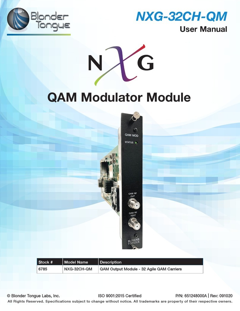
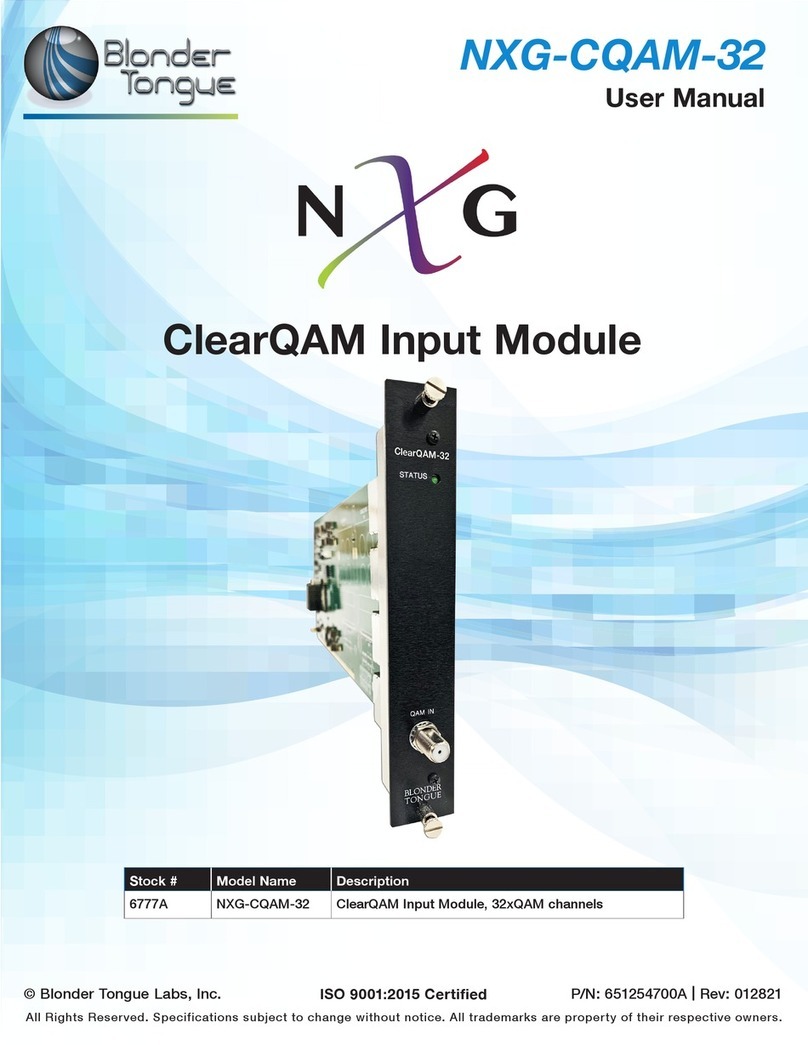
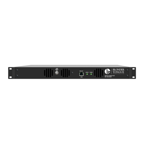
Other Blonder tongue Control Unit manuals

Blonder tongue
Blonder tongue NXG-CQAM-32 User manual

Blonder tongue
Blonder tongue HDE-8C DIN SERIES User manual

Blonder tongue
Blonder tongue NXG-32CH-QM User manual

Blonder tongue
Blonder tongue AQD Series User manual

Blonder tongue
Blonder tongue DAP Series User manual

Blonder tongue
Blonder tongue MDDA-860 User manual

Blonder tongue
Blonder tongue NXG-EPG User manual