Bloomy Battery Simulator 1200 User manual
Battery Simulator 1200
Installation Manual
Bloomy Energy Systems
8700-00001 V1.1

2 Bloomy Energy Systems Battery Simulator 1200 Installation Manual
Copyright Bloomy Energy Systems 2013
Bloomy Energy Systems
257 Simarano Drive
Marlborough, MA 01752
508.281.8288
BES_info@bloomy.com
www.bloomyenergysystems.com
Bloomy Energy Systems provides energy storage test and data acquisition products that enable battery,
grid storage, and automotive companies to improve quality and reduce time to market.
FCC STATEMENT:
This equipment has been tested and found to comply with the limits for a Class A digital device, pursuant
to Part 15 of the FCC Rules. These limits are designed to provide reasonable protection against harmful
interference when the equipment is operated in a commercial environment. This equipment generates,
uses, and can radiate radio frequency energy and, if not installed and used in accordance with the
instruction manual, may cause harmful interference to radio communications. Operation of this equipment
in a residential area is likely to cause harmful interference in which case the user will be required to
correct the interference at his own expense.
NOTE:
Do not open the enclosure. This product contains no user-serviceable parts. Opening the enclosure will
void the warranty.
Battery Simulator 1200 Installation Manual Bloomy Energy Systems 3
Important Information
This symbol identifies messages in this document related to safety.
DANGER
DANGER indicates an imminently hazardous situation, which, if not avoided, will result in death or
serious injury.
Failure to follow the instructions given will result in death or serious injury.
WARNING
WARNING indicates a potentially hazardous situation, which, if not avoided, could result in death or
serious injury.
Failure to follow the instructions given can result in death or serious injury
CAUTION
CAUTION indicates a potentially hazardous situation, which, if not avoided, may result in minor or
moderate injury.
Failure to follow these instructions can result in personal injury.
NOTICE
NOTICE alerts you to practices unrelated to personal injury, such as those that can cause property
damage.
Failure to follow these instructions can result in property damage.
IMPORTANT
IMPORTANT indicates additional information about making effective use of this product.

Battery Simulator 1200 Installation Manual Bloomy Energy Systems 4
Table of Contents
1. Introducing the Battery Simulator 1200.............................................................................. 5
1.1 Features .............................................................................................................................................. 5
1.2 Application Example............................................................................................................................ 7
2. Installation............................................................................................................................ 8
2.1 Wiring Remote Sense ....................................................................................................................... 10
3. Specifications......................................................................................................................11
3.1 Cell Simulation .................................................................................................................................. 11
3.2 Auxiliary I/O Specifications................................................................................................................ 11
3.3 Physical Specifications...................................................................................................................... 12
4. Maintenance ........................................................................................................................13
4.1 Cleaning Instructions......................................................................................................................... 13

Battery Simulator 1200 Installation Manual Bloomy Energy Systems 5
1. Introducing the Battery Simulator 1200
The Battery Simulator 1200 provides a safe and efficient method for battery, grid storage, and automotive
companies to accurately simulate a broad range of battery pack and cell conditions. The Battery
Simulator 1200 provides 12 individually controlled simulated cells and several auxiliary analog and digital
I/O channels. Integrated computing allows the unit to be configured for custom battery profiles and
simulated events. Multiple units can be combined in series to simulate higher channel count battery
packs.
1.1 Features
•Simulate 12 independent cells per unit
•Sink and source 5 VDC and 500 mA per channel
•1000 VDC channel-to-channel and channel-to-ground isolation
•Auxiliary analog and digital I/O
•Ethernet (LAN) and high-speed CAN control communications
•High speed CAN interface compliant with ISO 11898
•NI LabVIEW drivers
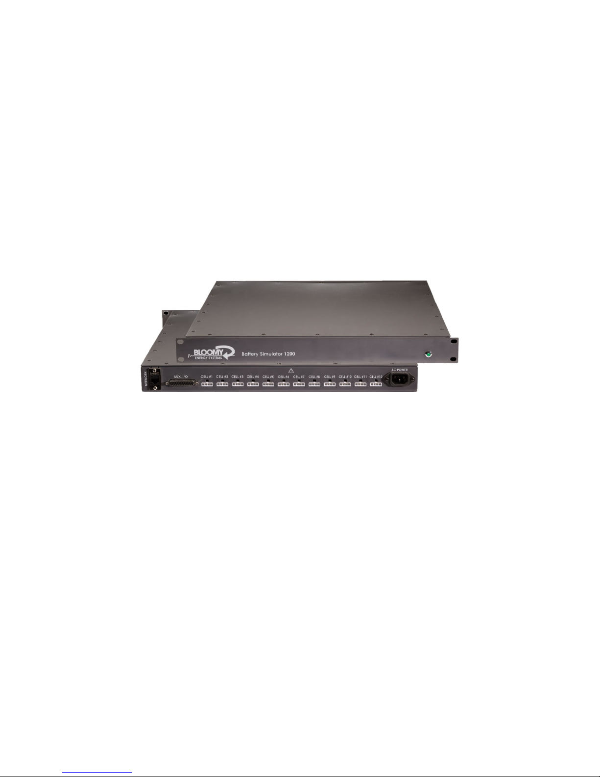
Figure 1: Front View of Battery Simulator 1200 solid running blinking = error state
Power indication:
Power-on Indicator LED Condition
Constant green Operating
Blinking green Error state
Off System off
1. Introducing the Battery Simulator 1200
6 Bloomy Energy Systems Battery Simulator 1200 Installation Manual
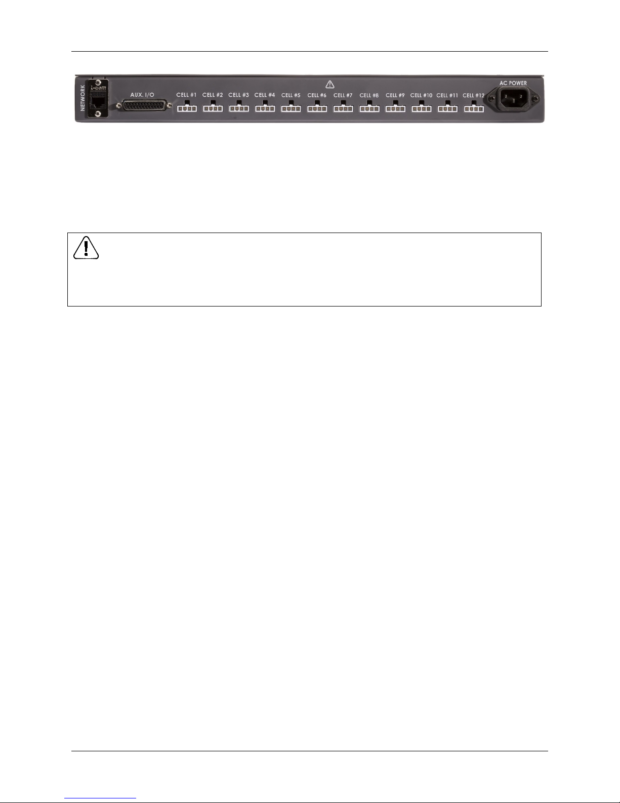
Figure 2: Rear View of Battery Simulator 1200
The outputs of the Battery Simulator 1200 may be connected in series to simulate a pack. This must be
done with extreme caution as hazardous voltages can be generated due to the additive nature of the cell
outputs. For example, 12 cells in series with each cell at 4 volts will generate 48V total.
WARNING
Hazardous voltages can result from connecting outputs in series. Use extreme caution when
connecting outputs in series.
Failure to follow the instructions given can result in death or serious injury

1. Introducing the Battery Simulator 1200
Battery Simulator 1200 Installation Manual Bloomy Energy Systems 7
1.2 Application Example
Highly isolated cells provide the flexibility to integrate the Battery Simulator 1200 into many custom
system architectures. In the example shown below, two units are stacked above a 680V external power
supply to provide an overall pack voltage of 800V.
Typical applications include
•Battery management system testing, verification, and validation
•Battery pack simulation, up to 200 cells
•Hardware-in-the-Loop (HIL) system integration
Battery Simulator 1200 Installation Manual Bloomy Energy Systems 8
2. Installation
To install your Battery Simulator 1200, follow the instructions below.
1. Mount the Battery Simulator 1200 in a 19-in. rack. It uses 1U of space. The cooling air flows from
left to right when viewed from the front of the unit. You can mount additional units above and
below; no space is required between units.
2. Make wiring connections as needed (see Table 1: Connections for Cells 1 –12 and Table 2: Aux
I/O Connections). See also Figure 3: Wiring Remote Sense
3. Connect the AC power cord to the back panel of the unit and to a properly grounded power
receptacle controlled by an input power disconnect device near the equipment and within easy
reach of the operator.
CAUTION
DO NOT open the equipment enclosure. This product contains no user-serviceable components.
Failure to follow these instructions can result in personal injury.
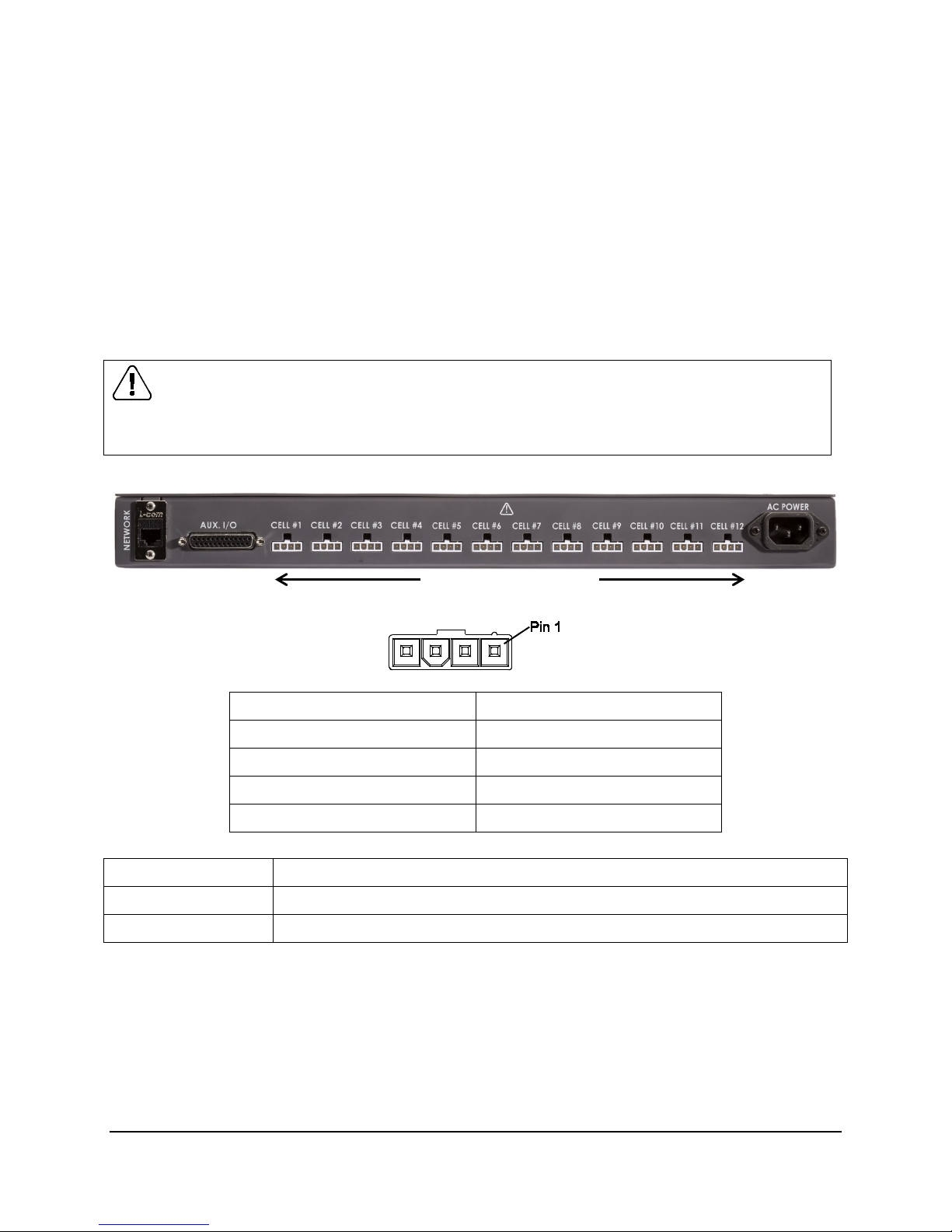
Ethernet Auxiliary I/O Cell Connections (1 – 12) AC Power
Table 1: Connections for Cells 1 –12
Pin number Signal
Pin 1 Sense+
Pin 2 Vout+
Pin 3 Vout–
Pin 4 Sense–
Cell Connection Function
Vout +/– Cell simulator output capable of both sourcing and sinking current
Sense +/– Remote sensing of the Vout +/–signals
NOTE: When connected, the system compensates for voltage drop when current flows through the Vout
+/– cables. The Battery Simulator 1200 contains resistors that connect Vout +/– to Sense +/– to allow
proper sensing at the output connector if the Sense lines are not connected. The system is designed to
compensate for up to 200 mV of total round-trip cable loss.

2. Installation
Battery Simulator 1200 Installation Manual Bloomy Energy Systems 9
Table 2: Aux I/O Connections
Analog I/O Connection Description
Analog Inputs 1 – 8 Single-ended inputs
Capable of measuring 0 to 5 VDC
Analog Output 1 – 2 Can be configured to output voltages of 0 to 5 VDC
CAN+, CAN– Controller area network connections
Digital I/O 1-8 3.3V digital I/Os that can be configured as inputs or outputs capable of
sourcing and sinking up to 3 mA
GND Ground
Pin Number Connection
Pin 1 Analog In #1
Pin 2 Analog In #3
Pin 3 Analog In #5
Pin 4 Analog In #7
Pin 5 GND
Pin 6 Analog Out #1
Pin 7 GND
Pin 8 Digital I/O #2
Pin 9 Digital I/O #4
Pin 10 Digital I/O #6
Pin 11 Digital I/O #8
Pin 12 GND
Pin 13 CAN+
Pin Number Connection
Pin 14 Analog In #2
Pin 15 Analog In #4
Pin 16 Analog In #6
Pin 17 Analog In #8
Pin 18 GND
Pin 19 Analog Out #2
Pin 20 Digital I/O #1
Pin 21 Digital I/O #3
Pin 22 Digital I/O #5
Pin 23 Digital I/O #7
Pin 24 GND
Pin 25 CAN–
IMPORTANT
•Battery Simulator 1200 does not contain a CAN bus termination resistor.
•If needed, add CAN bus termination between the CAN signals at the AUX I/O connector.
•Provide a dedicated CAN network for your Battery Simulator 1200s to avoid addressing conflicts.
2. Installation
10 Bloomy Energy Systems Battery Simulator 1200 Installation Manual
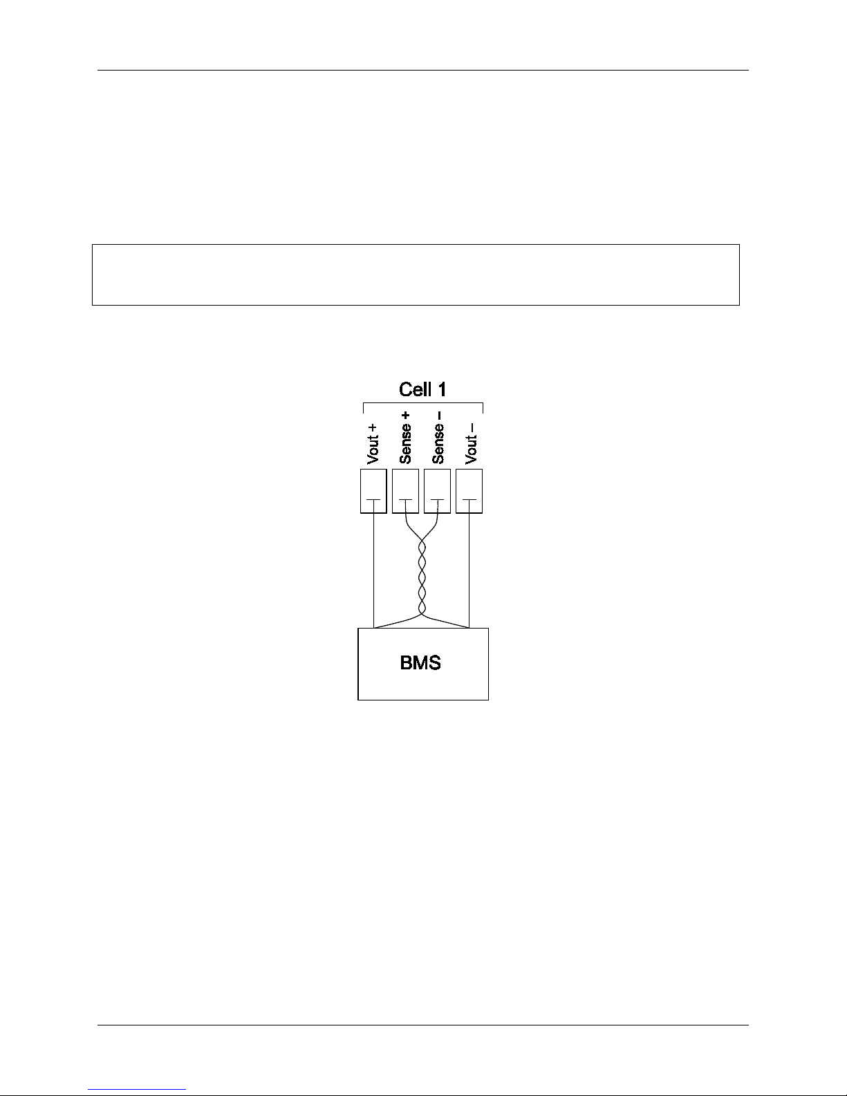
2.1 Wiring Remote Sense
Use remote sensing to regulate the output voltage at the device under test. This feature lets you
compensate for the voltage drop in the leads between the Battery Simulator 1200 and the device under
test.
To set up the remote sensing mode, refer to Figure 3: Wiring Remote Sense and follow these steps:
1. Connect a pair of sense leads from Sense + and Sense – to the device under test.
IMPORTANT
For system stability, use jacketed twisted-pair cables between the remote sense terminals of the unit
and the load.
2. Connect a pair of drive leads from drive Vout + and drive Vout – to the device under test.
Figure 3: Wiring Remote Sense

Battery Simulator 1200 Installation Manual Bloomy Energy Systems 11
3. Specifications
Note: All specifications subject to change.
3.1 Cell Simulation
Sink and Source
Number of Channels 12
Voltage Range 0.0 to 5.0 V
Voltage Resolution 0.1 mV
Voltage Accuracy ±3 mV
Current Range ± 500.0 mA; output derates linearly under 2 V
Current Resolution 0.1 mA
Isolation 1000 VDC CH-TO-CH, CH-TO-GND
Control
Communication LAN (Ethernet)
CAN (optional)
Drivers NI LabVIEW™
Readback
Voltage Resolution .1 mV
Voltage Accuracy ±3 mV
Current Resolution .1 mA
Current Accuracy ±4 mA
3.2 Auxiliary I/O Specifications
Analog Input
Number of Channels 8 (single -ended)
Resolution .1 mV
Max Voltage 5.0 V
Analog Output
Number of Channels 2
Resolution .1 mV
Max Voltage 5.0 V
Digital I/O
Channels 8 (bidirectional)
Logic Level 3.3 V

3. Specifications
12 Bloomy Energy Systems Battery Simulator 1200 Installation Manual
3.3 Physical Specifications
Dimensions 19” W x 1.75” H x 15” D (1U)
(482.6 mm W x 44.5 mm H x 381.0mm D)
Weight 7.5 lb (3.4 kg)
Operating Temperature 0 to 35° C
Input Power Single phase, 100 - 240 VAC/3A, 50/60 Hz
Altitude 9842 ft (3000 m), maximum
Pollution Degree PDX1

Battery Simulator 1200 Installation Manual Bloomy Energy Systems 13
4. Maintenance
4.1 Cleaning Instructions
To clean your Battery Simulator 1200, follow these steps:
1. Power down the unit.
2. Clean with a damp cloth.

Battery Simulator 1200 Installation Manual Bloomy Energy Systems 14
Table of contents


