Benetech GM3125 User manual

EARTH GUARD
LINE
CAT.Ⅲ
600V
High Voltage Insulation Tester
LOCK
PRESS TO TEST
TIMER
SET
5000V
2500V
1000V
500V
AC.V
OFF
0
O
D
I
S
C
T
H
U
A
A
R
G
E
CLEAR
Version: 3125-EN-0
High voltage insulation tester
User's Manual

Preparation before measurement-------------(11)
Voltage measurement----------------------------(12)
Insulation resistance measurement----------(14)
Continuous measurement-----------------------(17)
Timer measurement-------------------------------(18)
Polarization index measurement--------------(20)
The use of green protect-wire------------------(23)
2.Operation Instructions
1. Before use notice
CONTENTS
Check-up--------------------------------- ---(01)
Safety warning-------------------------------------(02)
Feature and function ----------------------------(04)
Specifications ------------------------------------(05)
Diagram of the unit -------------------------------(07)
LCD display --------------------------------------- (09)
--------
3. Other items
Attentions-------------------------------------------(24)
Maintenance and warranty ---------------------(25)

-01- -02-
High Voltage insulation tester----------------1pcs
Red high voltage test wire--------------------------1pcs
Green test wire------------------------------------1pcs
Black test wire------------------------------------1pcs
Alligator clip-------------------------------------- 2pcs
1.5V LR14 alkaline battery-------------------- 8pcs
User's manual------------------------------------ 1pcs
Soft-bag-------------------------------------------- 1pcs
1. Before use notice
Check-up
Carefully unpack your kit and ensure that you have
the following items. In case that any items is missing or
if you find any mismatch or damage, promptly contact
your dealer.
Safety warning
Designed to following safety standards:
IEC 61010-1 CAT. Ⅲ 600V pollution level: 2
CAT. Ⅰ 5000V pollution level: 2
IEC 61010-031 (test wire)
IEC 61326-1 (EMC)
IEC 60529 (Ip40)
Waring:
Electricity is dangerous and can cause injury/ death.
For using the instrument correctly and safely, please
read this manual carefully and follow the instructions.
If you are not quite sure how to proceed, stop and take
advice form qualified person.
This instruction manual contains warning and safety
rules which user be observed by the user.
The symbol " " in this manual have three meanings,
please pay attention to the operation with " " symbol.
Danger--That conditions/operations may cause
serious or fatal injury.
Warning--That conditions/operations can cause
serious or fatal injury.
Caution--That conditions/operations can cause
a injury or instrument damage.
Before testing, make sure to select proper range.
After testing, please turn off the tester.
Caution

-03- -04-
Danger of possible electric shock
Instrument with double or reinforced insulation
DC
AC
Ground terminal
Danger
Do not measure if the voltage is above 600V.
Do not test at flammable / explosive hazard.
Do not measure if the unit or your hand is wet.
Do not go beyond the range of the tester
Do not open the battery door under measuring.
Do not touch any naked lead under measuring
Make sure turn off the unit after measurement.
Warning
The tester must be operated according to this manual
by qualified person who have passed the training.
Do not open the case while testing. If the tester does
not work properly, please return for repair.
Do not replace the batteries in a humidity condition.
Make sure the wire firmly connected to the tester.
Make sure to turn off the power before opening the
battery door.
Check the tester regularly, do not operate if the tester
is not normal(such as lead wire is cracked, the case
broken etc.)
Do not attempt any alterations. Please contacted your
dealer if the tester need to be repaired.
Symbol:
Features and functions
Auto- discharge function to make, the operation safe.
LCD Back-light.
Digital readout display.
Live circuit warning symbols with audio sounds.
Auto- power off function (in 10 minutes without operation)
Timer measurement function.
Low battery indication
PI measurement (Polarization index measurement)
Suitable for 12V DC adapter (12V/1A)

-05- -06-
Specifications:
1. Insulation resistance tester:
2. Voltage tester:
AV
30~600V(50/60Hz)
30~600V (Resolution 1V)
DV
±30~±600V
1V
±2%rdg±3dgt
Measuring
range
Resolution
Accuracy
Rated
voltage
Test
range
Open
circuit
voltage
Rated
current
Short- circuit
current
Accuracy
500V
0.0~99.9MΩ
100~999MΩ
DC 500V
+30%, -0%
0.5MΩloading
1mA~1.2mA
1000V
0.0~99.9 MΩ
100~999 MΩ
1.00~1.99GΩ
DC 1000V
+20% -0%
2500V
0.0~99.9 MΩ
100~999 MΩ
1.00~1.99GΩ
10.0~99.9GΩ
DC 2500V
+20% -0%
5000V
0.0~99.9 MΩ
100~999 MΩ
1.00~9.99GΩ
10.0~99.9GΩ
100~1000GΩ
DC 5000V
+20% -0%
1MΩ loading
1mA~1.2mA
2.5MΩ loading
1mA~1.2mA
5MΩ loading
1mA~1.2mA
Approx. 1.3mA
±5%rdg±3dgt (0~99.9GΩ)
±20%rdg±3dgt (above 100GΩ)
3.Technology parameter:
Technology parameter Technology index
Display Max. 999 counts LCD display
(1000 counts only at 1T is displayed)
Over range indication
OL mark appears on insulation
resistance range.
LO mark appears on voltage's range.
Auto- ranging
Range shifts to upper range: 1000 count
Range shifts to lower range: 95 counts
(merely on the insulation resistance range)
Sample rate 0.5~ 10 times/sec
Operable altitude
Temperature 0~40C, humidity <= 85%
Temperature -20~ 60C, humidity <= 90%
Operation circumstance
Storage circumstance
Overload protection
Voltage resistance
Less than 2000m (Indoor use)
AC8320 (50/60Hz)/ 5 second (between
electrical circuit and enclosure)
Insulation resistance 1000M of more/ DC 1000V (between
electrical circuit and enclosure)
Power supply DC12V (8x1.5V LR14 battery)
Battery's life Approx. 15 hours
Dimension 153x 96 mmx 200
Weight 1032g (without batteries and test wires)
Insulation resistance : AC 1200V/ 10s
Voltage : AC 720V/ 10 s

-07- -08-
EARTH GUARD
LINE
CAT.Ⅲ
600V
High Voltage Insula tion Tes ter
LOCK
PRESS TO TES T
TIMER
SET
5000V
2500V
1000V
500V
AC.V
OFF
0
O
D
I
S
C
T
H
U
A
A
R
G
E
CLEAR
DC 12V
1
2
3
4
7
11 12 13
89
6
5
10
TIMER
SET
CLEAR
Diagram of the unit 1.LCD display.
2. :Time set button.
3 :.Backlight button
4.Test button.
5.Function switch.
6. :Time choose button.
7.Red high voltage test wire socket.
8.Green protect test wire socket.
9.Black test wire socket.
10.DC input interface (12V/1A)
11.Black test wire and alligator clip.
12.Green protective test wire and alligator clip.
13.Red Hi- volt test wire.
Caution
The data in the diagram of the unit is a simple instruction.
Read the operation to get a detail operation guidance.
2
1
3
45789
10
11
12
16 15 14 13
6
-09- -10-
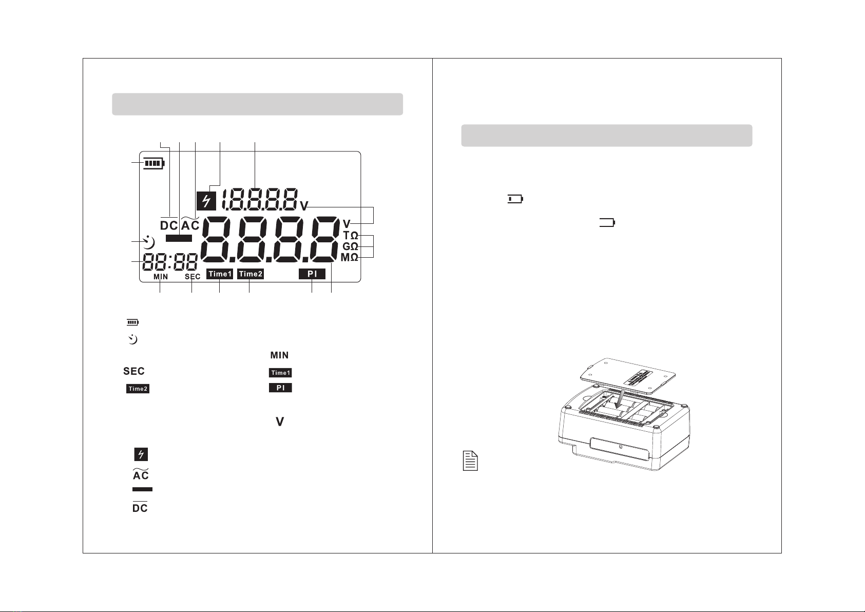
1. : Battery symbol;
2. :Time count down symbol;
3.Timing display ; 4. :Minute;
5. :Second; 6. :Timers 1;
7. :Timers 2; 8. :Polarization index
9.Voltage/ insulation resistance reading.
10.Resistance unit 11. :The voltage unit
12.Voltage display section
13. :High voltage warning .
14. :Alternating current .
15. :Minus symbol.
16. :Direct current .
LCD Display
2.Operation instructions
1. Check the battery voltage & battery replacement:
a.Set the function switch to any position other than OFF.
b. When the battery mark shown at the upper left on the LCD
is “ ”, the battery is almost exhausted. Replace the
batteries to proceed to measurement.
When battery mark is “ ”, the battery voltage is bel-
ow the lower limit of the operating voltage. The accuracy
cannot be guaranteed.
c.Battery replacement:
1>. Take down all the test line after you turn off the
instrument.
2>. Uninstall four screws at the bottom and open the
battery door.
3>. Replace all old batteries with new batteries. Please
note the polarity.
4>. Cover the battery door and fasten the screws. As the
picture below:
Preparation before measurement
Caution:
Remove the batteries if the tester is not required for an
extended periods in order to avoid damage to the battery
compartment and erosion resulting from a battery leakage.

-12--11-
High Voltage Insulation Tester
LOCK
PRESS TO TEST
TIMER
SET
5000V
2500V
1000V
500V
AC.V
OFF
0
O
D
I
S
C
T
H
U
A
A
R
G
E
CLEAR
EARTH GUA RD
LINE
CAT.Ⅲ
600 V
LINE
High Voltage Insulation Tester
LOCK
PRESS TO TEST
TIMER
SET
5000V
2500V
1000V
500V
AC.V
OFF
0
O
D
I
S
C
T
H
U
A
A
R
G
E
CLEAR
EARTH GUA RD
LINE
CAT.Ⅲ
600 V
LINE
2. Connecting test wires:
Insert the test wire firmly to the connector terminal on the
instrument;
Connect the red test wire to “Line”socket;
Connect the black tests wire to “Earth” socket;
Connect the green guard wire to “Guard” socket;
The connect method like the picture below:
black
test wire
red
test wire
green
protect wire
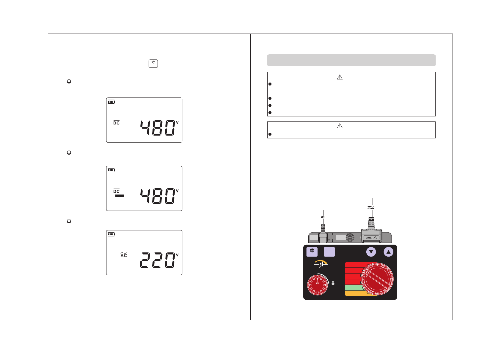
1.Connect the red test lead and black test lead to reciprocal
terminal socket.
2.Set the function switch
to "AC. V" position, like
the picture below: Don't
press "Test" button, this
instrument with DC/AC
self-detection and DC
voltage +/- identification
function.
black
test wire
red
test wire
Voltage measurement(30~600V)
Danger
Do not take measurement on a circuit above AC/ DC 600V
The user maybe hazard when testing installation that has a
large current capacity, do not touch any bare wire at this
time.
Do not take measurement if the battery cover removed.
DANGER
Caution
Make sure that there is no electrical charge exists on the circuit
under test.
Make sure to put on a pair of insulated gloves for high voltage.
Do not take measurement when thunder rumbling.
Do not take measurement if the battery cover removed.
Do not take measurement when the live circuit waring is active.
-13- -14-
CLEAR
LINE
CAT.Ⅲ
600V
EARTH GUARD
LOCK
PRESS TO TEST
TIMER
SET
5000V
2500V
1000V
500V
AC.V
OFF
0
O
D
I
S
C
T
H
U
A
A
R
G
E
CLEAR
3. Connect the red or black test pin to the pole, if the beam
is dim you can press the “ ” button to turn on back
light. The LCD display shown as below:
Connect the red pin which test direct voltage to +,
connect the black to -, LCD display as below:
Connect the red pin which test direct voltage to-, connect
the black to +, LCD display as blow:
LCD display as blow when test AC:
4. Remove the test pin after measurement.
Then set the function switch to OFF position.
red
test wire
black
test wire
Insulation resistance measurement
1. Connect the red test wire and black test wire to reciprocal
terminal socket.
2. Setting the function switch to proper position according
to the content of insulation material, (you can take a try
follow the sequence 500V/ 1000V/ 2500V/5000V if you
do not know the resistance range) for example, 2500V:

-15- -16-
3. Connect the test pin/clip to the unit tested, Press the test
button to measure, the buzzer will sound continuously and
the high voltage light will be actived. LCD display as below:
4. Release the button, the instrument will discharge the high
voltage automatically, and the high voltage light and the
sound of the high voltage will stop.Only remove the test
wires when LCD display oV. LCD display the
tested time and insulation resistance as below:
After a full screen display, LCD display as below:
V
High voltage
Indicator
(LINE)一
CURRENT
RX
EARTH(+)
5. Remove the terminal pins/alligator to the part under test
then turn off the unit.
6. The test principle of the insulation resistance:
Resistance value can be obtained by applying a certain
high voltage to trigger following current R=V/I.
Do not touch the circuit under test immediately after
testing. Capacitance stored in the circuit may cause
electric shock.
Danger
Caution:
1. It consumes 25mA current when the function switch is at any
position other than OFF (Auto- power - off: Approx 1uA). Set the
function switch to OFF position when. Not use the instrument.
2. The test switch of this instrument have two test methods:
a. Instant measurement: press the TEST button only, it produces
high voltage to test insulation resistance. Release the button,
the measurement will stop.
b. Continuous measurement: press the TEST button and rotate
to lock the switch to take measure continuously.
Turn the TEST button to anti-clockwise and release it, the
tester will stop the measurement.
3. To make sure safety of measurement and the instrument.
Choose 500V lever when the insulation resistance is less than
50mΩ.

TIMER
SET
-17- -18-
3. Remove the test wires firstly, then set the function switch
to OFF position.
Continuous measurement
1. About the first and second procedure, please refer to
INSULATION RESISTANCE MEASUREMENT.
2. Connect the test pin/clip to the unit tested. Press and
Rotate the PRESS TO TEST button clockwise to perform
a continuous measurement. The buzzer will sound at this
time. LCD display as below:
After measurement, rotate the test button original position in
anticlockwise, The instrument will discharge the high voltage
automatically, the high voltage light and sounds will stop.
Remove the test wires only when LCD display 0V, LCD
display as below:
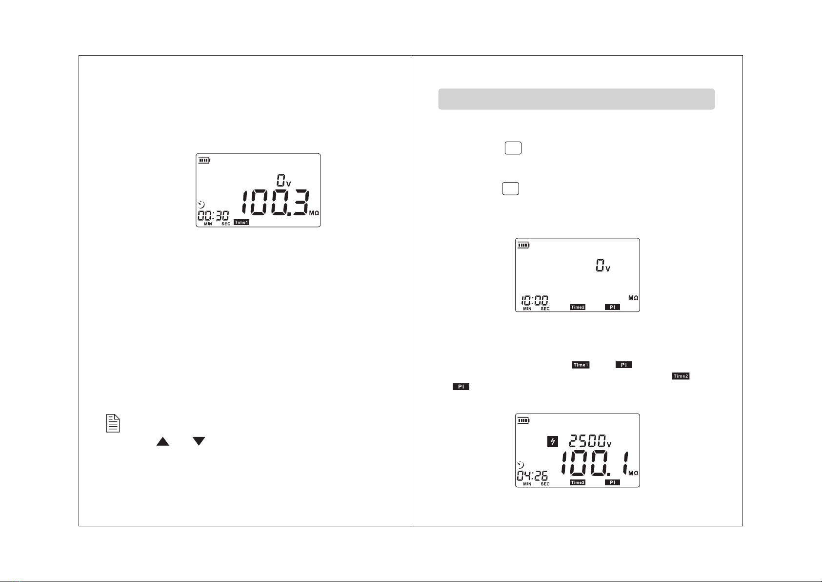
Timer measurement
This is a function to conduct a test automatically at any
set time.
1.
2. Press the “ ” button and TIME1 mark will be
displayed.
3. Press or button to set up times, for example,
30 second. LCD display as below:
About the first and second procedure, please refer to
INSULATION RESISTANCE MEASUREMENT.
4.Press and rotate the PRESS TO TEST button clockwise
to perform a timer measurement of insulation resistance,
the buzzer will sound and the “ ” will flash, LCD
display as below:
TIMER
SET
TIMER
SET
-19- -20-
5. Measurement automatically stop when the time exausted
at the set time, The high voltage light turns off and the
sound of the high voltage stop. Rotate test button back to
the original position in anticlockwise. LCD display as
below:
Caution:
Press or button, time can be set at every 5sec
form 00:00 to 01:00, after that rang time can be set at
every 30sec.
Polarization index measurement
1.
2.Press the “ ” button, TIME1 mark will displayed,
and then press ▼ or ▲ button to set time,
for example: 1 min;
Press the “ ” button and TIME2 mark will
displayed, then press ▼ or ▲ button to set time,
for example: 10 min.
LCD will display like the followed picture:
About the first and second procedure, please refer to
INSULATION RESISTANCE MEASUREMENT.
4.Connect the test nip/clip to the insulation material under
test. Press and turn clockwise the test button clockwise.
The buzzer will sound, the and will flash when
measure insulation resistance at“Time1”, the and
will flash when measure insulation resistance at
“Time2”, LCD display as below:

TIMER
SET
TIMER
SET
TIMER
SET
-21- -22-
5. When the measurement is completed at TIME2, the high
voltage light get off and the sound of the high voltage stop.
Turn test button back to the original position anticlockwise,
the rate (insulation resistance of TIME2/ insulation resista-
nce of TIME1 )display as below:
6. Press the “ ”button at the first time: LCD display the
insulation resistance value of TIME1 like the followed
picture:
Press the “ ” button at the second time: LCD will
display the insulation resistance value of TIME2 like the
followed picture:
Polarization
index 4 or more
Criteria Very good Good Dubiouts Unsatisfactory
4- 2.0 2.0- 1.0 1.0 or les
Caution
The data shown in the operation instruction are merely
a example to illustrate, please refer to the value obtained
in your practice.
Polarization index= Resistance value in 10 min (TIME2)
Resistance value in 1 min (TIME1)
7.Polarization index measurements usually set TIME 1 to
1 min. set TIME2 to10min.
Press the “ ”button at the third time, LCD will display
the Polarization index value.

LINE
CAT.Ⅲ
600V
EARTH GUARD
-23- -24-
The use of green protect- wire
Connect the green protect- wire to GUARD terminal. It
is only used to measure the insulation resistance of cable.
Nip the shield like during the measurement to reduce the
effect of leakage current (please reference before test
instruction to understand other operation).
Connect the wires as below:
Black
Test line
Red
Test line
Green
protect line
LINE
GUARD
EARTH
(ISULATION RESISTANCE METER)
POWER
SUPPLY
INDICATOR
LEAK CURRENT
CORE WIRE
ISOLATION
MATERIAL
PROTECTIVE
WIRE
ISOLATION
SCARF SKIN
Other items
1. The screen is vacant after turn on the instrument:
Check whether the battery is installed correctly. Open
the battery door, check the symbol + - on the battery
must accord with symbol on the battery compartment.
2. If the battery voltage lower than 8.5v +- 0.2v and the LCD
displays low battery indication, please replace the battery
to avoid the in-correct reading.
Please read the page 10 of operation instruction for the
battery replacement operation.
3. The connect way of test pin with alligator clip is like the
following picture:
4. Remove the battery form the instrument if it is not required
for extended period of time in order to avoid damage to
the battery compartment and the electrode resulting from
a battery leakage.
Attentions:

-25-
Maintenance and warranty
Maintenance:
1. Do not store or use the unit in following locations where
the unit may be subject to:
a. Splashes of water or high levels of dust.
b. air with high salt or sulphur content.
c. Air with other gases or chemical materials.
o
d. High temperature or humidity (above 60 C, 90%,) or
direct sunlight.
2. Do not disassemble the unit or attempt internal
alterations.
3. Never use alcohol or thinner to clean the unit casing that
will especially erode the LCD surface; just clean the unit
lightly as needed with little clean water.
Warranty:
1. About relative warranties please read warranty card.
2. We disclaim any liability due to: client's transportation
damages; incorrect use or operation;
manipulation, alterations or repair attempts.
Statement
a. We reserve the rights of upgrading and amending
the design of the product as well as the manual
updating, and the product is subject to change
without any further notification.
b. Dispose of battery should be in accordance with
local laws and regulations.
Table of contents
Other Benetech Test Equipment manuals


