
7
Contents
Introduction ..................................................2
Features ...................................................2
Included accessories .......................................2
Safety information ............................................3
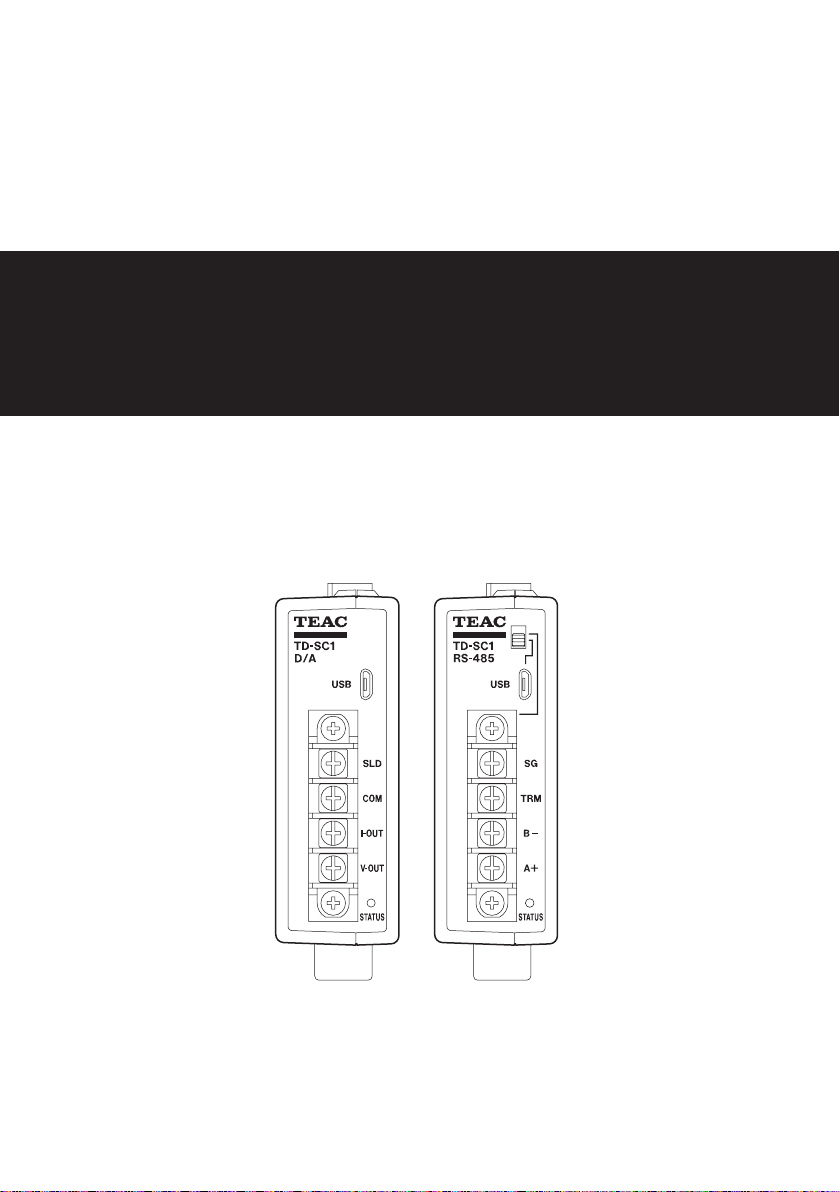
1. Names and functions of parts...............................9
1-1. Front...................................................9
1-2.Top .................................................. 10
1-3. Bottom .............................................. 10
2. Installation ............................................... 11
2-1. Attaching to a DIN rail................................ 11
2-2. Removing from a DIN rail............................. 11
3. Making connections ...................................... 12
3-1. Connecting to the input/output connector .......... 12
3-1-1. Input/output connector ........................ 12
3-2. Connecting a strain gauge transducer................ 12
3-2-1. About the remote sense function............... 12
3-2-2.Notes about bridge voltage (excitation voltage)...12
3-3. Control input and output terminals .................. 14
3-3-1. Control input terminals......................... 14
3-3-2. Connecting control input terminals............. 14
3-3-3. Comparison output terminals .................. 15
3-4. Connecting the DC power supply input terminals .... 15
4. Control app .............................................. 16
4-1. App availability ...................................... 16
5. USB ...................................................... 17
5-1. Connections ......................................... 17
5-1-1. USB port ....................................... 17
5-1-2.When using a TD-SC1 (485) ..................... 17
5-2. Commands .......................................... 17
6. RS-485.................................................... 18
6-1. RS-485 overview ..................................... 18
6-2. Connections ......................................... 18
6-2-1. RS-485 terminals ............................... 18
6-2-2. Inserting and removing RS-485 terminal bank .. 18
6-2-3. Connecting the RS-485 terminals ............... 18
6-2-4. Selecting RS-485 transmission .................. 18
6-3. RS-485 transmission settings ......................... 19
6-4.Transmission protocols (TD Format/TD Format (BCC)). 20
6-4-1. Commands..................................... 20
6-4-2. Responses...................................... 21
6-5.Transmission commands ............................. 22
6-5-1. Polling (0001)................................... 22
6-5-2. Status Polling (0002)............................ 23
6-5-3. Indicator Value Polling (0003) ................... 24
6-5-4.Setting value writing/execution command format ..24
6-5-5. Setting value loading command format ........ 25
6-5-6.TEDS command format......................... 25
6-5-7. Continuous transmission format................ 26
6-5-8. Real-time value/hold value format .............. 26
Status .......................................... 26
6-6. Commands .......................................... 27
6-6-1. Execution ...................................... 27
6-6-2. Polling ......................................... 27
6-6-3. Calibration ..................................... 27
6-6-4. Condition settings.............................. 28
6-6-5. Comparison settings ........................... 29
6-6-6. Hold function settings.......................... 30
6-6-7. System settings ................................ 30
6-6-8.TEDS ........................................... 32
7. D/A converter ............................................ 33
7-1. D/A output terminals ................................ 33
7-2. D/A Zero............................................. 33
7-3. D/A Full Scale ........................................ 34
7-4. D/A Output Mode ................................... 34
7-5. D/A Maximum Voltage ............................... 34
8. Calibration. . . . . . . . . . . . . . . . . . . . . . . . . . . . . . . . . . . . . . . . . . . . . . . . 35
8-1. Procedures shared by all calibration methods ........ 36
8-1-1. Locking and unlocking calibration values ....... 36
8-1-2. Remote Sense .................................. 36
8-2. Equivalent input calibration .......................... 37
8-2-1. Bridge Voltage.................................. 37
8-2-2. Decimal Point Position.......................... 37
8-2-3. Rated Output Value............................. 37
8-2-4. Rated Capacity Value ........................... 37
8-2-5. Zero Balancing ................................. 37
8-2-6. D/A Output Mode .............................. 38
8-2-7. D/A Maximum Voltage ......................... 38
8-2-8. Calibration Value Lock .......................... 38
8-3. Actual load calibration ............................... 38
8-3-1. Bridge Voltage.................................. 39
8-3-2. Decimal Point Position.......................... 39
8-3-3. Zero Balancing ................................. 39
8-3-4. Rated Capacity Value (load calibration).......... 39
8-3-5. D/A Output Mode .............................. 39
8-3-6. D/A Maximum Voltage ......................... 39
8-3-7. D/A Full Scale .................................. 39
8-3-8. Maximum Display Value ........................ 39
8-3-9. Calibration Value Lock .......................... 39


-G3 User manual")


