Sage 925VST User manual

SAGE INSTRUMENTS
925VST VoP Service Tester
USER’S MANUAL
Version 1.2
VoP Service Tester
MOS = 4.50
F1 F2
SAGE 925VST
7
PRS
4
GHI
1
QZ
*
+
8
TUV
5
JKL
2
ABC
0
9
WXY
6
MNO
3
DEF
#
-
CLR BACK NEXT
INFO
F1 F2
TALK
ON/
OFF
Volume

OVERVIEW ................................................................................................................................................. 4
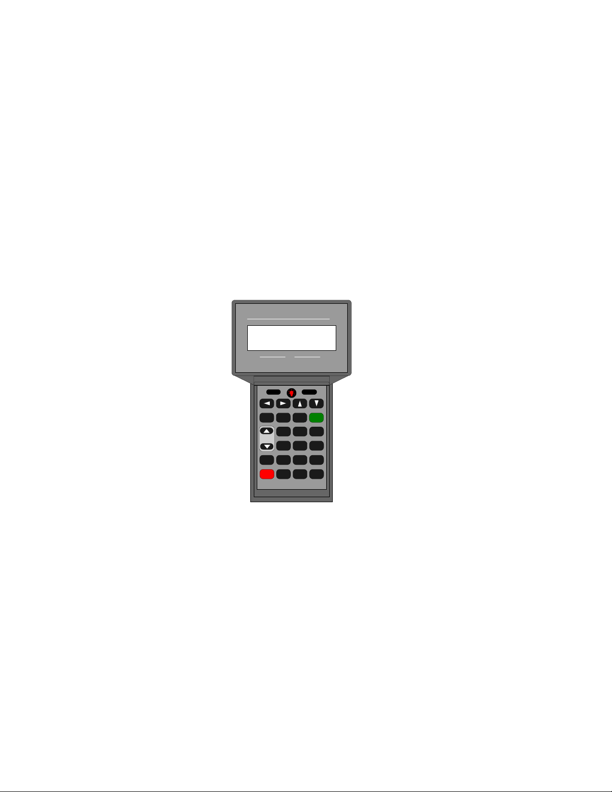
THE SAGE 925VST ..................................................................................................................................... 4
VOP TEST SYSTEM (VTS)...........................................................................................................................4
VTS FEATURES ........................................................................................................................................... 5
General Features..................................................................................................................................... 5
Other Tests ............................................................................................................................................. 6
THE 925VST TEST ENVIRONMENT ............................................................................................................. 7
GETTING STARTED.................................................................................................................................. 9
UNPACKING................................................................................................................................................. 9
CHARGING THE BATTERIES ......................................................................................................................... 9
Initial Charge.......................................................................................................................................... 9
Recharging............................................................................................................................................ 10
UNDERSTANDING THE INTERFACE............................................................................................................. 10
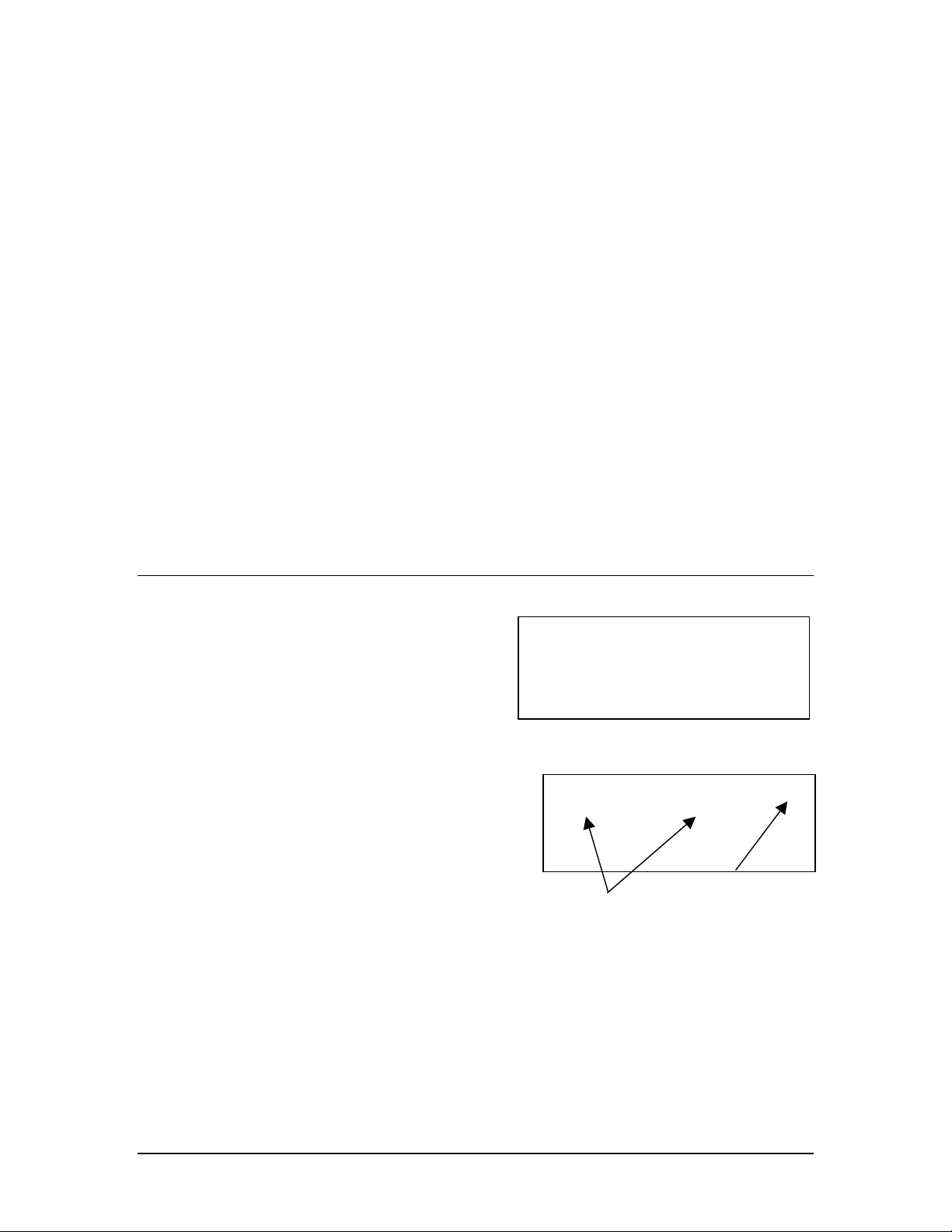
Display Characters................................................................................................................................ 10
Arrows ............................................................................................................................................................... 10
Blinking Cursor ................................................................................................................................................. 10
< Bracketed Selection >..................................................................................................................................... 10
Keypad.................................................................................................................................................. 11
F1 and F2........................................................................................................................................................... 11
Light Bulb Key .................................................................................................................................................. 11
Backspace and Forward..................................................................................................................................... 11
Up, Down, and Escape....................................................................................................................................... 11
CLR (Clear) ....................................................................................................................................................... 11
INFO.................................................................................................................................................................. 12
BACK ................................................................................................................................................................ 12
NEXT ................................................................................................................................................................ 12
Volume Control ................................................................................................................................................. 12
TALK ................................................................................................................................................................ 12
ON/OFF............................................................................................................................................................. 12
Telephone Keys ................................................................................................................................................. 13
Alphabetic and Numeric Data Entry.............................................................................................................. 13
SETTING UP THE BASIC OPERATING FEATURES ........................................................................................ 14
Interfaces .............................................................................................................................................. 14
Test Interface ..................................................................................................................................................... 14
Serial Port .......................................................................................................................................................... 15
Environment ......................................................................................................................................... 15
Template ............................................................................................................................................................ 15
Tx Level Point ................................................................................................................................................... 15
Testline Timeout................................................................................................................................................ 16
SMOS Testline TPT .......................................................................................................................................... 16
No Answer Timeout .......................................................................................................................................... 16
Max Wait Dial-Tone.......................................................................................................................................... 16
Audible Alert ..................................................................................................................................................... 16
Backlight Timeout ............................................................................................................................................. 16
Display Contrast ................................................................................................................................................ 17
Phone Lists ........................................................................................................................................... 17
Responder Mode................................................................................................................................... 18
SMOS Responder .............................................................................................................................................. 18
PVIT Send ......................................................................................................................................................... 18
Echo Generator .................................................................................................................................................. 19
Setting Level and Delay ................................................................................................................................ 19
Disabling Echoes........................................................................................................................................... 19
Minimum On and Off Requirements............................................................................................................. 20
925INSTALL TOOL..................................................................................................................................... 20
User Configuration ............................................................................................................................... 20
Phone List.......................................................................................................................................................... 21
Environment ...................................................................................................................................................... 21

Test Setup .......................................................................................................................................................... 22
Action ................................................................................................................................................................ 23
Upgrading the 925VST Application Software...................................................................................... 24
TEST TEMPLATES ...................................................................................................................................... 24
Call Progress and DVM........................................................................................................................ 26
SMOS ................................................................................................................................................... 26
DTMF Callback.................................................................................................................................... 27
Echo Sounder ....................................................................................................................................... 27
100 Responder...................................................................................................................................... 28
102 Responder...................................................................................................................................... 28
PVIT Measure ...................................................................................................................................... 29
Help ...................................................................................................................................................... 29
USING THE 925VST ................................................................................................................................. 30
FIELD TESTING PREREQUISITES................................................................................................................. 30
CONNECTING TO THE LINE UNDER TEST ................................................................................................... 30
RJ Connections..................................................................................................................................... 30
Ground Connection .............................................................................................................................. 30
RUNNING TESTS ........................................................................................................................................ 31
Aborting a Test..................................................................................................................................... 32
VIEWING TEST RESULTS ........................................................................................................................... 32
Test Result Types ................................................................................................................................. 33
SMOS Director.................................................................................................................................................. 33
Echo Sounder..................................................................................................................................................... 34
PVIT Measure.................................................................................................................................................... 34
FAXTX.............................................................................................................................................................. 35
DTMF Callback................................................................................................................................................. 36
100 Director....................................................................................................................................................... 36
102 Director....................................................................................................................................................... 36
DVM.................................................................................................................................................................. 37
Call Progress...................................................................................................................................................... 37
Test Info............................................................................................................................................................. 37
EXPORTING RESULTS ................................................................................................................................37
REMOTE CONTROL OF THE 925VST.......................................................................................................... 38
Setting Up............................................................................................................................................. 38
User Level Commands ......................................................................................................................... 38
Interface............................................................................................................................................................. 39
Set Default Test Line Type................................................................................................................................ 39
Set Test Line Duration....................................................................................................................................... 39
Set SMOS Test Line Parameters........................................................................................................................ 40
Set PVIT Test Line Parameters.......................................................................................................................... 40
Set EGEN Test Line Parameters........................................................................................................................ 40
Test Line Start ................................................................................................................................................... 40
Test Line Stop.................................................................................................................................................... 41
Test Level Commands.......................................................................................................................... 41
Initialize............................................................................................................................................................. 41
Go ...................................................................................................................................................................... 41
Setup.................................................................................................................................................................. 42
Exit .................................................................................................................................................................... 42
Print ................................................................................................................................................................... 42
Exit .................................................................................................................................................................... 42
USING THE 925VST AS A TELEPHONE....................................................................................................... 42

© 2004 SAGE INSTRUMENTS 9100-0925-01 V1.2 4
Overview
The Sage 925VST
The Sage 925VST is the field component of the Sage Voice over Packet Test System
(VTS). The 925VST initiates VoP service qualification and maintenance tests from a
customer premise or any 2-wire or 4-wire access point to a Sage responder that is typically
located in the central office. The Sage responder performs the cooperative farend
responder test functions and sends the measurement data back to the 925VST for review,
processing (pass/fail), and storage. The 925VST is designed to be portable and durable
and can function just like a telephone handset.
The 925VST initiates tests and displays results immediately upon completion. Once a test
is selected on the 925VST, it runs automatically. Test criteria templates installed on the
925VST determine whether a test passes or fails.
The 925VST comes equipped with the Sage Next Generation VoP Test suite. Including
SMOS, Packet Voice Impairment Test (PVIT), Echo Sounder, DVM, DTMF, and
Callback tests. In addition, the 925VST supports legacy 100 and 102 test line
measurements. Additional options include
• 2-wire analog interface
• 4-wire analog interface
• responder mode
• fax text
VoP Test System (VTS)
The 925VST and farend responder are designed to qualify VoP service installations and
support on-site field maintenance. Tests are useful to confirm proper lAD (Integrated
Access Device) installation, softswitch DN translation, end-to-end voice quality, and
detect and isolate echo, packet impairments, and poor network performance.
VoP Test System has two components:
• The Sage 925VST hand-held unit used in the field
• A Sage farend responder that can be located at any telephony 2-wire, 4-wire, or T1/E1
termination point.

© 2004 SAGE INSTRUMENTS 9100-0925-01 V1.2 5
VTS Features
The Sage VoP Test System can:
• Test End-to-End Voice Quality (QoS)
ο Mean Opinion Score (MOS)
ο Comfort Noise Level
ο Audio Level
• Troubleshoot and Isolate Echo Impairments
ο Detect up to 4 echoes
ο Echo Level
ο Echo Delay
• Troubleshoot and Isolate Packet Impairments
ο Voice Frame Slips & Duration
ο Voice Frame Loss & Duration
ο Voice Clips & Duration
ο Latency (delay)
ο Noise Hits
• Verify Fax & Standard Legacy Test Lines
ο Fax Grp3 Verification
ο Telcordia 100 and 102 Test Line Directors
General Features
General FeaturesGeneral Features
General Features
• Codec Type Detection
• DTMF Digit Verification
• Built-in Butt Set
• Call Completion Time
• Automatic Callback
• Dial tone Delay, Loop Current
• Ring Voltage and Frequency Verification
• On-Hook Voltage and Loop Current
• Includes RS232 Interface for Data Export and
• Software Upgrades

© 2004 SAGE INSTRUMENTS 9100-0925-01 V1.2 6
Other Tests
Other TestsOther Tests
Other Tests
The 925VST may come equipped with other tests that do not require a Sage farend
responder or that enable the 925VST to emulate a farend responder. They provide
detailed results that can be viewed only on the 925VST. These tests may include:
• 100 Responder Noise Measurement
The 100 responder noise measurement operates with a type 100 quiet termination test
line.
• 102 Responder Loss Measurement
The 102 responder loss test operates with the type 100 milliwatt test line.
• Fax Emulator Test
The Fax emulator test operates with a standard facsimile machine
• SMOS Test Line
• Packet Voice Impairment Test (PVIT) Send Test Line
• Echo Generator Test Line

© 2004 SAGE INSTRUMENTS 9100-0925-01 V1.2 7
The 925VST Test Environment
Use the Sage 925VST hand-held unit in the field to connect to the voice line being tested.
The interface can be at a customer premises or at any 2-wire or 4-wire access point. The
925VST can connect to customers served by:
• copper loop
• hybrid fiber coax loop
• wireless loop
• IP
• digital PBX
Using menus on the 925VST, the technician selects the test and then initiates a call to the
Sage farend responder (either the Sage 94xRTS, 950RTS, 935AT, 930i, 925VST, or
325EV). The selected test runs automatically. The 925VST retains pass/fail parameters for
IP-PBX
Softswitch
Local
IAD
MOS = 4.25 Pass
F1 F2
SAGE 925VST
7
PRS
4
GHI
1
QZ
*
+
8
TUV
5
JKL
2
ABC
0
9
WXY
6
MNO
3
DEF
#
-
CLR BACK NEXTINFO
F1 F2
TALK
ON/
OFF
Volume
94xRTS/950RTS
935AT/930i
Class V
Class IV
ISPs
Managed
IP Network
Trunking
Gateway
Enterprise Offloading
925VST

© 2004 SAGE INSTRUMENTS 9100-0925-01 V1.2 8
each test. At the conclusion of the test, the 925VST displays an immediate result and
pass/fail notification if pass/fail template is enabled.
Using menus on the 925VST, the technician can view stored detailed results of each
portion of the test. During the test, the technician can listen to the dial tone, progress tones,
and other audible sounds. Typically, a test takes less than 30 seconds to complete.

© 2004 SAGE INSTRUMENTS 9100-0925-01 V1.2 9
Calibrating
Please wait . . .
Battery: ••••••••••••
Getting Started
Unpacking
The following items should arrive with your 925VST:
• 925VST hand-held unit
• 925VST CD-ROM
• AC adapter/power cord
• Test interface connector cable (RJ-48 plug on one end; RJ-11 and RJ-22 plugs on the
other end)
• Banana plug to alligator clip ground cable
• Field Test Quick Guide
Additional items may be included with your shipment:
• RJ-48 to alligator clips cable/adapter
• RS-232 cable
• Padded case with belt loop
Charging the Batteries
WARNING: Use only the AC/DC transformer supplied with the 925VST to charge the
batteries. Other transformers may damage the 925VST and void the warranty.
Initial Charge
Initial ChargeInitial Charge
Initial Charge
The 925VST comes with rechargeable batteries
installed at the factory. Before using the
925VST for the first time, charge the batteries
for two hours.
Do not turn on the 925VST while the batteries
charge for the first time.
1. Make sure the 925VST is off (i.e., the display is blank and dark).
2. Plug the AC adapter power cord into the appropriate AC outlet.
3. Plug the cord from the AC adapter into the power port on the bottom of the
925VST. Leave the power cord plugged in for at least two hours to allow the
batteries to fully charge.

© 2004 SAGE INSTRUMENTS 9100-0925-01 V1.2 10
Sage Instruments
925VST 2.2000
Self Test Passed
Hit Next to Continue
Recharging
RechargingRecharging
Recharging
Each time the 925VST is turned on, the system checks the batteries. To fully recharge the
battery:
1. Turn off the 925VST.
2. Plug the AC adapter into the appropriate AC outlet.
3. Plug the cord from the AC adapter into the power connector on the 925VST.
4. Allow the 925VST to charge for two hours.
NOTE: You can use the 925VST while it is connected to the AC adapter unless it is being
charged for the very first time.
To ensure that the battery is fully charged:
1. Turn off the 925VST.
2. Disconnect the AC adapter from the 925VST.
3. Turn on the 925VST and note the indicator bars during the booting process.
Indicator bars reach across the full display when the batteries are fully charged.
Understanding the Interface
The 925VST screen displays alphabetic and numeric (alpha-numeric) information on four
rows, 20 characters wide. Navigate the screens
and menu selections using the keypad.
At any time, press the INFO key to display
help text or directions.
Display Characters
Display CharactersDisplay Characters
Display Characters
ARROWS
An ½or ¾arrow in the upper right corner
of the display indicates that additional
selections or data are available on other
screens. The number next to the arrow
indicates which screen is currently
displayed. Use the Sor Tkey as indicated
in the display to see more selections.
BLINKING CURSOR
The blinking cursor indicates an active field waiting for data entry from the keypad.
< BRACKETED SELECTION >
Brackets indicate the active selection or field. An option enclosed in angle brackets is the
default or last option that was chosen. Bracketed options appear in numbered lists and as
F1 and F2 function key selections.
Test Select 1 ¾
1:<SMOS Director>
2:DTMF Callback
3:Echo Sounder
brackets indicate
“last” selected item
press T
TT
Tfor more
selections

© 2004 SAGE INSTRUMENTS 9100-0925-01 V1.2 11
In numbered lists with multiple screens, the bracketed option might not appear on the
currently displayed screen. Use the Sor Tkeys to locate the bracketed option.
To select the bracketed option, press the NEXT key. The NEXT key advances to the next
screen based on the bracketed option, even when the bracketed option is not on the current
screen.
Keypad
KeypadKeypad
Keypad
F1 AND F2
Use the F1 and F2 function keys for various data entry tasks. For
example, F1 and F2 toggle between numeric and alphabetic data
entry. In some cases, screen text describes the functions of the F1
and F2 keys. Brackets (< >) indicate the active selection.
LIGHT BULB KEY
Use the light bulb key to control the display light. While the unit is
on, press the key to toggle the light on or off. The light
automatically turns off after a few seconds. You can define the
number of seconds the light remains on using the Backlight Timeout option on the Setup
menu. (See Backlight Timeout on page 16.)
W
WW
WX
XX
XBACKSPACE AND FORWARD
Press the Wkey to delete the character to the left of the cursor.
Press the Xkey to enter a blank space (screen displays as a dash) and move the cursor to
the right. A blank space in a telephone number represents a 1-second pause in the dialing
sequence.
S
SS
ST
TT
TUP
, DOWN, AND ESCAPE
Use the Sand Tkeys to scroll through a list that span several screens or to move to the
previous or next screen. You can use the Sand Tkeys whenever an up or down arrow
(½or ¾) appears in the upper right corner of the screen display.
On the first screen of a list, only the ¾arrow appears in the display. In the last screen of a
list, only the ½arrow appears in the display. However, you can press the Sand Tkeys
on any screen. If you are on the last screen and you press the Tkey, the display moves to
the first screen. If you are on the first screen and you press the Skey, the display moves
to the last screen.
You can also use the Sand Tkeys to escape from a data entry field without saving your
changes. If you enter data and then press the Sand Tkeys, the field reverts to the last
saved entry.
CLR (CLEAR)
Use the CLR key to erase the current data in a data entry field. Press and hold the CLR
key to display the Main Menu. Use the CLR key to delete results when reviewing results.
(Note: The 925VST will ask for confirmation before deletion.)

© 2004 SAGE INSTRUMENTS 9100-0925-01 V1.2 12
INFO
Press the INFO key to display help for the current screen.
BACK
Press the BACK key to move back one screen or level. Repeatedly pressing the BACK
key eventually displays the Main Menu.
NEXT
Press the NEXT key to move to the next screen or operation. From a data entry screen,
press the NEXT key to accept the current selection or field contents and move to the next
data entry screen or function. You can also use the NEXT key to abort a test in progress.
See Aborting a Test on page 32.
VOLUME CONTROL
During tests, you can hear the sounds produced (e.g., dial tone, call progress tones, etc.).
Use the volume control keys to adjust the volume of these sounds. To adjust a sound,
press and hold the key while the sound is audible. Release the key when you reach the
desired level.
TALK
Use the TALK key when you use the 925VST as a telephone or butt-set. (A speaker and
microphone are located on the back side of the unit.)
When you press the TALK key, the 925VST goes off hook and the keyboard functions as
a telephone keypad. Press the TALK key again to toggle back to on-hook and disable the
telephone speaker and microphone.
ON/OFF
Press the ON/OFF key to turn on the 925VST. To turn off the 925VST, press and hold the
ON/OFF key until the display darkens. The 925VST will turn itself off after 10 minutes if
(1) the AC adapter is not plugged in, (2) no test is in progress, (3) there is has been no key
press for 10 minutes, and (4) the unit is not in talk mode. The 925VST will power itself on
when a call comes in.

© 2004 SAGE INSTRUMENTS 9100-0925-01 V1.2 13
telephone keypad
TELEPHONE KEYS
The 925VST telephone keypad performs many functions and
can be used for both alphabetic and numeric (alpha-numeric)
data entry. Use the keypad for:
• making menu selections
• entering telephone numbers
• entering other information (e.g., your identification
number, names for responder phone lists, selecting display
options)
Alphabetic and Numeric Data Entry
Some data entry fields accept both alphabetic and numeric
characters. While the cursor is in a field that accepts both types
of characters, use the F1 and F2 function keys to toggle the keypad between alphabetic
entry and numeric entry.
There are two ways to enter alpha- numeric characters in a
field:
1. Toggle between alphabetic and numeric entry
modes by pressing F1 and F2.
- or -
2. Leave the keypad in alphabetic mode, and press
the key repeatedly until the desired letter or
number is displayed.
For example, when the keypad is in alphabetic mode, the 2 key provides four characters:
A, B, C, and 2. The first time you press the 2 key, an “A” displays at the cursor position.
Press the 2 key again (within one second) to display a “B;” press the 2 key a third time to
display “C.” Press the 2 key a fourth time to display a “2.” The next press will start the
cycle over again by displaying an “A.”
Press the Wto backspace. Press the Xkey enter a dash (-) in a phone number. The dash
represents a one-second delay. If you enter a character and the next character is entered by
the same key, wait for the cursor to automatically advance to the next character space, or
press the Xkey.
1s
t
press
2n
d
p
ress
3r
d
press
4
th
press

© 2004 SAGE INSTRUMENTS 9100-0925-01 V1.2 14
1:<Interfaces>
2:Environment
3:Phone Lists
4:Responder Mode
Interfaces
1:<Test Interface>
2:Serial Port
Select Interface 1¾
1:<2W Loop 600>
2:2W Loop 900
3:2W Gnd-Start 600
Select Interface 2¾
1:Gnd-Start 900
2:4 Wire Dry
Setting Up the Basic Operating Features
Basic operating features include selecting the type of line used, enabling audible alerts,
and brightening or darkening the display screen. You can use the Setup screens (listed
below) to change the basic operating features of the 925VST.
• Interfaces (line types and ports)
• Environment (light and sound levels)
• Phone lists (responder phone numbers)
• Responder Mode (type of responder emulated
by the 925VST)
You can also use the 925Install Tool software to setup the environment and phone lists.
This software allows you to set up the environment options and phone lists in an
application on your computer, then transmit the information via an RS-232 cable to the
925VST. See 925Install Tool on page 20 for more information.
Interfaces
InterfacesInterfaces
Interfaces
Use the Interfaces screens to select the type of line
to be tested (i.e., the customer’s line), designate the
responder mode for the 925VST, and set up the
925VST’s serial port.
To access the Interfaces screens, from the Main
Menu press the 2 key to display the Setup menu, then press 1.
TEST INTERFACE
Use the Test Interface screen to set the line type interface for the phone line being tested.
• 2-wire loop 600 — specifies a 2-wire interface,
loop-start signaling, and a terminating
impedance of 600 ohms
• 2-wire loop 900 — specifies a 2-wire interface,
loop-start signaling, and a terminating
impedance of 900 ohms
• 2-wire ground start 600 — specifies a 2-wire
interface, ground-start signaling, and a
terminating impedance of 600 ohms
• 2-wire ground start 900 — specifies a 2-wire
interface, ground-start signaling, and a terminating impedance of 900 ohms
• 4-wire dry — specifies a 4-wire interface with no on-/off-hook signaling.

© 2004 SAGE INSTRUMENTS 9100-0925-01 V1.2 15
SERIAL PORT
Use the Serial Port screen to set the parameters for the 925VST serial port connection.
Choose the baud rate (1200, 9600, 38400, or 115200 bps), data bits (8 or 7), and parity
(none, even or odd). For best results, use the default settings:
• 38400 bps (this is the baud rate)
• 8 data bits
• No parity
Use the optional 925VST serial port (RS-232) cable (Part #: 9400-0048-01) to connect the
925VST to your computer.
NOTE: In previous versions, users had to manually place the 925VST in Download Mode.
This is now done automatically; you do not need to change the mode of the 925VST to
download software.
• For more information on setting up the 925VST using the 925Install application on
your computer, see 925Install Tool on page 20.
• For more information on upgrading the 925VST application software, see 925Install
Tool on page 20.
• For more information on downloading new test templates to the 925VST from the
925VST Template UI application on your computer, see Test Templates on page 24.
• For more information on exporting test results to your computer, see Exporting
Results on page 37.
• For more information on controlling the 925VST remotely from your computer, see
Remote Control of the 925VST on page 38.
Environment
EnvironmentEnvironment
Environment
To access the Environment screens, from the Main Menu press the 2 key to display the
Setup menu, then press 2 again.
There are nine Environment screens that allow you to adjust various settings. The screens
are listed below in the order in which they appear.
TEMPLATE
A template is a set of threshold criteria that determines whether a test passes or fails. At
the Template screen, press 1 to enable or 2 to disable templates. The default is Disabled.
Templates can be enabled only if a valid template has been installed. For more
information on creating and download templates, see Test Templates on page 24.
TX LEVEL POINT
When interfacing to equipment that is exceptionally sensitive to input signals from the
925VST, you can adjust (increase or decrease) the level of test signals transmitted by the
925VST. For example, setting the TX Level Point to -10 dB reduces the transmitted signal
level to 10 dB below the normal transmit level. The allowable range is –50dB to 0dB; the
default TX Level Point is 0dB.

© 2004 SAGE INSTRUMENTS 9100-0925-01 V1.2 16
TESTLINE TIMEOUT
When operating in a continuous test director mode you must manually stop Echo Sounder
and PVIT Send. See Remote Control of the 925VST on page 38 for more information.
For PVIT Measure in both test director mode and responder mode, PVIT Send in
responder mode, and Echo Generator (responder mode) you can use this setting to specify
how long the 925VST will run a test. When the maximum run-time has expired, the test
display switches to the results display. At the Testline Timeout screen, enter the number of
seconds before the 925VST automatically ends a test. The maximum run-time for
continuous mode director tests is 999 seconds; the default is 300 seconds.
SMOS TESTLINE TPT
If the network under test is exceptionally slow in establishing and end-to-end talk path
between the director and responder units, you can adjust the duration of the test progress
tone (answer tone; TPT) transmitted by the 925VST when it is in the SMOS Responder
mode. TPT is transmitted by the SMOS Responder function in response to a “call” from
the far end SMOS Director function. The duration can be from 1 to 99 seconds; the default
is 10 seconds.
NO ANSWER TIMEOUT
While the 925VST dials the responder to begin a test, the display reads Calling Test
Line, Please wait… You can specify how long the 925VST will wait for an
outgoing call to be answered. If the responder does not answer the call, the test is aborted
and the display reads Test Aborted. At the No Answer Timeout screen, enter the
number of seconds the 925VST waits for an outgoing call to be answered. The maximum
wait allowed is 99 seconds; the default is 40 seconds.
MAX WAIT DIAL-TONE
When the 925VST is connected to the line under test and the desired responder phone
number is selected, the 925VST listens for a dial tone before dialing the responder. The
925VST dials the responder number even if no dial tone is detected. At the Max Wait
Dial-Tone screen, enter the desired number of seconds the 925VST will wait for a dial
tone before dialing the responder. The maximum wait allowed is 99 seconds; the default is
10 seconds.
AUDIBLE ALERT
Audible alerts indicate test activities such as an aborted test or test has failed. At the
Audible Alert screen, press 1 to enable or 2 to disable the audible alerts. The default is
Disabled.
BACKLIGHT TIMEOUT
The backlight illuminates the display when you press the light bulb key. At the Backlight
Timeout screen, enter the number of seconds the display light is on before it automatically
shuts off. The maximum illumination time is 99 seconds; the default is 15 seconds.

© 2004 SAGE INSTRUMENTS 9100-0925-01 V1.2 17
Edit Phone List 6 ½¾
#:
Name:
<Number> Name
F1 F2
DISPLAY CONTRAST
At the Display Contrast screen, press F1 (lighter) or F2 (darker) to adjust the display
contrast. Repeated presses continue to adjust contrast. The default contrast is dark.
Phone Lists
Phone ListsPhone Lists
Phone Lists
The phone list contains the phone numbers to
farend responders that the 925VST calls to
conduct tests. The list works like a speed dial
function on a telephone. The 925VST can store
up to 9 phone numbers, each with 18 digits.
To access the Phone List screens, from the
Main Menu press the 2 key to display the
Setup menu, then press 3.
To view the responders that are already in the list, press the Sor Tkeys. The number in
the upper right corner of the screen is the register number of that particular phone number.
To add or change a phone number:
1. Use the Sor Tkeys, while viewing the Phone List screen, to locate the number
you want to change or to display a new, empty screen.
2. Press F1 to place the cursor in the Number field.
3. Use the keypad to enter the digits.
Press the CLEAR key to delete all data in the current field. Use the Xkey to
enter a one second pause in the dialing sequence. When you are modifying a
phone number, the first press of the Xkey moves the cursor to the end of the
dialing sequence. The next press of the Xkey places a dash (-) in the dialing
sequence, which represents a one-second pause.
4. Press the F2 key to move the cursor to the Name field.
5. Use the keypad to enter alphabetic or
numeric characters.
For best results, use a name that
describes the type of responder. For
example, to call the 100 test line, name
the responder 100 Responder.
NOTE: You cannot use the F1 and F2 keys to
switch between alphabetic and numeric characters. If you want to enter a
number, repeatedly press the corresponding key until the number appears on the
screen.
6. Press NEXT to store the data.
Edit Phone List 1¾
#:17074328878
Name:100 RESPONDER
<Number> Name
F1 F2

© 2004 SAGE INSTRUMENTS 9100-0925-01 V1.2 18
Select Responder
1:<SMOS Responder>
2:PVIT Send
3:Echo Generator
7. If necessary, press F1 (for Yes) to overwrite the prior name and number. Press
F2 (for No) to go back to the Edit Phone List screen.
8. When you are finished, press BACK to return to the Setup menu.
For information on entering phone lists using the 925Install application on your computer,
see Phone List on page 21.
Responder Mode
Responder ModeResponder Mode
Responder Mode
Use the Responder Mode screen to specify the type of
responder for the 925VST. When selected, the
925VST will load software specific to the selected
responder function. To exit responder mode, press the
CLR key then reboot the 925VST.
To access the Responder Mode screens, from the Main Menu press the 2 key to display
the Setup menu, then press the 4 key. The default mode is SMOS. For details on set-up
and control using commands (e.g., setting responder mode defaults, answering a call,
stopping a test) via an RS-232 connection, see Remote Control of the 925VST on page 38.
When a 2-wire interface is selected, all responder modes automatically go off-hook in
response to an incoming call. The 925VST then waits 10 seconds for a DTMF command
digit to switch it to a specific responder type. If no command digit is detected within 10
seconds, the 925VST answers as the test line type previously selected during Test setup.
Testing then starts.
When a 4-wire interface is selected, the responders must be started in one of the following
ways.
• 925VST detects DTMF digits 7243.
• User presses the F1 key to start, and the F2 key to stop.
• User sends the command “tlstart” via an RS-232 connection. See Remote Control of
the 925VST on page 38 for more information.
SMOS RESPONDER
Use DTMF digit 1 to specify SMOS. The 925VST reboots to a state that emulates the
SMOS Responder function (as opposed to an SMOS Director function). In this state, the
925VST waits for an appropriate “seizure” stimulus from the farend SMOS Director
function. In standard 2-wire loop mode, that stimulus is an incoming “ring” signal from
the telephone company central office. This state also supports interactive testing with the
SMOS Test Director test.
In SMOS responder mode, the 925VSWT will stop and restart for the next call when a test
finishes.
To view the current parameters, press the INFO button.
PVIT SEND
Use DTMF digit 3 to specify PVIT. The 925VST reboots to a state in which it emulates a
farend test responder for the test. In this state the 925VST waits for a “seizure” stimulus
from the farend. When it detects a seizure, the 925VST immediately starts transmitting the

© 2004 SAGE INSTRUMENTS 9100-0925-01 V1.2 19
special PVIT signal to the far end. At the far end, a 935AT or 925VST configured for
PVIT Receive analyzes the incoming signal for signs of transmission impairments.
To view the current parameters, press the INFO button. For information on how to stop a
test in PVIT mode, see Remote Control of the 925VST on page 38.
ECHO GENERATOR
Use DTMF digit 2 to specify Echo Generator. The 925VST reboots to a state that
emulates a programmable loop back responder. In this state, the 925VST waits for a
“seizure” stimulus from the far end. When it detects a seizure, the 925VST immediately
loops back the incoming received signal back out toward the far end.
To view the current echo path parameters, press the INFO button after the screen displays
“Echo Generator Waiting for Ring…” The “loop back” can provide up to two echoes.
You can set the echo path loss and echo delay for each echo. The number of echoes and
the level and delay parameters for each echo can be modified by in-band DTMF digit
commands as described in Setting Level and Delay on page 19.
Note: The parameters shown by using the INFO button do not reflect any changes made
during the test from the far end by sending DTMF command digits.
For information on how to stop a test in Echo Generator mode, see Remote Control of the
925VST on page 38.
Setting Level and Delay
When an Echo Generator call is in progress, follow these steps to remotely set the level
and delay for Echo-1 or for both Echo-1 and Echo-2.
• The pattern for DTMF digits to set Echo-1 only is *-L-L-D-D-D-# where L is a level
digit, and D is a delay digit.
• The pattern for DTMF digits to set both Echo-1 and Echo-2 is *-L-L-D-D-D-L-L-D-
D-D-# where L is a level digit, and D is a delay digit.
1. Establish a call with the remote unit.
2. Press the * key, and wait for the prompt tone to cease.
3. Press the number keypad to set level and delay.
NOTE: In most cases, the echo level should be set at a decibel value less than
zero. To set the value at zero or greater than zero, precede the number with 9.
4. Press the # key and wait for the prompt tone to cease.
Disabling Echoes
When an Echo Generator call is in progress, follow these steps to remotely disable both
Echo-1 and Echo-2.
1. Establish a call with the remote unit.
2. Press the * key, and wait for the prompt tone to cease.
The * digit indicates that remote programming follows. Echo generation is
temporarily suspended.

© 2004 SAGE INSTRUMENTS 9100-0925-01 V1.2 20
3. Press the # key and wait for the prompt tone to cease.
The # indicates the conclusion of remote programming.
NOTE: To remotely enable both echoes on an EGEN test call in progress, use the steps in
the following section.
Minimum On and Off Requirements
• To recognize DTMF digits, Echo Generator specification requires DTMF digits
remain on for a minimum of 50 milliseconds.
• Except following the * key, the pause between all DTMF digits (the off time) must be
at least 50 milliseconds. The * key initiates remote programming, and is followed by a
480 milliseconds prompt tone. The off time following a * key press must be at least
530 milliseconds (i.e., 480 plus 50).
Incorrect digit sequences produce an alert signal. If you make a mistake during remote
programming, simply start over. Each * key press begins a new programming sequence.
925Install Tool
The 925Install Tool software allows you to set up the environment options and phone lists
in an application on your computer, then transmit the information via an RS-232 cable to
the 925VST. You can also use the 925Install Tool to upgrade the 925VST application
software. All of these options are described in the following sections.
To install the software, double-click the 925Install icon and follow the installation wizard.
User Configuration
User ConfigurationUser Configuration
User Configuration
1. Open (double-click) the 925Install application.
2. Click User Configuration on the right side of the application window.
The following screen appears.
Other manuals for 925VST
2
Table of contents
Other Sage Test Equipment manuals