blubase connect Landscape South User manual

Landscape South
Manual

ManualConnect Landscape
PREPARATION
Required tools:
••Measuring tape
••Measuring prole
••Spiral drill
••Hexagon socket 10mm
••Hexagon bit 8mm
1. Check that the roof subsurface is suciently strong (replace if necessary).
2. Observe the NEN standards at all times.
3. Before installing, clean the roof thoroughly and measure any obstacles or barriers before you start mounting.
Always start your installation from north to south.
! OBSERVE THE APPLICABLE OCCUPATIONAL HEALTH ANDSAFETY REGULATIONS AT ALL TIMES
Mounting a PV system changes the building load, which may aect the load-bearing structure.
You should therefore have a qualied technician recalculate this load. In doing so, take account of the
latest regulations, especially NEN 6702, NEN 7250, NEN1991-1-4 A1 + C2/NB and NEN 1991-1-3.
Also ask the insurer and the designer to approve:
••the loads on the building due to the additional weight of the PV system;
••the loads on the building due to the changed geometry of the roof plan;
••the loads on the building due to the dynamic wind pressure and precipitation;
••the loads on the building, the roong and the insulation during mounting;
••the load of the contact points on the compatibility of the insulation and roong;
••the compatibility of the roong with the load-bearing structure at the contact points;
••the mutual eects from the thermal activity of the building and the PV system;
••the eects from possible movements in the roof and the PV system.
While care has been taken when producing the calculations and dimensions in the Blubase calculation
tool, no rights can be derived from them. The prices are indicative and may vary; for example, due to
rising prices of raw materials. You can nd the general terms of delivery on blubase.com.
BEFORE YOU GET STARTED
2
Blubase |Lingenstraat 9 |8028 PM Zwolle, Nederland |T. (+31) 085-8000 501 |[email protected] |www.blubase.com
ManualConnect Landscape
Roof height
(meters)
Free edge
region
(meters)
10,75
20,75
30,75
4 0,75
5 0,84
61
71,18
8 1,33
9 1,5
10 1,67
11 1,83
12 2
Higher Ask for advice
c
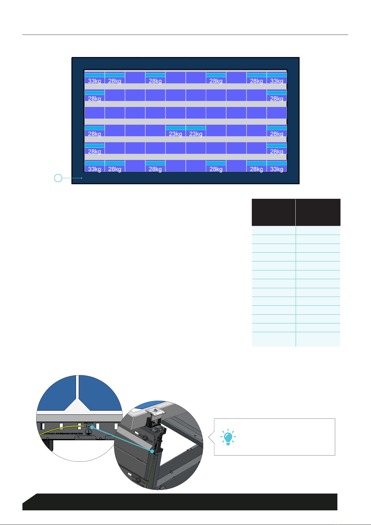
FREE EDGE REGION
NEN 7250 stipulates that solar panels should not be mounted all the way to
the edge of the roof, where strong wind turbulence may occur. The region
around the edge of the roof should therefore be free of solar panels: the
free edge region.
If you are mounting solar panels on roofs over 12 metres, you may need to
take additional measures. Please consult your contact person.
Measure the free edge region from the outer border (see the blue border in
Figure C). You can look up the size of the free edge region in the table. This
information is also available in the ballast plan.
EQUALISATION
The Magnelis steel and the aluminium take care of equalisation. They
prevent tension from building up in the material and failures from occurring
in the inverters or microinverters. (NEN 1010:2015)
TIP: Use this point to earth.
3
Blubase |Lingenstraat 9 |8028 PM Zwolle, Nederland |T. (+31) 085-8000 501 |[email protected] |www.blubase.com
ManualConnect Landscape
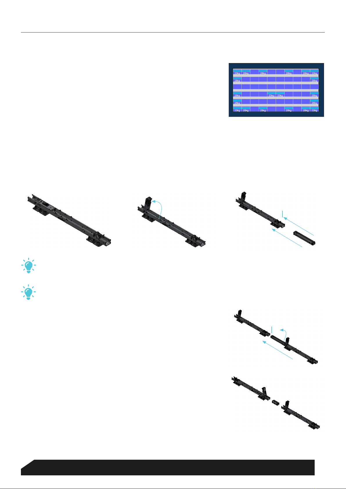
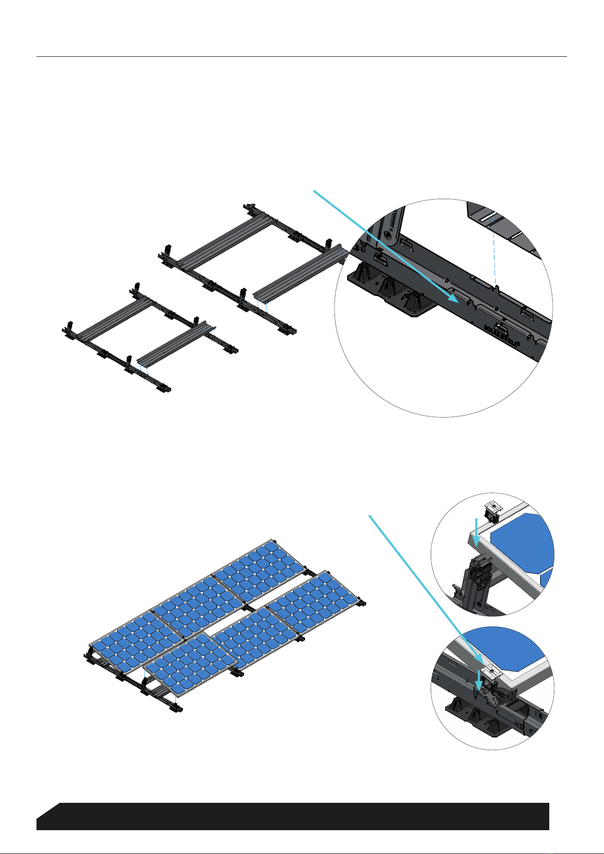
ake the basic component and always click the stand to its upright position rst. Place the basic component on the
rst mounting point. Next, take the connector and click it into place at the front. Please note: you should be able to
hear a clear click, which means that the barb entered into the hole correctly.
STAP 2
Use the mounting plan and the ballast plan from the Blubase calculation
tool. Determine the rst mounting point within the free edge region (see
Page 5) and continue working North to South from there.
STAP 1
Upright stand
TIP: If you are working on a gravel roof, consider the use of our raising blocks. These blocks t neatly
underneath the bases of a basic component. As a result, the mounting system will be raised and will not
move.
TIP: It is crucial that you maintain straight lines and 90-degree angles when mounting. Only then will the
solar panels connect to the stands. One solution is to use a mason’s line; see the example.
Connect the second basic component to the rst and click another
connector into place. Continue with the next basic components and
connectors until the rst row has been nished according to the mounting
plan.
STAP 3
First stand up,
then connect
In case of an East-West set-up, you must rotate the basic component and
use the East-West connector. Move the stand to its upright position before
you click the connectors into place.
EAST-WEST SET-UP
CLICK CLICK
CLICK
MOUNTING PLAN
UNDERLYING ELEMENTS
4
Blubase |Lingenstraat 9 |8028 PM Zwolle, Nederland |T. (+31) 085-8000 501 |[email protected] |www.blubase.com
ManualConnect Landscape
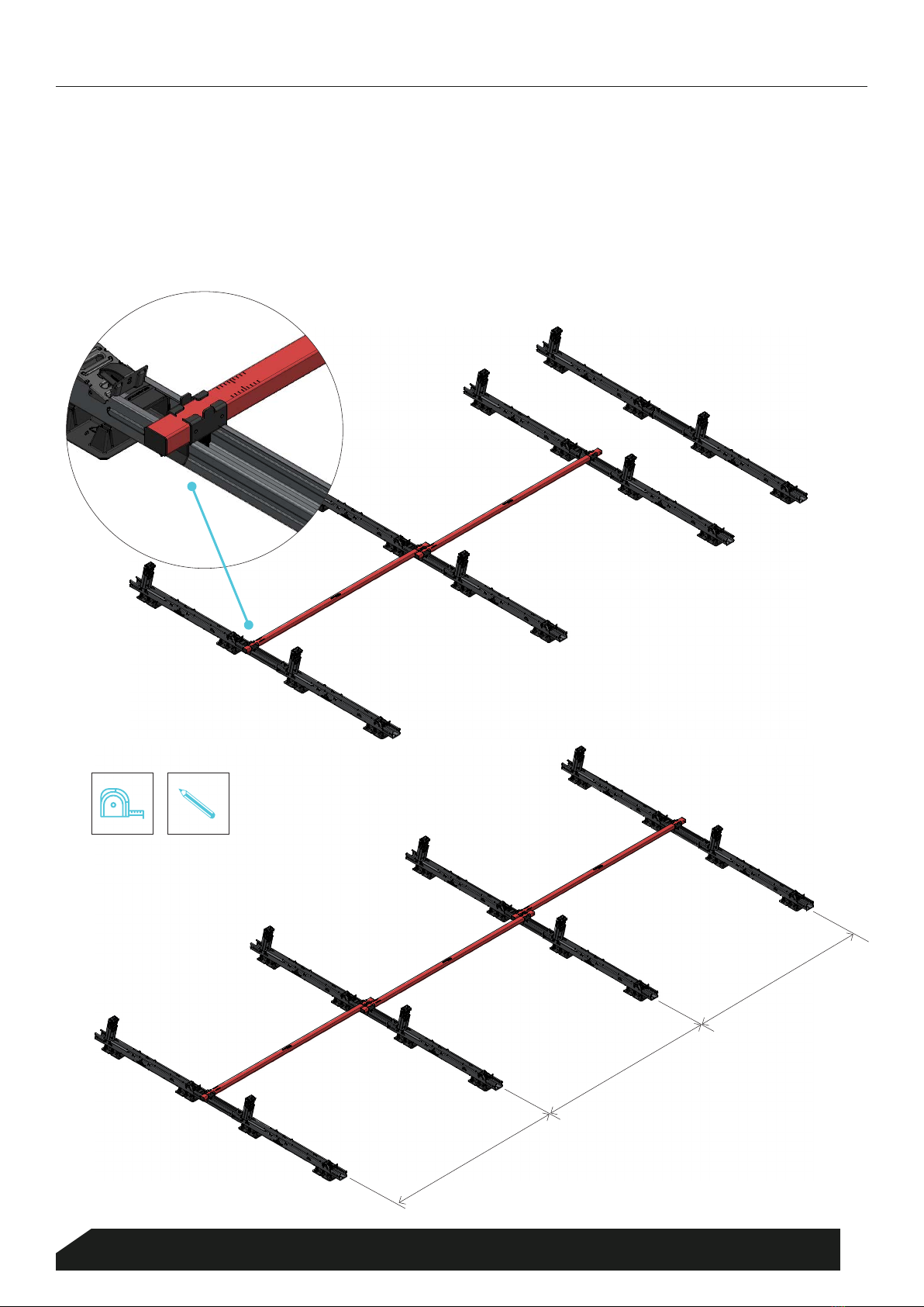
Place the second row in the exact same way as the rst row. The length of the solar panel determines the spacing
between the rows. Place the second row in the exact same way as the rst row. The length of the solar panel
determines the spacing between the rows. Determine the exact distance using the Measuring prole.
Repeat these steps for all rows to carry out the mounting plan. The next page contains instructions on using the
Measuring prole.
STAP 4
Solar panel dimensions
Solar panel dimensions
Solar panel dimensions
5
Blubase |Lingenstraat 9 |8028 PM Zwolle, Nederland |T. (+31) 085-8000 501 |[email protected] |www.blubase.com
ManualConnect Landscape
Place the Measuring prole (A) across
the breadth of the panel, push home
the slide (B) and turn it tight using
the knob (C).
(B) Slide
TIP:
From the outset, be sure to use right angles of
90º. If you do, the mounting system will always be
straight and the solar panels will always t.
(C) Turn
(A)
USING THE MEASURING PROFILE
6
Blubase |Lingenstraat 9 |8028 PM Zwolle, Nederland |T. (+31) 085-8000 501 |[email protected] |www.blubase.com
ManualConnect Landscape
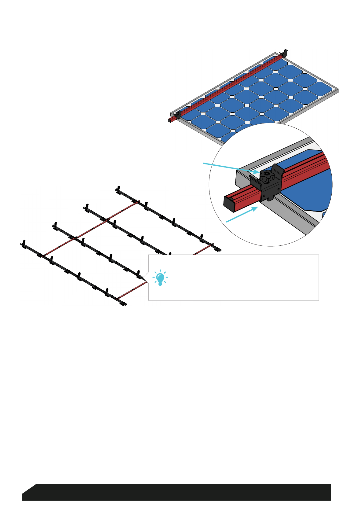
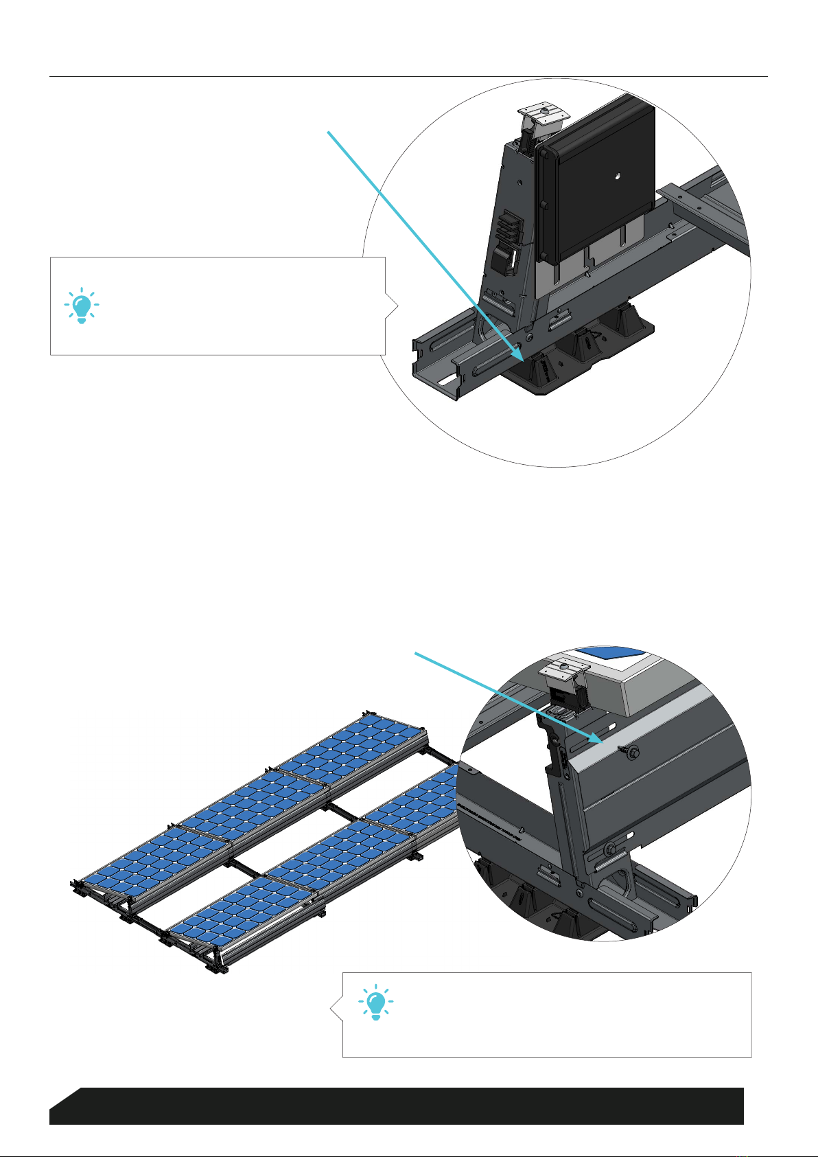
Place the ballast boxes containing the ballast in accordance with the mounting plan. It is not required to screw
down the boxes. However, you are advised to do so in case of large projects, as this process prevents the system
from moving. The basic component has already been tted with rough-drilled holes.
STAP 5
Torque: 5Nm
Place the solar panels against the mounting points. Next, conceal the cables in the cable management system.
STAP 6
Click the clamps into the basic component and turn them tight (torque of 8–10 Nm).
* There is little dierence between mounting landscape and portrait set-ups. In case of portrait mounting, there are three clamp positions and
two stands.
BALLAST BOXES
SOLAR PANELS
7
Blubase |Lingenstraat 9 |8028 PM Zwolle, Nederland |T. (+31) 085-8000 501 |[email protected] |www.blubase.com
Torque: 8-10Nm

ManualConnect Landscape
Place the string cable through the upper ridge of the cable conductor at the inside of the stand. It should be easy to
place the return cable on the outside through the front cable conductor. The cable tray contains a shielded area for
the other cables.
STAP 7
A cable clip has
already been
pre-mounted.
CABLE MANAGEMENT
8
Blubase |Lingenstraat 9 |8028 PM Zwolle, Nederland |T. (+31) 085-8000 501 |[email protected] |www.blubase.com
ManualConnect Landscape
TIP:
Are you using optimisers or micro-
inverters? Place them in the base of the
basic component and slide them into
place until they click.
TIP:
It goes without saying that you do not need a rear
plate for an East-West set-up, as the solar panels
will protect against the wind themselves.
Torque: 5Nm
CLICK
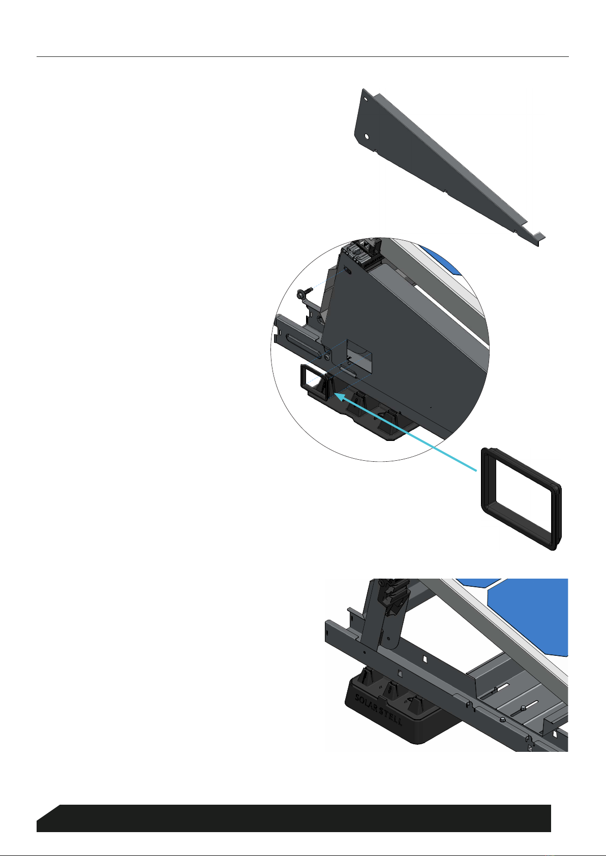
Place the rear plates in the fastening points at the bottom of the stand. Each stand has two rough-drilled threaded
holes (top and bottom). Use both for the stands at the edge of the eld, but only the top one for the stands in the
centre. The screw torque is 5 Nm.
STAP 8
REAR PANELS
9
Blubase |Lingenstraat 9 |8028 PM Zwolle, Nederland |T. (+31) 085-8000 501 |[email protected] |www.blubase.com
ManualConnect Landscape
SIDE PANELS (OPTIONAL)
Side plates are optional. When using them, click
them into the bottom of the basic component
and fasten them to the mounting point of the
stand using a single screw.
STAP 9
GROMMET (OPTIONAL)
Grommets are available for side plates and
basic components. They conduct the cables
without risking cut-ins or cracks.
STAP 10
RAISING BLOCK (OPTIONAL)
If you are working with gravel or you wish to
elevate the mounting system for another
reason, consider the use of our raising blocks.
They t neatly underneath the bases of a basic
component.
STAP 11
10
Blubase |Lingenstraat 9 |8028 PM Zwolle, Nederland |T. (+31) 085-8000 501 |[email protected] |www.blubase.com

ManualConnect Landscape
Description
Center-to-
center
Landscape
Center-to-
center
Portrait
Spacing
East-West Connector
Article No 500050 2300 2980 n/a
1320 Connector
Article No 500013 1320 2000 320
1500 Connector
Article No 500015 1500 2180 500
1700 Connector
Article No 500017 1500 2380 700
E130
B
A
G
C F
Landscape
Portrait
E
100
D
DSpacing
Centre-to-centre
Measurements
A 50 mm
B 32 mm
C 70 mm
D
1145 mm landscape
1826 mm portrait
E 305 mm
F 140 mm
G 190 mm
11
Blubase |Lingenstraat 9 |8028 PM Zwolle, Nederland |T. (+31) 085-8000 501 |[email protected] |www.blubase.com
ManualConnect Landscape
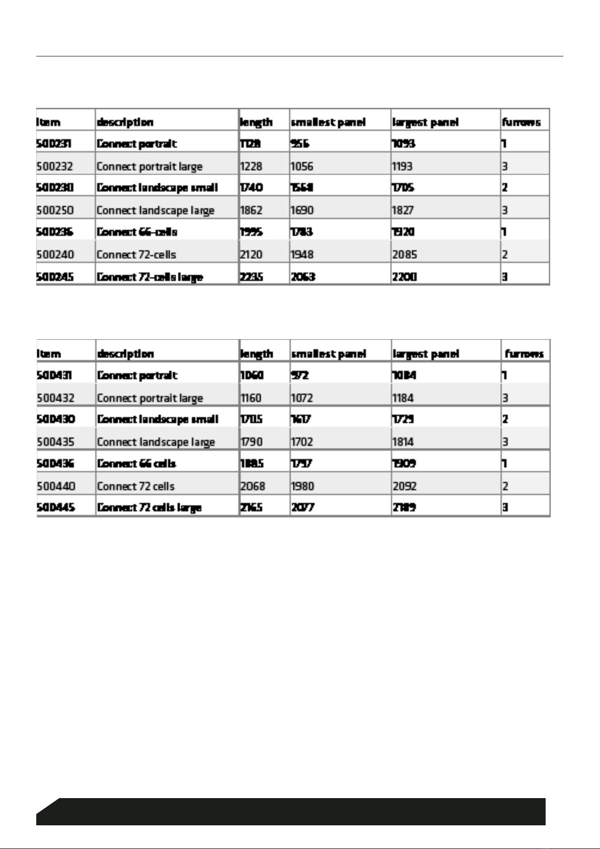
BACK PLATES
BALLAST BOXES
* above 1620mm the PV-panel is no longer supported at the bottom. Check the manual if this is allowed.
12
Blubase |Lingenstraat 9 |8028 PM Zwolle, Nederland |T. (+31) 085-8000 501 |[email protected] |www.blubase.com

ManualConnect Landscape
BLUBASE
DISCLAIMER
••This manual is a general guide (and is therefore not specic to one project) for the straightforward and
ecient installation of solar panels using the Blubase mounting system. No rights may be derived from
this manual.
••For the installation of the Blubase connect mounting system the buildings should have a height of
max. 12 metres. If the building is taller, please contact Blubase in advance for a project-specic,
customised solution.
••If a at roof is sloping more than four degrees, the Blubase connect mounting system must be
secured/anchored to prevent movement.
••An online calculation tool is available for the ballast calculation. Although this tool was developed in
collaboration with the TNO Bouw research organisation according to NEN 7250, the results should be
used as a guideline only. Blubase does not supply any ballast material.
••Installing solar panels on an existing building will change its structural load and/or construction.
We therefore recommend that the structural calculations for an existing building are updated by a
specialist, taking into account the solar panels to be placed and current regulations such as NEN6702,
NEN7250, NEN1991-1-4+A1+C2:2011/NB:2011 and NPR 6708:2013 in particular for wind, snow and
water loads.
••The building insurer must be contacted in advance.
••The following building-related elements should be checked and approved in view of the existing
structural arrangements:
••The additional weight load of the entire PV system that will be installed
••Geometry change of the roof surface
••Wind pressure, snow load and water load, with simulation of accumulations
••The loads for the structure, roof coverings and insulation during the installation
••The suitability of the roof covering and insulation (point pressure) at the contact points between
the mounting system and the existing construction
••The consequences of the thermal interaction between the building and the PV system
••The consequences of any vibrations of the building and/or PV system
IMPORTANT
13
Blubase |Lingenstraat 9 |8028 PM Zwolle, Nederland |T. (+31) 085-8000 501 |[email protected] |www.blubase.com
Table of contents
Other blubase Inverter manuals


Popular Inverter manuals by other brands


Bosch
Bosch CLIMATE 5000 VRF RDCI8/25-3 user manual

KUSSMAUL
KUSSMAUL 450-0700-0 instruction manual

Haier
Haier SUPER MATCH AS35S2SF1FA-BC Service manual

Modena
Modena SolarPad SL OGD Series User manual book

Generac Power Systems
Generac Power Systems SD150 Specifications

Sungrow
Sungrow SG110CX Quick installation guide