GCL GCL-P6/60GD Series User manual

Version: GCL/XXJC/2-RD-357_B2
Bifacial Module Installation Manual for
GCL System Integration Technology Co., Ltd.

GCL System Integration Technology Co., Ltd.
Bring Green Power to Life
01
CONTENTS
Purpose of this Manual...........................................................................................................2
Disclaimer .............................................................................................................................2
Safety & Transport.................................................................................................................3
Mechanical Installation..........................................................................................................7
Electrical Installation ...........................................................................................................20
Grounding............................................................................................................................22
Bypass Diodes and Block Diodes.........................................................................................23
Maintenance ........................................................................................................................24

GCL System Integration Technology Co., Ltd.
Bring Green Power to Life
02
PURPOSE OF THIS MANUAL
This manual applies exclusively to the bifacial module (here in after referred to as
Module) of GCL System Integration Technology Co., Ltd. (here in after referred to as
GCLSI). The contents of this manual involve the installation methods, operation safety
and maintenance information of GCLSI’s Modules.
Modules must be installed by professionals. Please read this manual carefully before
installation. The installers must follow all the rules in this manual strictly as well as local
requirements and regulations by law or authorized organizations.
Before installing, the installer must be familiar with their mechanical and electrical
requirements. Please keep this manual in a safe place for future reference (care and
maintenance) and in case of sale or disposal of the Modules.
DISCLAIMER
GCLSI shall not be responsible for any loss arising from the installation, operation, use or
maintenance of the Modules which is not complying with the guidance of this manual,
including breakdown or damage of the Modules or any other expenses incurred.
Any customer shall not get any patent or authorization of the patent when using the
Modules, expressed or implied. Any infringement of patents or other rights of the third
party, which may result from the use of the Module, is not within the responsibility scope
of GCLSI. The information in this manual is based on GCLSI’s knowledge and
experience and is believed to be reliable, but such information including product
specification (without limitation) and relevant suggestions do not constitute a warranty,
expressed or implied.
GCLSI reserves the rights to change the manual, the Modules, the specifications or any
other information of the Modules without prior notice.

GCL System Integration Technology Co., Ltd.
Bring Green Power to Life
03
SAFETY & TRANSPORT
General Detailed Rules
Keep all the Modules and electrical connectors clean and dry before installation.
Use both hands to carry Modules. Do not overlap Modules.
Be cautious when carrying Modules. Slip-proof gloves are necessary.
Use supportive disassembling tools when unpacking.
The application level of GCLSI module is Class A, which can be used in systems operating at
greater than 50 V DC or 240W, where general contact access is anticipated;
Do not stamp on Modules or put weight on Modules.
Do not disassemble or drop Modules. Do not remove any nameplate or component
of the module.
Do not use mirrors or magnifiers to concentrate sunlight onto Modules.
Do not lift the module by grasping the junction box or cable wire.
Do not use any sharp object with Modules.
Do not directly apply pressure on the glass surface or backsheet of Modules.
Do not touch the surface of the coated glass with bare hands.
Ensure all contacts and the operating environment are clean and dry.
Module Carry and Installation Instruction
Both hands when handling Modules
Ensure Modules are fixed properly
Do not use sharp objects with Modules
Do not pull the wiring cables or junction
box
Do not stamp on Modules
Do not touch Modules with bare or dirty
hands
Do not pile up Modules on uneven ground
Do not drop or throw Modules

GCL System Integration Technology Co., Ltd.
Bring Green Power to Life
04
SAFETY & TRANSPORT
Description of Package Signs
Before the operation, it is necessary to read carefully the unpacking instruction and outer
packing box instruction, and carry out the operation as instructed.
1. DO NOT expose the module to rain or
moisture.
2. The Modules in the carton box are fragile.
Handle with care.
3. The package shall never be upside down
during the transportation.
4. It is prohibited to tramp on the packing
box and module.
5. During the stacking of the Modules, the
outer packing box can be stacked not
exceed the maximum layer allowed .(n=2
means it is allowed to stack for at most
two layers.)
6. One module shall be handled by two
people together.
n

GCL System Integration Technology Co., Ltd.
Bring Green Power to Life
05
SAFETY & TRANSPORT
Unloading, Transportation and Storage
When the Modules are delivered to the project site, the freight car shall be ready in the
flat, even and open area for parking and unloading.
Forklift unloading: Choose the appropriate carrying forklift according to the commodity
weight, unload the Modules from the freight car and place them on flat ground.
Unloading with a crane: Affix the lifting belt in the wood supporting frame buckle (Fig. 1,
2). It is allowed only to lift one pallet at a time. Before lifting, it is necessary to confirm
whether the pallet and paper box are damaged and ensure that the lifting rope is robust
and firm. When being lifted close to the ground, the paper box will be gently placed in a
relatively flat position on the project site by two people, one on each side.
Figure 1 Wood Supporting Frame Figure 2 Lifting Schematics
It is prohibited to stack the Modules in the project site.
During the transportation at the project site, the Modules shall not be stacked, but only
allowing for one layer in transportation.

GCL System Integration Technology Co., Ltd.
Bring Green Power to Life
06
SAFETY & TRANSPORT
Storage in the project site warehouse:
Storage environment requirements: Humidity<85%, temperature -20 ~+50℃; Modules
statically stacked for ≤2 layers.
Temporary storage at the project site: The Modules shall be stored in a dry,
well-ventilated place. They shall not be stacked but shall be covered with waterproof
cloth to prevent dampness in the Modules.
Unpacking description
1. In the outdoor unpacking process, it is prohibited to operate in rainy conditions;
2. If there is wind in the field, special attention shall be paid. Particularly in the event of
heavy wind, it is recommended not to handle the module, and it is necessary to properly
secure the unpacked Modules;
3. The working surface shall be such that the packing box can be placed in a stable, level
position, avoiding being overturned;
4. During the unpacking, it is necessary to wear protective gloves, and avoid scratching
the hands and leaving the fingerprints on the glass;
5. In the case of operation not according to the requirements or in the case of an
unskillful operation, it will result in the fall-off of the protective corner in small amounts,
which will be normal. The effect of the protective corner is to reduce damage due to external
force during transport, and the fall-off of the protective corner will not influence the reliability
of the Modules;
6. Before the unpacking, it is necessary to carefully check the product information on the
carton box, and carefully read the unpacking instruction;
7. Every module shall be carried by two people. When carrying the module by two
people, it is prohibited to pull the junction box.

GCL System Integration Technology Co., Ltd.
Bring Green Power to Life
07
MECHANICAL INSTALLATION
Location Selection
Select suitable places to install Modules. The module in the north latitude region shall
face south, and shall face north in the south latitude region.
Install Modules at the places with sufficient sunlight and without shade at any time. If a
module is shaded or even partially shaded, it will result in lower power output. A
permanent or regular shade will cause module damage, which will result in the invalidity
of product’s limited warranty.
Do not store, install or use Modules at the places where combustible gas is easily
generated or gathering.
The straight-line distance between the installation site and coastline shall not be shorter
than 1 km unless there is a writ ten approval from GCLSI or an engagement specified in
the contract.
Location Selection
Modules in the same string should be installed at the same angle. Modules installed in
different angles will receive different irradiation, which will cause current different. As a
result, it will decrease the operation efficiency of the system.
Please refer to Table 1 for the recommended mounting tilt angles of the Modules.
Local latitude
Mounting Tilt Angles
0°-15°
15°
15°-25°
Local latitude
25°-30°
Local latitude + 5°
30°-35°
Local latitude + 10°
35°- 40°
Local latitude + 15°
>40°
Local latitude + 20°
Table 1 Mounting Tilt Angle of Modules

GCL System Integration Technology Co., Ltd.
Bring Green Power to Life
08
MECHANICAL INSTALLATION
Installation requirements
The installation structure shall be made of the durable 、corrosion-resistant and
ultraviolet-resistant materials. It is necessary to ensure that the support and structure in
use have been tested, certified and approved.
No matter where the Modules are installed, it is necessary to ensure that the module is
firmly mounted on the support, and ensure that it can undertake the corresponding wind
loading and snow loading.
Choose proper installation height of the photovoltaic support system, the lower part of the
module should not be covered with snow for a long time in winter. Additionally, it is
necessary to ensure that the lowest part of the module is high enough, to avoid being
shaded by the plant or damaged by the flying sand.
For the photovoltaic system installed on the ground, GCLSI recommends that the
minimum distance from the module bottom to the ground surface shall be 24 inches
(60cm). The higher the lower point of the module from the ground, the higher the power
generation efficiency on the back of the module. When the module is installed on the roof,
it is necessary to ensure that the roof structure is suitable and the installed module shall
not be beyond the roof zone. Additionally, the roof shall be have water-proof treatment to
prevent the roof from water leakage.
If the module will be installed on the column, the chosen column and the module support
structure shall be able to undertake the locally expected loads of wind and snow. Ensure
that such loads are within the range of the respective maximums loading permitted by
GCLSI, meanwhile, the module will not be subjected to the thermal expansion force from
the support structure. The stacking of Modules shall be prohibited.
The back of the module shall be well ventilated to facilitate the cooling of the module.
GCLSI recommends that there shall be the gap of 30cm between the module and the
installation surface, if the surface is finished with the light-color and highly reflective
materials such as white paint and aluminum foil, the back of the module could contribute
5%-30% additional power output.
To prevent the influence of thermal expansion between the Modules upon the module,
GCLSI recommends that the minimum distance between two Modules shall not be less
than 10mm, which is the minimum linear distance between two Modules.
It is necessary to always observe the instruction guide and safety rules attached for
module installation.
It is prohibited to drill the holes in the glass surface. Otherwise, it will invalidate the
quality guarantee.

GCL System Integration Technology Co., Ltd.
Bring Green Power to Life
9
MECHANICAL INSTALLATION
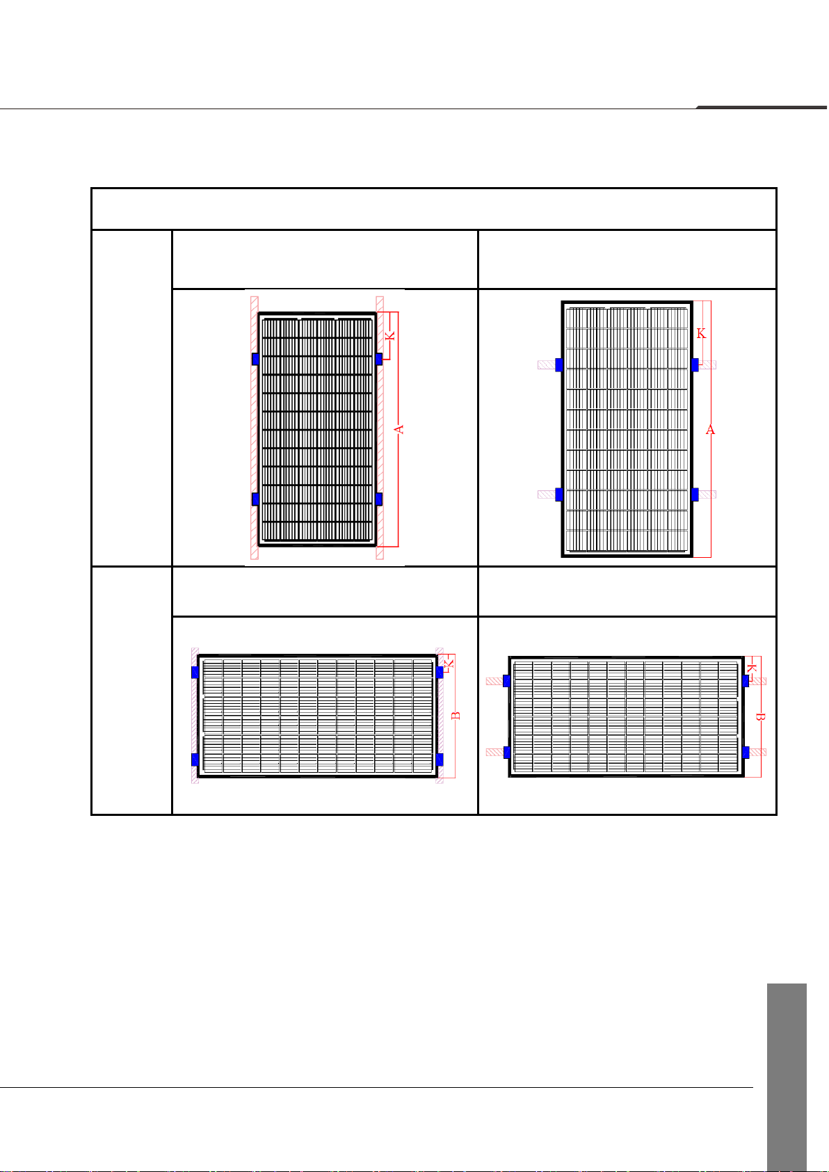
Installation Method
1、Modules without frames
Installation with the mounting clamp
Table 2 Installation Method
Clamping
on the
long side
Installation Method A
Installation Method B
Table 3 Installation method and load capacity
Module Type
Module
dimensions
(mm)
Length of
the clamp
(mm)
Installation Method A
Installation Method B
Position of
clamp K
(mm)
Design load :
downward/
upward,
γm=1.5
(Pa)
Position of
clamp K
(mm)
Design load :
downward/
upward,
γm=1.5
(Pa)
GCL-P6/60GDXXX
GCL-M6/60GDXXX
1658*992*6
150
300-400
2400
1600
300-400
3600
1600
1680*1000*6
GCL-N6/60GXXX
1658*992*6
150
300-400
2400
1600
300-400
3600
1600
GCL-P6/72GDXXX
GCL-M6/72GDXXX
1968*992*6
200
400-500
2400
1600
400-500
3600
1600
2000*1000*6
GCL-N6/72GXXX
1968*992*6
200
400-500
2400
1600
400-500
3600
1600
GCL-P3/60GDXXX
GCL-M3/60GDXXX
1700*1000*6
150
300-400
2400
1600
300-400
3600
1600
GCL-P3/72GDXXX
GCL-M3/72GDXXX
2030*1000*6
200
400-500
2400
1600
400-500
3600
1600
GCL-M/P3/60GTXXX
1700*1034*6
150
300-400
2400
1600
300-400
3600
1600
GCL-M10/60GTXXX
1980*1166*6
200
400-500
2400
1600
400-500
3600
1600
Note: Test load = γm(safety factors) ×design load

GCL System Integration Technology Co., Ltd.
Bring Green Power to Life
10
MECHANICAL INSTALLATION
The installation of the double-glass bifacial module shall match the photovoltaic support
design and the customized accessories, and comply with the system design requirements.
It is necessary to use the specified clamp for the module installation, and the torque force
shall meet the requirements.
Horizontal installation: the first module and the last module of every row shall be fixed
with the side-clamp, and the Modules in the middle should be fixed by middle-clamp.
Vertical installation: the first module and the last module of every line shall be fixed with
the side-clamp, and the Modules in the middle should be fixed by middle-clamp.
To avoid the clamp producing the shade on the front or back of the module.
side-clamp
middle-clamp
Figure 3 Structural breakdown schematics of
side-clamp
Figure 4 Structural breakdown schematics
of middle-clamp
Installation tool: 13mm socket wrenches (electric wrenches optional), torque wrenches
10-100 N.M; Tightening torque of the clamp: 16 N.M~20N.M.
Side clamp, middle clamp: including lower and upper EPDM blocks, fastener
combination (M8 bolt, washer, spring washer, nut).

GCL System Integration Technology Co., Ltd.
Bring Green Power to Life
11
MECHANICAL INSTALLATION
Read the following installation procedure contents and be familiar with full procedure
before installation. Additionally, get the field preparation works ready prior to installation
starts. The module may be installed horizontally and vertically.
Installation steps
Step 1: install the
support.
Install the track
support.
Step 2: Install the
clamp.
Fix the clamp on the
support with the nut
not tightened.

GCL System Integration Technology Co., Ltd.
Bring Green Power to Life
12
MECHANICAL INSTALLATION
Step 3: Install the
module.
Install the module
into the clamp as
required , and tighten
the nut with the
torque of the clamp:
16 N.M~20 N.M.
GCL System Integration Technology Co., Ltd.
Bring Green Power to Life
13
MECHANICAL INSTALLATION
2、Framed Modules
Installation with the mounting clamp
Table 4 Installation Method
Clamping
on the
long side
Installation Method C
Installation Method D
Clamping
on the
short side
Installation Method E
Installation Method F
Note: The length of the clamp≥50mm.

GCL System Integration Technology Co., Ltd.
Bring Green Power to Life
14
MECHANICAL INSTALLATION
Table 5 Installation method and load capacity
Installation Method
Installation Method C
Installation Method D
Installation Method E
Installation Method F
Module Type
Module
dimensions
(mm)
Position
of
clamp
K
(mm)
Design
load :
downward/
upward,
γm=1.5
(Pa)
Position
of
clamp
K
(mm)
Design
load :
downward/
upward,
γm=1.5
(Pa)
Position
of
clamp
K
(mm)
Design
load :
downward/
upward,
γm=1.5
(Pa)
Position
of
clamp
K
(mm)
Design
load :
downward/
upward,
γm=1.5
(Pa)
GCL-P6/60GDFXXX
GCL-M6/60GDFXXX
1664*998*30
366-466
3600
1600
366-466
3600
1600
25~250
1600
1600
25~250
1600
1600
1686*1002*30
372-472
372-472
25~251
25~251
GCL-P6/72GDFXXX
GCL-M6/72GDFXXX
1974*998*30
444-544
3600
1600
444-544
3600
1600
25~250
1600
1600
25~250
1600
1600
2006*1002*30
452-552
452-552
25~251
25~251
GCL-P3/60GDFXXX
GCL-M3/60GDFXXX
1706*1002*30
377-477
3600
1600
377-477
3600
1600
25~251
1600
1600
25~251
1600
1600
1706*998*30
377-477
377-477
25~250
25~250
GCL-P3/72GDFXXX
GCL-M3/72GDFXXX
2036*1002*30
459-559
3600
1600
459-559
3600
1600
25~251
1600
1600
25~251
1600
1600
2026*998*30
457-557
457-557
25~250
25~250
GCL-P6/60DHXXX
GCL-M6/60DHXXX
1686*1000*35
372-472
3600
1600
372-472
3600
1600
25~250
1600
1600
25~250
1600
1600
1666*1000*35
367-467
367-467
25~250
25~250
GCL-P6/72DHXXX
GCL-M6/72DHXXX
2010*1000*35
453-553
3600
1600
453-553
3600
1600
25~250
1600
1600
25~250
1600
1600
1980*1000*35
445-545
445-545
25~250
25~250
GCL-P3/60DHXXX
GCL-M3/60DHXXX
1706*1000*35
377-477
3600
1600
377-477
3600
1600
25~250
1600
1600
25~250
1600
1600
1686*1000*35
372-472
372-472
25~250
25~250
GCL-P3/72DHXXX
GCL-M3/72DHXXX
2036*1000*35
459-559
3600
1600
459-559
3600
1600
25~250
1600
1600
25~250
1600
1600
2010*1000*35
453-553
453-553
25~250
25~250
GCL-M8/72GDFXXX
GCL-P8/72GDFXXX
2130*1048*30
483-583
3600
1600
483-583
3600
1600
25-262
1600/1600
25-262
1600/1600
2094*1038*35
473-573
3600
1600
473-573
3600
1600
25-260
1600/1600
25-260
1600/1600
GCL-M8/72DHXXX
2130*1048*35
483-583
3600
1600
483-583
3600
1600
-
-
-
-
GCL-M10/72GDFXXX
2256*1133*35
-
-
514-614
3600
1600
-
-
-
-
2278*1134*35
2279*1134*35
2278*1134*30
-
-
520-620
-
-
GCL-M10/60GDFXXX
1890*1133*35
-
-
422-522
3600
1600
-
-
-
-
1908*1134*30
-
-
427~572
3600
1600
-
-
-
-
GCL-M12/60GDFXXX
2172*1303*35
-
-
493-593
3600
1600
-
-
-
-
GCL-M12/66GDFXXX
2384*1303*35
-
-
546-646
3600
1600
275-375
-
275-375
1600/1600
Note: Test load = γm(safety factors) ×design load

GCL System Integration Technology Co., Ltd.
Bring Green Power to Life
15
MECHANICAL INSTALLATION
Installation with the mounting hole
Table 6 Installation Method
Mounting
on the
long side
Installation Method G
Installation Method H

GCL System Integration Technology Co., Ltd.
Bring Green Power to Life
16
MECHANICAL INSTALLATION
Table 7 Mounting dimension and load capacity
Module Type
Module dimensions
(mm)
Mounting
distance M
(mm)
Mounting
distance N
(mm)
Installation
Method G
Installation
Method H
Design load :
downward/
upward, γm=1.5
(Pa)
Design load :
downward/
upward, γm=1.5
(Pa)
GCL-P6/60GDFXXX
GCL-M6/60GDFXXX
1664*998*30
990
962
3600/1600
3600/1600
1300
962
1600/1600
1600/1600
1686*1002*30
860
966
3600/1600
3600/1600
1360
966
1600/1600
1600/1600
GCL-P6/72GDFXXX
GCL-M6/72GDFXXX
1974*998*30
400
962
1600/1600
1600/1600
990
962
3600/1600
3600/1600
1300
962
1600/1600
1600/1600
2006*1002*30
400
962
1600/1600
1600/1600
860
966
3600/1600
3600/1600
1360
966
1600/1600
1600/1600
GCL-P3/60GDFXXX
GCL-M3/60GDFXXX
1706*1002*30
860
966
3600/1600
3600/1600
1360
966
1600/1600
1600/1600
1706*998*30
860
962
3600/1600
3600/1600
1360
962
1600/1600
1600/1600
GCL-P3/72GDFXXX
GCL-M3/72GDFXXX
2036*1002*30
400
962
1600/1600
1600/1600
860
966
3600/1600
3600/1600
1360
966
1600/1600
1600/1600
2026*998*30
400
958
1600/1600
1600/1600
860
962
3600/1600
3600/1600
1360
962
1600/1600
1600/1600
GCL-P6/60DHXXX
GCL-M6/60DHXXX
1686*1000*35
1666*1000*35
860
951
3600/1600
3600/1600
1360
951
1600/1600
1600/1600
GCL-P6/72DHXXX
GCL-M6/72DHXXX
2010*1000*35
1980*1000*35
400
954
1600/1600
1600/1600
860
951
3600/1600
3600/1600
1360
951
1600/1600
1600/1600
GCL-P3/60DHXXX
GCL-M3/60DHXXX
1706*1000*35
1686*1000*35
860
951
3600/1600
3600/1600
1360
951
1600/1600
1600/1600
GCL-P3/72DHXXX
GCL-M3/72DHXXX
2036*1000*35
2010*1000*35
400
954
1600/1600
1600/1600
860
951
3600/1600
3600/1600
1360
951
1600/1600
1600/1600
GCL-M8/72GDFXXX
GCL-P8/72GDFXXX
2130*1048*30
400
1008
1600/1600
1600/1600
990
1012
3600/1600
3600/1600
1300
1012
3600/1600
3600/1600
2094*1038*35
400
989
1600/1600
1600/1600
990
989
3600/1600
3600/1600
1300
989
3600/1600
3600/1600

GCL System Integration Technology Co., Ltd.
Bring Green Power to Life
17
MECHANICAL INSTALLATION
Note: Test load = γm(safety factors) ×design load
Module Type
Module dimensions
(mm)
Mounting
distance M
(mm)
Mounting
distance N
(mm)
Installation
Method G
Installation
Method H
Design load :
downward/
upward, γm=1.5
(Pa)
Design load :
downward/
upward, γm=1.5
(Pa)
GCL-M8/72DHXXX
2130*1048*35
400
1002
1600/1600
1600/1600
990
999
1600/1600
1600/1600
1300
999
3600/1600
3600/1600
GCL-M10/72GDFXXX
2256*1133*35
-
-
-
-
990
1084
-
3600/1600
1400
1084
-
3600/1600
2278*1134*35
2279*1134*35
-
-
-
-
990
1085
-
3600/1600
1400
1085
-
3600/1600
GCL-M10/60GDFXXX
1890*1133*35
-
-
-
-
990
1084
-
3600/1600
1400
1084
-
3600/1600
1908*1134*30
990
1085
-
3600/1600
1400
1085
-
3600/1600
GCL-M12/60GDFXXX
2172*1303*35
——
——
——
——
1400
1254
-
3600/1600
GCL-M12/66GDFXXX
2384*1303*35
——
——
——
——
1400
1254
-
3600/1600

GCL System Integration Technology Co., Ltd.
Bring Green Power to Life
18
MECHANICAL INSTALLATION
The Modules may be installed and fixed with the following methods:
Mounting hole system: Use the corrosion-resistant M8 bolt, for fixing with the
installation support through the installation hole in the side frame of the module, as
shown in Fig. 5.
Clamping system: use proper clamp, and fix the module with the installation support, as
shown in Fig. 6.
Figure 5 Mounting holes
Figure 6 Mounting clamps
The mounting accessories recommended are listed below:
Bolt
Flat washer
Spring washer
Nut
Material: stainless
Steel material: stainless steel
Material: stainless steel
Material: stainless steel
Size: M8
Size: M8
Size: M8
Size: M8
The range of torque for screw tightening is 14N.m to 20N.m.

GCL System Integration Technology Co., Ltd.
Bring Green Power to Life
19
MECHANICAL INSTALLATION
Mounting with Single-axis Tracking System
1. This installation is only for 72 cells framed modules.
2. It is a Single-axis Tracking System; the module is fixed on the axis by bolting long
frame.
3. The frame of each module has 4-φ7*12mm mounting holes with specific location
shown in Figure 7.
4. Secure the module in each fixing location with an M6 bolt, two flat washers, a spring
washer and nut as shown in Figure 7, torque: 9~12 N.m.
Figure 7
This manual suits for next models
11
Table of contents
Popular Inverter manuals by other brands


Brusa
Brusa DMC514 Technical Data and Start-Up

LeadSolar
LeadSolar Energy Microinverter LS600 Installation & operation guide

Toshiba
Toshiba TOSVERT VF-AS3 instruction manual

Power One
Power One TRIO-20.0-TL instruction manual

SEW-Eurodrive
SEW-Eurodrive MOVITRAC LTP-B operating instructions

FRONIUS
FRONIUS IG Plus USA operating instructions


