Blue Demon BLUEARC 200STI AC/DC User manual
1
BLUEARC 200STI AC/DC
OWNERS MANUAL
(Plastic Panel)
MCU AC/DC PULSE TIG/MMA WELDING MACHINE

2
WARNING! Please read these instructions before installing and
commissioning the device.
1. GENERAL COMMENTS
Start-up and operation of the device can only be made after carefully reading this
Operator's Manual
Damage to the device due to improper handling will result in the loss of warranty
rights.
It is forbidden to modify devices and interfere in its construction.
ATTENTION
Welding may endanger the safety of the operator and other persons in the vicinity.
Therefore, special precautions should be taken during welding. Before welding, read
the occupational health and safety regulations in force at the workplace.
During electric welding with MMA and TIG methods, there are the following hazards:
• ELECTRIC SHOCK
• NEGATIVE EFFECT OF ARC LIGHT ON EYES AND SKIN
• POISON AND GAS DAMAGE
• BURNS
• NOISE
Prevention of electric shock:
connect the device to a technically efficient electrical installation with proper
protection
assemble current wires with the device switched off,
do not use handles and power cables with damaged insulation,
in conditions of particular danger of electric shock (work in environments with
high humidity and closed tanks) work with a helper supporting the work of the
welder and watching over safety, use clothing and gloves with good insulating
properties
if you notice any irregularities, you should ask competent people to remove
them,
It is forbidden to operate the device with covers removed.
Prevention of the negative impact of the electric arc on the eyes and human
skin:
• Wear protective clothing (gloves, apron, leather shoes),
• Use shields or protective shields with a properly selected filter,

3
• Use protective covers made of non-combustible materials and properly choose
the color of the walls that absorb harmful radiation.
Prevention of poisoning by vapors and gases emitted during welding from
electrode lagging and metal evaporation:
use ventilation devices at work stations
blow with fresh air when working in a confined space
Prevention of burns:
Use appropriate protective clothing and footwear to protect against burns from
arc radiation and spatter
Avoid soiling the clothes with lubricants and oils that may lead to ignition of the
clothing.
Prevention of negative impact of noise:
Use earplugs or other noise protection measures,
Warn of the dangers of nearby people.
Before starting the device:
Check the condition of electrical and mechanical connections. It is forbidden to
use handles and power cables with damaged insulation. Improper insulation
of holders and power cords may result in electric shock,
Ensure proper working conditions, ensure the right temperature, humidity and
ventilation in the workplace. Outside of enclosed spaces, protect against
atmospheric precipitation,
Persons operating the welder should:
have the power to weld electric electrodes with coated electrodes and the TIG
method,
know and follow the health and safety regulations applicable when carrying out
welding work,
use appropriate, specialist protective equipment: gloves, apron, rubber boots,
shield or welding helmet with a properly selected filter,
be familiar with the contents of these operating instructions and operate the
welder for its intended purpose
Any repairs to the device may only be made after disconnecting the plug from the mains
socket. When the device is connected to the power it is not allowed to touch any elements
constituting the welding current circuit with bare hands or through damp clothing. It is
forbidden to remove the external covers when the device is connected to the power.
Maintenance and repair work may only be carried out by authorized persons subject to the
safety and operating conditions applicable to electrical equipment.

4
2. GENERAL DESCRIPTION
The welding machine is used for manual welding by direct current and alternating
structural steels with coated electrodes (MMA method), as well as quality steels and
non-ferrous metals in the inert gas shield (TIG method). In the design and
construction of the device the latest developments in the field of PWM technology
(pulse width modulation) and IGBT modules (bipolar transistors with an insulated
gate) were used, thanks to which the welder is characterized by small size and low
weight.
The ARC FORCE function is available during MMA welding. During TIG welding it is
possible to regulate the rise and fall of current, pre-outflow and gas outflow as well as
pulse and AC current parameters. The device has a memory of 10 sets of parameter
settings for the TIG HF and MMA methods.
3. TECHNICAL PARAMETERS
3.1Machine
Model
BLUEARC 200STI AC/DC
Power supply voltage
AC 230V ±10% 50Hz/60Hz
AC 110V ±10% 50Hz/60Hz
Max. Power consumption
MMA: 5,7 KVA, TIG: 4,1 KVA
MMA: 4,0 KVA, TIG: 3,1 KVA
Welding current / work cycle
MMA: 180 A / 60%
TIG: 200 A / 60%
MMA: 120 A / 60%
TIG: 140 A / 60%
No-load voltage
67 V
67 V
Power consumption
MMA: 24,0 A, TIG 19,0 A
MMA: 50,0 A, TIG 37,0 A
Weight
17 kg
Dimension
510 x 210 x 380 mm
Protection Class
IP23
3.2 Parameters adjustment ranges
Model
BLUEARC 200STI AC/DC
Power supply voltage
AC 230V ±10% 50Hz/60Hz
AC 110V ±10% 50Hz/60Hz
Arc Force
0 – 100 A
0 – 100 A
Pre gas flow time
0,1 – 15 s
0,1 – 15 s
Post gas flow time
0,1 – 15 s
0,1 – 15 s
Up slope time
0 – 15 s
0 – 15 s
Down slope time
0 – 15 s
0 – 15 s
Start current
5 – 200 A
5 – 140 A
Current
MMA: 20-180 A TIG:5-200 A
MMA: 20-120 A TIG:5-140 A
Base Current
5 – 200 A
5 – 140 A
Stop current
5 – 200 A
5 – 140 A
Pulse frequency
0,5 - 999 Hz
0,5 - 999 Hz
Pulse Duty
10 – 90 %
10 – 90 %
AC Frequency
1 – 250 Hz
1 – 250 Hz
AC Balance width
15 – 50 %
15 – 50 %
Spot time
0,1 – 15 s
0,1 – 15 s

5
Level of security
IP determines to what extent the device is resistant to solid and water contamination.
IP23 means that the device is designed to work indoors and is not suitable for use in
the rain.
(Plastic Panel)
4. CONSTRUCTION AND OPERATION
The basis for the construction of the welding power conversion system are electronic
circuits made in IGBT technology that enable operation in the frequency range above
50kHz. The principle of operation consists in straightening the single-phase voltage
of the power supply network to DC voltage, converting the obtained direct voltage
into a high-frequency rectangular waveform, transforming the voltage into the range
required by the welding process and re-straightening the received voltage to DC
voltage.
The welder is equipped with a power supply compensation circuit, which allows them
to be operated at voltage fluctuations in the supply network up to 10%.

6
5. PREPARATION OF THE DEVICE FOR WORK
If the device is stored or transported in low temperatures, the device should be
brought to the right temperature before starting work !!!
5.1MMA Method
The ends of the welding cables should be connected to the sockets (1) and (5)
on the front panel, so that the polarity of the electrode is on the electrode holder.
The polarity of the welding cable connection depends on the type of electrode
used and is given on the electrode packaging. The ground cable clamp must be
securely attached to the welded material. Connect the device's plug to a 110V or
230V 50Hz/60Hz mains socket.
5.2Tig Method
The tig torch should be connected to the negative polarity socket (1), carefully screw the
control plug of the holder to the socket (3) and the gas connection to the quick connector
socket (2). The gas pipe from the reducer should be led and attached to the gas
connector (9) located on the back of the housing. Connect the positive pole of the source
(5) to the material to be welded with a wire with a earth clamp. Connect the device's plug
to a 110V or 230V 50Hz/60Hz mains socket.

7
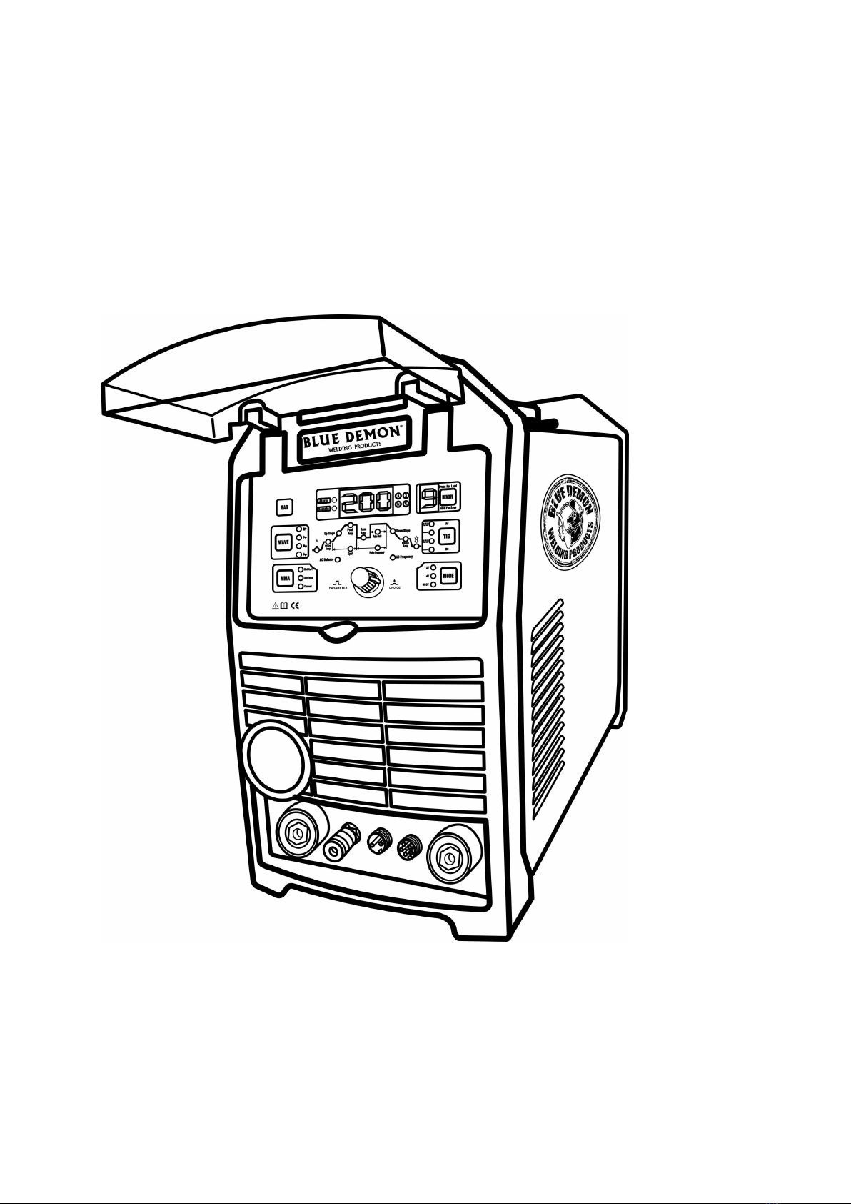
6. DESCRIPTION OF OPERATION
Front and rear panel
(1) Tig torch handle control socket (2) gas connector
(3) Negative polarization socket (4) remote socket (5) positive polarization socket
(6) switch on/off (7) ground terminal (8) supply power wire (9) spigot shield gas
6.1 CONTROL PANEL
B A I H G F
C D E

8
A –Gas check button
The button is used to check if the Gas is having or not. Press the button, Gas will output; release the
button Gas will close.
B – AC Wave Selection (Note: This action is working for TIG AC working mode only.)
- sine wave, typical wave
- rectangular wave – the most popular wave
- trapezoidal wave – soft arc
- triangular wave - used for thin materials
C – MMA mode Selection
The button is used to select the MMA welding parameters, Arc Force, Hot Start and welding Current.
D – Control knob
The adjustment knob is used to change the welding parameters.
Short push of the knob causes a transition between the set parameters. The currently adjustable
parameter is marked by ignition of the corresponding diode, and the current parameter value appears
on the parameter display (I). Turning the knob to the left decreases and turning to the right increases
the value of the parameter. Pressing the knob again will save the parameter value and move to the
next parameter.
E – Work selection button (2T/4T/SPOT)
(Note: 2T/ 4T/SPOT action is working for TIG working mode only.)
In the two-stroke mode, pressing the switch in the grip handle will activate the ionizer and ignite the
arc. Welding is carried out with the switch pressed. Releasing the switch will end welding. In the four-
stroke mode, pressing the switch in the grip handle will activate the ionizer and ignite the arc, then
release the switch and conduct the welding with the released switch. Pressing the switch again will
end welding.
In the SPOT mode, the welding time is limited by the settled time, and the other is same as in the two-
stroke mode.
9
F – TIG mode Selection
The button is used to select the TIG welding work mode, AC with pulse and AC without pulse, DC
with pulse and DC without pulse.
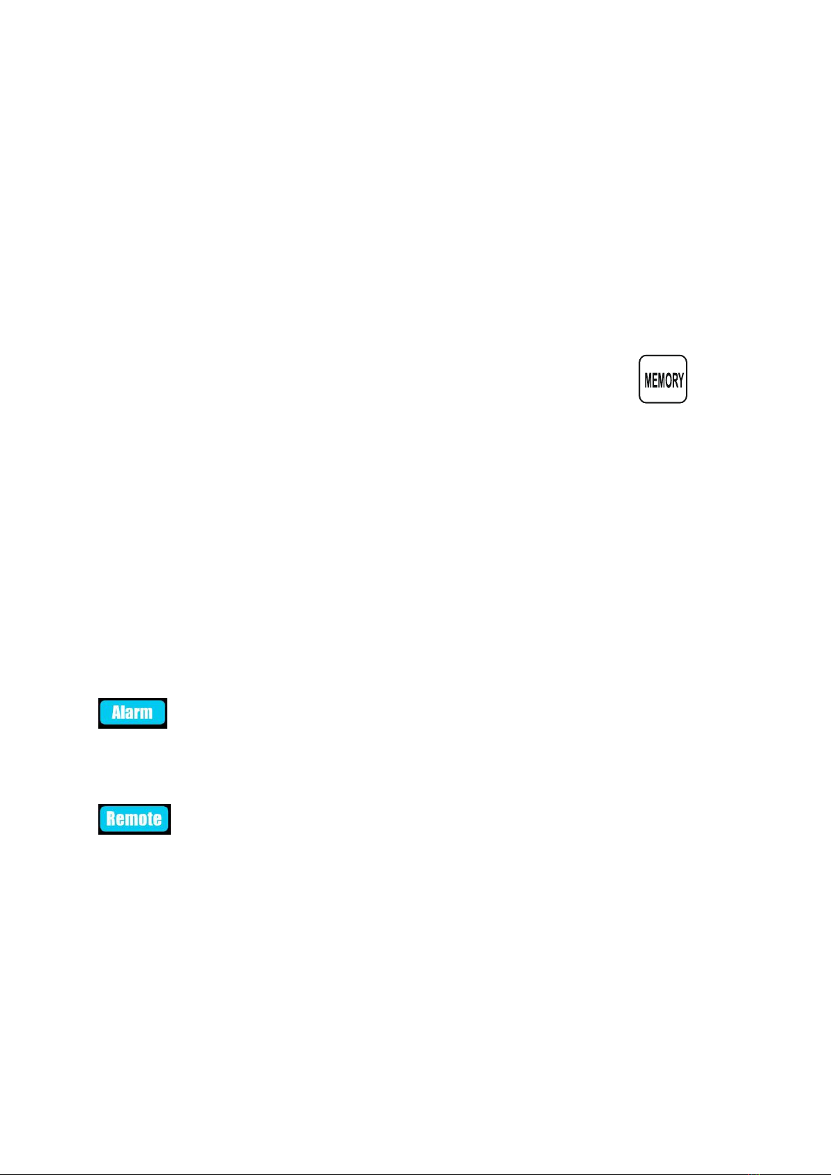
G – Settings memory
The device has the memory of the last setting, i.e. after it has been turned off and on again, the last
set parameters are restored. The user can save a total of 20 settings. 10 for each TIG and MMA
method. To recall a previously saved set of settings, press the button (G) until the appropriate set
number appears on the memory display (H).
To memorize the current settings, press and hold the button (G) for 2 seconds, the number on the
display (H) will be pulsing. Turning the knob (D) change set number. If you push again during
10s to save actually adjusted setting. If you not push (G) button again, you back to main menu.
If the device is switched off, when a set of parameters is loaded in the memory, after switching on
again, the last used set will be automatically loaded and its number will appear on the display. If no
parameter set is loaded in the memory and the device is switched off, after re-enabling, the last used
parameters will be restored and a dash will appear on the display (H).
H – Display of the parameter set memory
The display shows the number of the parameter set that has been loaded or where the current set will
be saved.
I – Welding parameters display
The display shows the parameters during their setting and during welding. The lighting of the
corresponding LED on the side of the display indicates the parameter unit.
Overheating protection - the power source is equipped with a thermal, automatic overload
switch. When the temperature of the welding machine is too high, the protection will disconnect the
welding current, the Alarm LED will light and the error code "E00" will appear on the display. After the
temperature has dropped, the breaker will be automatically reset.
A LED indicating that the device is in remote control mode. The LED will light up
automatically after connecting the remote-control plug to the socket.
6.2. PARAMETER SETTING
6.2.1 MMA method
In the MMA method, it is possible to adjust the welding current, the Hot Start, and the ARC FORCE
function. While adjusting the welding current, the diode lights up, and the Hot Start and ARC FORCE
function can be adjusted after the diode is lit.
HOT START & ARC FORCE - allows you to adjust the dynamics of the welding arc. The shortening of
the arc length is accompanied by an increase in the welding current, which results in stabilization of
the arc. Decreasing the value gives a soft curve and a smaller depth of penetration, while increasing
the value causes deeper penetration and the possibility of short arc welding. When the large value of

10
the ARC FORCE function is set, you can weld while maintaining an arc with a minimum length and
high melting rate of the electrode. The adjustment range: 0 ~ 100A
6.2.2 TIG method
Select welding TIG using the welding mode selection button (F). Select current (DC) or alternating
current (AC), enables or disables the pulse. Press the (B) button to select the waveform.
Set the welding parameters:
PRE-FLOW ( )- time from pressing the button in the grip handle and opening the gas valve
until the arc is ignited. Usually should be more than 0,5s.
Adjustment range: 0,1 ~ 15s
START CURRENT (Start Amp) - the current appearing in the circuit after pressing the button in the
grip handle. The higher the initial current, the easier it is to ignite the arc.
Adjustment range: 5 ~ Max Current
TIME OF CURRENT INCREASE (Up Slope) - welding current rise time from the initial current to the
set welding current value.
Adjustment range: 0 ~ 15s
WELDING CURRENT (Peak Amp) – main welding current
Adjustment range: 5 ~ Max Current
TIME OF SPOT WELDING (SPOT) – spot welding time
Adjustment range: 0,1 ~ 15s
PULSE WIDTH (pulse duty) - duration of the impulse, allows you to adjust the depth of the penetration.
The increase in width increases the depth of penetration, the reduction reduces the amount of heat
entering the material, reducing the risk of burning thinner sheets or smaller elements
Adjustment range: 10 ~ 90%
PULSE FREQUENCY - the frequency with which the value of the current pulse between the welding
current and the base current changes.
Adjustment range: 0,5 ~ 999Hz / suggest at 200Hz
BASE CURRENT (Base Amp) -the current responsible for maintaining the welding process, the lower
value of the current pulse. It makes it easier to control the amount of heat entering the material.
The base current adjustment is only possible during pulse welding
Adjustment range: 5 ~ Max Current
AC FREQUENCY -the function is useful when welding aluminum. The higher the frequency,
the better the weld quality and the better the arc focus

11
Adjustment range: 1 ~ 250 Hz/ suggest at 60Hz
AC BALANCE - The ratio of the duration of the positive to negative phase. The reduction of the
balance results in the introduction of more heat into the material, resulting in a narrower weld and
deeper penetration, and at the same time reduces the heat load of the tungsten electrode. Increasing
the balance results in the introduction of less heat into the material, resulting in better cleaning, a
broad joint and a shallower penetration, however, it significantly weighs the tungsten electrode.
Adjustment range: 15 ~ 50% / suggest 28%
TIME OF CURRENT DESCENT – (Down Slope) - time of transition current from main (current) to final
(I stop)
Adjustment range: 0 ~ 15s
FINAL CURRENT (Finish Amp) - current to fill the crater
Adjustment range: 5 ~ Max Current
POST GAS ( ) - time from quenching the arc to closing the gas valve to cover the solidifying weld
pool from the air and to cool the tungsten electrode. Too short time of outflow may result in oxidation
of the weld,
Adjustment range: 0,1 ~ 15s
7. WELDING
Welding with a coated electrode (MMA)
-Select the MMA method using the welding method selection button. In this mode it is possible to
adjust the welding current and adjust the ARC FORCE function. Adjusting the welding current is
possible directly after switching on the power supply. Turning the control knob will change the welding
current.
- Arc initiation when welding a coated electrode involves touching the electrode to the welded material,
short rubbing and detachment. In the case of arc initiation with electrodes, which after coating forms a
non-conductive slag, it is necessary to pre-clean the tip of the electrode by repeated impact against a
hard surface until metallic contact with the welded material.
Welding in shielded gas (TIG method) - The device is equipped with an ionizer that allows
contactless arc ignition. To ignite the arc in 2T mode, the electrode should be brought closer to the
welded material for a distance of 2 millimeters and press the button in the torch holder to activate the
ionizer. After correct arc initiation, carry out the welding with the button pressed. Releasing the button
on the handle causes the start of the current dropping phase and the end of the welding process. In
order to ignite the arc in 4T mode, the electrode should be brought closer to the material to a distance
of 2 millimeters and press the button on the torch handle to activate the ionizer. After correct arc
ignition, the button can be released and the welding can be carried out with the button released. To
stop welding, press and release the button on the handle again.
Welding in shielded gas (TIG LIFT) - To start the arc in the two-stroke mode, press the button in the
grip handle to activate the gas flow. touch the welding material with the electrode, shortly rub and tear
off. After correct arc initiation, carry out the welding with the button pressed. Releasing the button on
the handle causes the start of the current dropping phase and the end of the welding process.
To start the arc in the four-stroke mode, press the button in the grip handle to activate the gas flow.
touch the welding material with the electrode, shortly rub and tear off. After correct arc ignition, the

12
button can be released and the welding can be carried out with the button released. To stop welding,
press and release the button on the handle again.
Welding in 2T mode - TIG
0:Press and hold the handle button. The outflow of protective gas begins;
0~t1:Pre flow
t1~t2 : Arc ignition, welding current increases from the minimum value to the set welding current
value. If the pulsator is on, the current is modulated.
t2~t3:During welding, the handle button should remain pressed;
Note: If the pulsator is on, the welding current flashes, if the pulsator is turned off, the welding
current has a constant value.
t3:Release the torch button, the welding current begins to drop. If the pulsator is on, the falling
current is modulated;
t3~t4:Welding current falls to the minimum value, the arc is extinguished;
t4~t5:Post gas
t5:The solenoid valve closes the gas flow, completing welding.
Welding in 4T mode - TIG
0: Press and hold the handle button. The outflow of protective gas begins;
0~t1:pre flow

13
t1:Ignition of the arc, the starting current is set;
t2:Release the handle button, the current begins to rise to the set welding current value. If the
pulsator is on, the current is modulated
t2~t3: up slope
t3~t4:welding process
t4:Press the handle button. The welding current begins to drop to the value of the crater
current
t4~t5: down slope
t5~t6:end current
t6:Release the handle button. The arc is extinguished, shielding gas flows out;
t7:The solenoid valve closes the gas flow, completing welding.
Welding in SPOT mode - TIG
0:Press and hold the handle button. The outflow of protective gas begins;
0~t1:Pre flow
t1~t2 : Arc ignition, welding current increases from the minimum value to the set welding current
value,and the spot welding starts now. If the pulsator is on, the current is modulated.
t2~t3:During welding, the handle button should remain pressed;
Note: If the pulsator is on, the welding current flashes, if the pulsator is turned off, the welding
current has a constant value.
t3:It is time to finish spot welding , the welding current begins to drop. If the pulsator is on, the
falling current is modulated;
t3~t4:Welding current falls to the minimum value, the arc is extinguished;
t4~t5:Post gas
t5:The solenoid valve closes the gas flow, release the button, completing welding.
8. PROBLEM AND SOLUTION
In case of malfunction of the device, before sending the welder to the service, check the list of basic
failures and try to remove them yourself. Any repairs to the device may only be made after
disconnecting the plug from the mains socket.

14
SYMPTOMS
FIND SOLUTION
The control panel does not
light up, the fan does not
work, no output voltage
1. Make sure that the switch is in the ON position
2. Check the protection and voltage in the network
3. Remove the housing and check the connection of all electrical plugs
inside the device
The control panel is on, the
fan is not working, no output
voltage.
1. Check whether the device has been connected to a higher voltage
network. If so, connect to the 230V grid and turn it on again
2. The power supply voltage is unstable and causes the overvoltage
protection to be activated. Switch the device off for 2-3 minutes and switch it
on again
3. The short-term switching on and off of the switch has triggered the
overvoltage protection. Switch the device off for 2-3 minutes and switch it on
again
4. There was another damage requiring repair by an authorized service
center
The control panel is on, the
fan is running, problems with
arc ignition
Check the TIG torch, replace the consumables if they are worn
The control panel is on, the
fan is running, problems with
arc ignition
1. Check the terminals and the correct electrical conductivity of the electrode
and ground wires
2. Check the connection of the TIG torch to the device, make sure that the
pins in the socket are not broken or jammed.
3. Unscrew the handle of the TIG torch and check that the switch in the
holder is working
The control panel is on, the
fan is working, the O.C diode
is on. "E00" message on the
display
The device has been overheated. Wait a few minutes. After the diode goes
out, continue welding.
Unsatisfactory weld quality
during MMA welding, the
electrode is bonded to the
material being welded
1. Check the polarity of the welding cable connections
2. Check that the electrode is not wet. Replace the electrode.
3. The welder is powered from a generator set or a long extension with too
small a cable cross section. Connect the device directly to the mains
Unsatisfactory weld quality
for TIG welding
1. Replace consumable parts. Change the tungsten electrode or gas cylinder
with higher quality materials
2. Check that shielding gas flows with the appropriate intensity
3. Check the gas supply hose, improve the hose and couplings connection
and the condition of quick couplers
4. Check reducer.
List of error codes:
E00
Overheating of the device or incorrect welding current parameters
9. OPERATING INSTRUCTIONS
Operation of the device should take place in an atmosphere free from corrosive ingredients and high
levels of dust. Do not place the device in dusty places, near grinders, etc. Dust and contamination with
metal filings of control boards, wires and connections inside the device can lead to an electrical short
circuit and consequent damage to the welder.
15
Avoid operation in environments with high humidity, in particular in situations of dew on metal
elements.
In the case of dew on metal elements, for example, after entering a cool device into a warm room, wait
until the dew disappears. It is recommended that when the machine is used outdoors, it should be
placed under the roof in order to protect it from adverse weather conditions.
10. MAINTENANCE INSTRUCTIONS
As part of everyday service, keep the welder clean, check the condition of external connections and
the condition of wires and electric cables.
Replace consumable parts regularly.
Periodically clean the device inside by blowing with compressed air to remove dust and metallic filings
from the control plates as well as wires and electrical connections.
At least once every six months a general review and condition of electrical connections should be
made, in particular:
- protection against electric shock
- insulation condition
- security system status
- correct operation of the cooling system
11.STORAGE AND TRANSPORT INSTRUCTIONS
The device should be stored at -10 ° C to + 40 ° C and relative humidity up to 80% free from corrosive
fumes and dust. The transport of packaged devices should take place in covered transport means.
During transport, the packed device should be secured against shifting and ensure their proper
position.
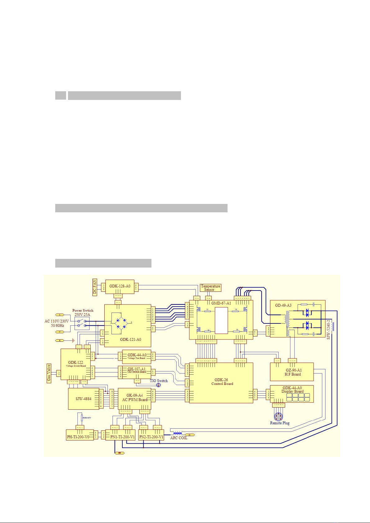
12.ELECTICAL DIAGRAM

16
IGBT Equipment Warranty
Welding Material Sales
Effective Jan 1, 2019
Limited Warranty
This warranty applies to the original purchaser and is subject to the terms and conditions
listed below.
This Limited Warranty is for new equipment sold after the above date, providing coverage for
defects in material and workmanship at the time it is shipped from the factory.
Limited to the warranty periods listed below, Welding Material Sales will repair or replace the
item under warranty that fails due to defects in material and workmanship. Welding Material
Sales, Inc. must be notified within 30 days of the failure, so as to provide instructions on how
to proceed with the repair of your welder and warranty claim processing. Warranty period
begins at the time the welder is purchased from an authorized Welding Material Sales, Inc.
distributor and/or retailer. Proof of purchase will be required for Welding Material Sales to
proceed with any and all warranty claims, no exceptions.
Warranty Periods
Limited Warranty is divided into two categories: No warranty and 1 year.
No Warranty
Normal wear items including but not limited to MIG gun parts (contact tips, nozzle, adapter,
liner), TIG torch parts (collet, cup, back cap, torch body) drive roll, contactor, and electrode
holder are not covered under warranty.
1 Year
Solenoid valve, PC board, controls, gas valve, drive motor, and drive system. Parts and labor
performed by authorized repair center with original equipment repair parts. Call 888-905-
6737 for a repair center near you.
Table of contents
Other Blue Demon Welding System manuals


