Blue Demon IGBT Series User manual

OWNER'S MANUAL
THE IGBT SERIES OF MIG/MAG
BLUE DEMON BLUEARC 140MSI

1
CONTENTS
- 1.Safety……………………..………………..…………………………….…..……....…………………………………………………….
3
- 2.General Description……...………......……...…………………….………...……….....………………………………………..
4
-3.Main Parameter…….……...…...........…….....………………………………….…..……….……………………………………
6
- 4.Structure of welder…….……...…...........………………………..…………….…..……….……………………………………
7
- 5.Installation ……………………………………………………………………………………………………………………………..…
9
- 6.Welding settings quick reference chart……………………………………………………………………………………….
12
- 7.Range of welding current and voltage in CO2 welding...……….……………………………………………………
17
- 8.Welding parameters table.......…....................……………………….………..……………………………………………
18
- 9.Caution……….....................…………………………………………...………………. .....…......................................
20
- 10. Maintenance….………………………………………….……………….….……....….……………………………………………
21
- 11. Daily checking……………………………………….….……....….………………………………………….……………………..
22
- 12. Connection diagram of the machine………………………………….….……....….…………………………………..
25
- 13. Explosion drawing…………………………..………………………………….….……....….…………………………………..
26
- 14. IGBT Equipment Warranty……………..………………………………….….……....….…………………………………..
27

2
This welding machine for industrial and professional use is in conformity with IEC974 International
Safety Standard.
We hereby state that we provide one year of warranty for this welding machine since the date of
purchase. See full warranty disclaimer on last page of user manual.
Please read and understand this instruction manual carefully before the installation and operation
of this machine.
The contents of this manual may be revised without prior notice. For most current version of
manual visit www.bluedemonwelding.com
This instruction manual is issued in June 2020.

3
1.SAFETY
Welding and cutting is dangerous to the operator, people in or near the working area, and the surroundings
if the machine is not correctly operated. Therefore, the performance of welding/cutting must only be under
the strict and comprehensive observance of all relevant safety regulations. Please read and understand this
instruction manual carefully before installation and operation.
·Do not switch function modes while machine is in use. This will damage
machine and void warranty.
·Disconnect and remove the electrode-holder cable when not in MMA (SMAW)
mode.
·A safety switch is necessary to prevent the machine from electric leakage.
·Use only welding tools and consumables of high quality.
·Operators should be qualified.
Electric shock: It can be fatal!
·Connect the earth cable according to standard and local regulation.
·Avoid all contact with live electrical parts of the welding circuit, electrodes and
wires with bare hands. It is necessary for the operator to wear dry welding gloves
while he/she performs the welding task.
·The operator should keep the working piece insulated from himself/herself.
Smoke and gas generated while welding or cutting can be harmful to people’s
health.
·Avoid breathing the smoke and gas generated while welding or cutting.
-Use fume extraction equipment if available.
·Keep the working area well ventilated.
Arc rays: harmful to people’s eyes and skin.
·Wear welding helmet, anti-radiation glass and work clothes while the welding
operation is performed.
·Measures also should be taken to protect people in or near the working area.
.
Fire hazard
·The welding spatter may cause fire, thus remove flammable material from the
work area.
·Have a fire extinguisher nearby and have a trained person ready to use it.
Noise: possibly harmful to peoples’ hearing.
·Noise is generated while welding/cutting, wear approved ear protection if noise
level is too high.
Machine fault:
·Consult this instruction manual.
·Contact your local dealer or supplier for further advice.
4
2.GENERAL DESCRIPTION
This welding machine is composed of an inverter MIG welder power supply with invariable voltage output
external characteristics manufactured with advanced IGBT inverter technology designed by the
manufacturer.
With high-power component IGBT, the inverter converts the DC voltage, which is rectified from input
50Hz/60Hz AC voltage, to high frequency 20KHz AC voltage; consequently, the voltage is transformed and
rectified. The features of this machine are as follows:
● IGBT inverter technology, current control, high quality, stable performance.
● Closed feedback circuit, invariable voltage output, great ability of balance voltage up to ±15%;
● Electron reactor control, stable welding arc, minimal spatter, deep molten pool, excellent weld bead
profile.
● Welding voltage can be preset, and the voltmeter displays the preset voltage value when not welding.
● Both welding current and welding voltage can be observed at the same time.
● Burn back time is adjustable.
● Slow wire feeding during arc starting. Reliable arc starting.
● Wire feeding is separate from the welding machine providing a wider welding operation range.
● Small-sized, light-weight, easy to operate, and economical.
Unpacking your machine
When unpacking inspect carefully for any damage that may have occurred during transit. Check carefully to
ensure all the contents on the list below have been received in good condition
Included items:
No.
Description
Qty.
Pic
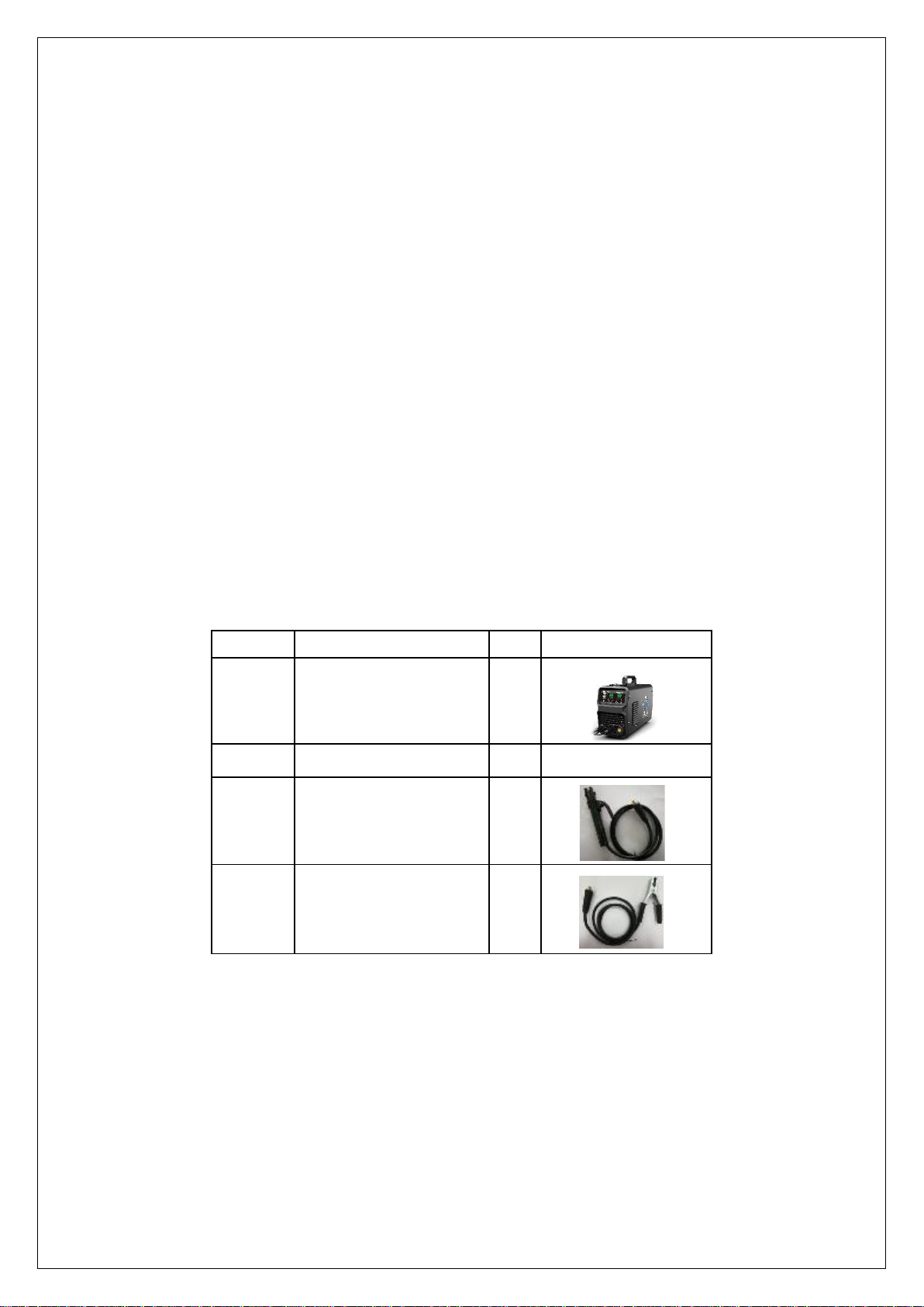
1
MIG Welder
1set
2
Operator’s Manual
1pc
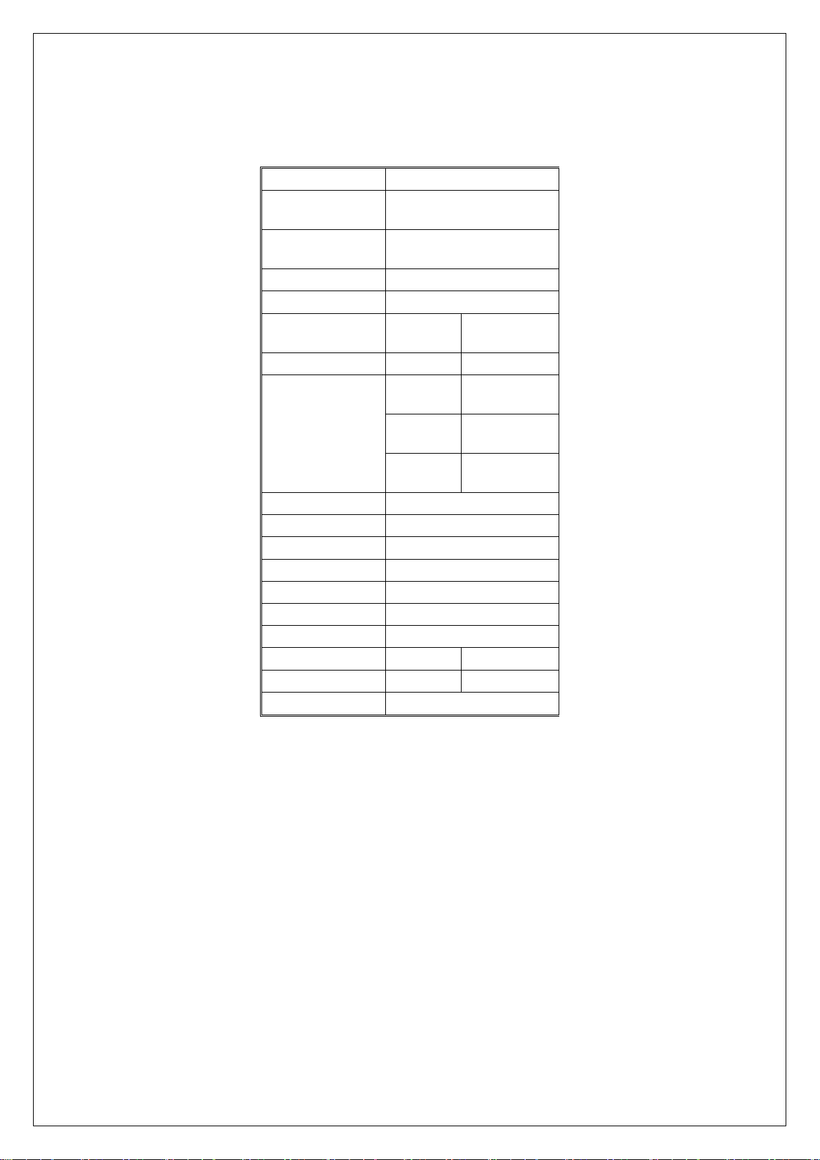
3
Electrode Holder
1pc
4
Earth Clamp
1pc
Operating environment
Adequate ventilation is required to provide proper cooling for the BLUEARC 140MSI. Ensure that the
machine is placed on a stable level surface where clean cool air can easily flow through the unit. The
BLUEARC 140MSI has electrical components and control circuit boards which will be damaged by excessive
dust and dirt, so a clean operating environment is essential.

5
Block Diagram
INPUT
CONTROL
6
3. MAIN PARAMETER
Main Parameter
Note : The welding duty cycle is the percentage of actual continuous welding time that can occur in a ten minute cycle. For
example: 15% at 200amps- this means the welder can weld continuously at 200 amps for 1.5 minutes and then the unit will
need to be rested for 8.5 minutes.
The duty cycle can be affected by the environment in which the welder is used. In areas with temperatures exceeding 40℃,
the duty cycle will be less than stated. In areas less than 40 ℃, higher duty cycles have been obtained
All tests on duty cycles have been carried out at 40℃ with a 50%. So in practical working conditions the duty cycles will be
much greater than those stated above.
MODEL
BLUEARC-140MSI
Power supply
voltage
120±10%
Rated input capacity
6
Frequency(inverter)
45
Rated input current
45\24.6
Output current
range
50-140
10-120
Function
MIG
MMA
Duty cycle (40℃
10min)
30% 140A
30% 120A
60% 108A
60% 92A
100% 76A
100%65A
No load voltage
51
Efficiency
80
Power factor
0.75
IP
21S
Insulation class
H
Cooling way
FAN & AIR
Dimension
430x150x290
Wire diameter
.023”-.035”
1/16”-3/32”
Electrode type
Fe & Al
6013,7018,etc.
Net weight
10

7
11
4. Structure of welder
1. Current adjustment
2. Voltage adjustment
3. Over temperature protection LED
4. Welding mode switch
5. Integrated MIG torch
6. Positive (+) Welding Output Terminal
7. Negative (-) Welding Output Terminal
8. Power switch
9. Power cable
10. Welding gas inlet
11. Hinge
1
2
3
4
5
6
7
8
9
10
12. MIG wire drive roller
13. MIG wire feeder
14. MIG wire spool shaft
12
13
14
8
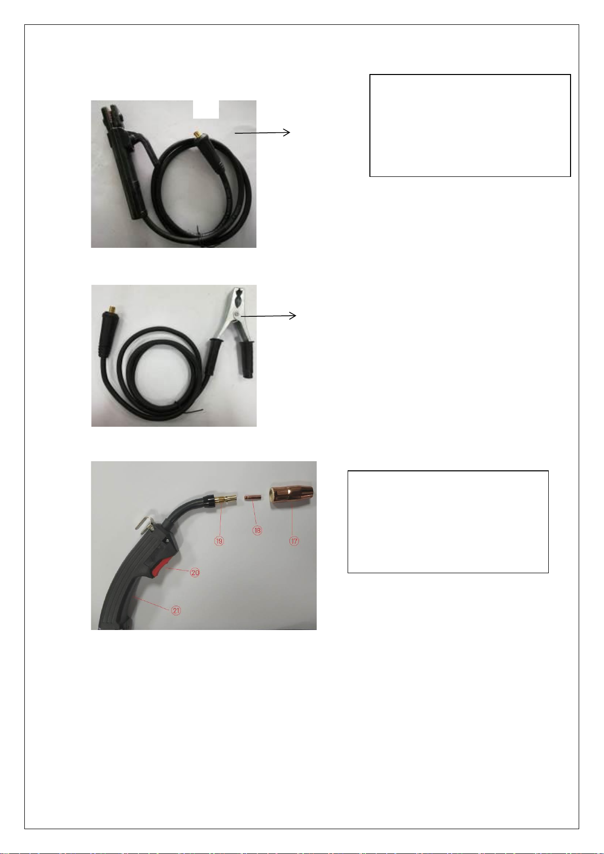
15. Electrode holder
16. Alligator clip (ground clamp)
15
16
17. Nozzle
18. Contact Tip
19. Tip Adapter
20. Trigger
21. Handle
9
5.INSTALLTION
5.1. MIG Welding Set Up & Operation
5.1.1 Fitting the spool
5.1.1.1 open the cover door for the wire feed compartment. Remove the wire spool retainer(14) by threading off counter-
clockwise.
5.1.1.2 fit either a 4in or 8in diameter wire spool to the spool holder, ensuring the end of the wires exits towards the wire
feeder from the bottom of the spool. Refit the wire spool retainer(14) and finger tighten.
5.1.1.3 set the spool brake tension by rotating the adjustment screw(14) using an Allen wrench. Clockwise to increase brake
tension, counter-clockwise to decrease brake tension. The spool brake tension should be set so that the spool can rotate
freely, but does not continue to rotate once the wire feed stops. This may need to be adjusted as the wire is used up and
the spool weight decreases.
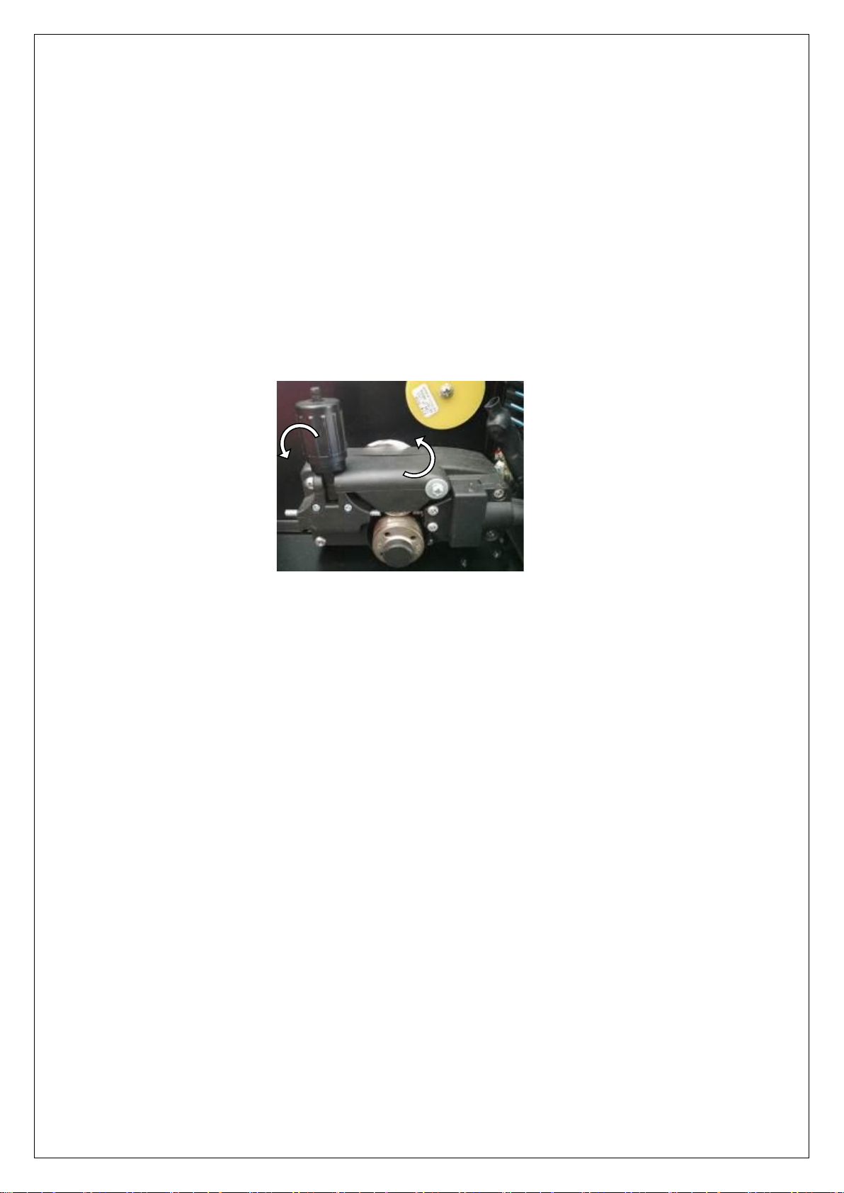
5.1.2 Loading wire feeder
5.1.2.1 release the wire feeder tension arm (shown below) by pivoting the wire feed tension adjuster(13) as pictured below
5.1.2.2 check the wire drive roller (12) groove matches the selected MIG wire type and size. The drive roller will have two
different sized grooves, the size of the groove in use is stamped on the side of the drive roller. For flux cored ‘soft’
wire ,such as that used in gasless MIG welding, the drive roller groove in knurled. For solid ‘hard’ MIG wire, the roller
groove has a ‘v’ shaped profile.
5.1.2.3 the drive roller(12) is removed by threading the drive roller retainer off in the counter-clockwise direction. Once
the correct drive roller profile is selected, re-fit the drive roller.
5.1.2.4 thread the MIG wire from the spool through the input guide tube, through the roller groove and into the outlet
guide tube
5.1.2.5 Replace the tension arm and the tension adjustment. Double check the wire has located correctly in the drive
roller groove.
5.1.2.6 Adjusting wire feed tension: this is accomplished by winding the knob on the wire tension adjustment arm.
Clockwise will increase tension, counter-clockwise will decrease tension. There is a numbered scale on the tensioner to
indicate the position. Ideal tension should be as little as possible, while maintaining a consistent wire feed with no drive
roll slippage. Check all other possible causes of slippage, such as; incorrect/ worn drive roller, worn/ damaged torch
consumables, blocked/ damaged torch feed liner, before increasing feed tension.
Warning! - Before changing the feed roller or wire spool, ensure that the mains power is switched off
Warning! - The use of excessive feed tension will cause rapid and premature wear of the drive roller, the
support bearing and the drive motor.

10
1)
Connection of Shield Gas
Connect inert gas hoes to gas inlet (10) with standard hose fitting and
tighten securely. If using a hose without a fitting, secure with hose
clamp. The supply of your inert shielding gas should include the gas
tank (aka bottle), regulator, and gas hose.
Please note:
1) Leakage of shielding gas affects the performance of arc welding.
2) Avoid the sunshine on the gas cylinder to eliminate the possible
explosion of gas cylinder due to the increasing pressure of gas
resulted from the heat.
3) Do not store your gas cylinder horizontally. Always secure your
gas cylinder to avoid tipping or falling over.
4) Ensure no person is up against the regulator, before the gas
release or shut the gas output.
5) The gas output volume meter (regulator) should be installed
vertically to ensure the precise measuring.
6) Before the installation of gas regulator, release and shut the gas
for several time in order to remove the possible dust on the sieve
to avail the gas output.

11
5.1.5 Controls for MIG welding
1 Current adjustment
2 Voltage adjustment
3 Welding mode switch
4 VRD = Voltage Reduction Device indicator light safety feature to reduce OCV for improper MMA connection to operator.
5 MMA –SMAW mode
6 SYN-synergize voltage and ampere automatically
7 MANUAL-manually adjust voltage and ampere in GMAW/FCAW mode
8 Temperature overload indicator light , after cooling down, machine can work again.
Note: this MIG welding machine MIG welding can be both synergic and separate, select the wire feed speed the voltage
parameter will be matched automatically.
Please select the wire diameter according to the wire you use.
Voltage refine initialization value is 0, refine the voltage by ±1V according to different kinds of gas.
2
4
1
3
5
6
7
8
12
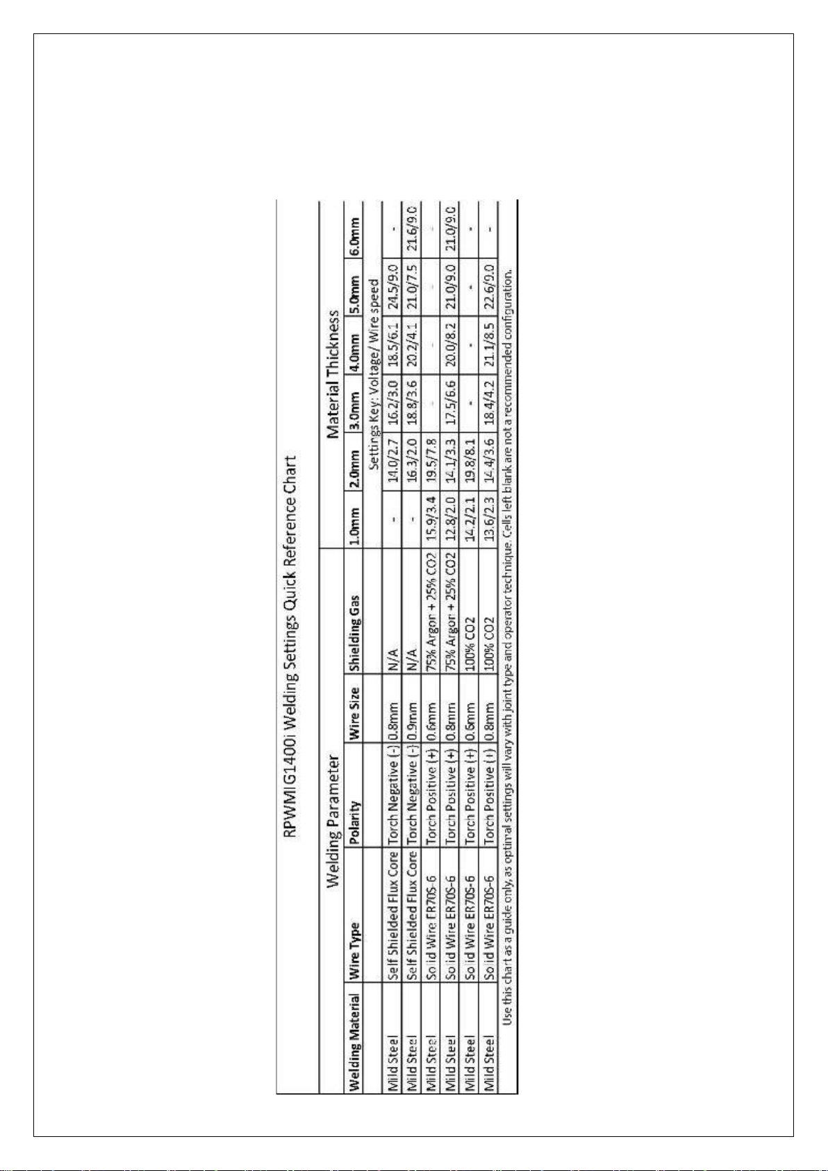
6.Welding settings quick reference chart
13
Basic welding guide
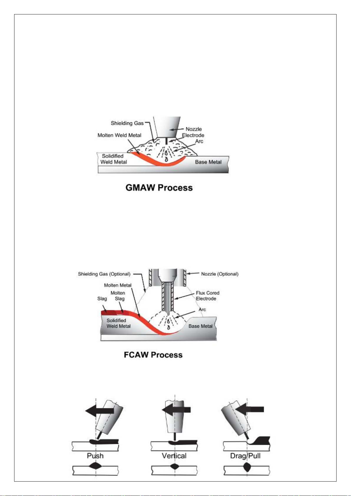
MIG (GMAW/FCAW) Basic Welding Technique
Two different welding processes are covered in this section (GMAW and FCAW), with the intention providing the very basic
concepts in using the MIG mode of welding, where a welding gun is hand held, and the electrode (welding wire) is fed into
a weld puddle, and the arc is shielded by an inert welding grade shielding gas or inert welding grade shielding gas mixture.
GAS METAL ARC WELDING (GMAW): This process, also known as MIG welding, CO2 welding, Micro Wire Welding, short arc
welding, dip transfer welding, wire welding etc., is an electric arc welding process which fuses together the parts to be
welded by heating them with an arc between a solid continuous, consumable electrode and the work. Shielding is obtained
from an externally supplied welding grade shielding gas or welding grade shielding gas mixture. The process is normally
applied semi automatically, however the and fairly thick steels, and some non-ferrous metals in all positions.
FLUX CORED ARC WELDING (FCAW): This is an electric arc welding process which fuses together the parts to be welded by
heating them with wan arc between a continuous flux filled electrode wire and the work. Shielding is obtained through
decomposition of the flux within the tubular wire. Additional shielding may or may not be obtained from an externally
supplied gas or gas mixture. The process is normally applied semi automatically; however the process may be applied
automatically or by machine. It is commonly used to weld large diameter electrodes in the flat and horizontal position and
small electrode diameters in all positions. The process is used to a lesser degree for welding stainless steel and for overlay
work.
Position of MIG Torch
The angle of MIG torch to the weld has an effect on the width of the weld
14
The welding gun should be held at an angle to the weld joint. (See Secondary Adjustment Variables below) Hold the gun so
that the welding seam is viewed at all times. Always wear the welding helmet with proper filter lenses and use the proper
safety equipment.
CAUTION
Do not pull the welding gun back when the arc is established. This will create excessive wire extension (stick-out) and make
a very poor weld.
The electrode wire is not energized until the gun trigger switch is depressed. The wire may therefore be placed on the seam
or joint prior to lowering the helmet.
Distance from the MIG Torch Nozzle to the Work Piece
The electrode wire stick out from the MIG Torch nozzle should be between 10mm to 20.0mm. This distance may vary
depending on the type of joint that is being welded
Travel Speed
The speed at which the molten pool travels influences the width of the weld and penetration of the welding run
MIG Welding (GMAW) Variables
Most of the welding done by all processes is on carbon steel. The items below describe the welding.
variables in short-arc welding of 24gauge (0.024”, 0.6mm) to ¼” (6.4mm) mild sheet or plate. The applied techniques and
end results in the GMAW process are controlled by these variables.
Preselected Variables
Preselected variables depend upon the type of material being welded, the thickness of the material, the welding position,
the deposition rate and the mechanical properties. These variables are:
Type of electrode wire
Size of electrode wire
Type of gas (not applicable to self-shielding wires FCAW)
Gas flow rate (not applicable to self-shielding wires FCAW)

15
Primary Adjustable Variables
These control the process after preselected variables have been found. They control the penetration, bead width, bead
height, arc stability, deposition rate and weld soundness. They are:
Arc Voltage
Welding current (wire feed speed)
Travel speed
Secondary Adjustable Variables
These variables cause changes in primary adjustable variables which in turn cause the desired change in the bead
formation. They are:
1.Stick-out (distance between the end of the contact tube (tip) and the end of the electrode wire). Maintain at about 10mm
stick-out
2. Wire Feed Speed. Increase in wire feed speed increases weld current, Decrease in wire feed speed decreases weld current
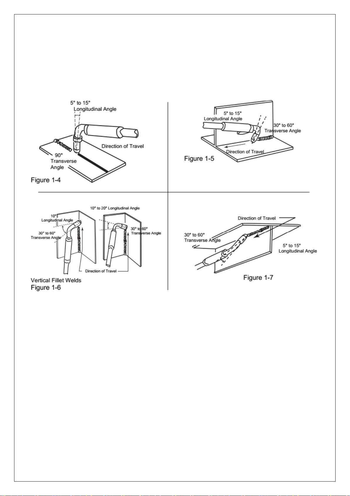
3. Nozzle Angle. This refers to the position of the welding gun in relation to the joint. The transverse angle is usually one half
the included angle between plates forming the joint. The longitudinal angle is the angle between the center line of the
welding gun and a line perpendicular to the axis of the weld. The longitudinal angle is generally called the Nozzle Angle and
can be either trailing (pulling) or leading
(pushing). Whether the operator is left handed or right handed has to be considered to realize the effects
of each angle in relation to the direction of travel.
Establishing the Arc and Making Weld Beads
Before attempting to weld on a finished piece of work, it is recommended that practice welds be made on a sample
metal of the same material as that of the finished piece
The easiest welding procedure for the beginner to experiment with MIG welding is the flat position. The equipment is
capable of flat, vertical and overhead positions.

16
For practicing MIG welding, secure some pieces of 16 or 18 gauge (0.06” 1.5mm or 0.08” 2.0mm) mild steel plate 6” x 6”
(150 x 150mm). Use 0.030” (0.8mm) flux cored gasless wire or a solid wire with shielding gas
Setting of the Power Source
Power source and Wire-`feeder setting requires some practice by the operator, as the welding plant has two control settings
that have to balance. These are the Wirespeed control and the welding Voltage Control. The welding current is determined
by the Wirespeed control, the current will increase with increase Wirespeed, resulting in a shorter arc. Less wire speed will
reduce the current and lengthen the Increasing the welding voltage hardly alters the current level, but lengthens the arc. By
decreasing voltage, a shorter arc is obtained with a little change in current level.
When changing to a different electrode wire diameter, different control settings are required. A thinner electrode wire needs
more Wire-speed to achieve the same current level
A satisfactory weld cannot be obtained if the Wirespeed and Voltage settings are not adjusted to suit the electrode wire
diameter and the dimensions of the work piece.
If the Wirespeed is too high for the welding voltage, “stubbing” will occur as the wire dips into the molten pool and does
not melt. Welding in these conditions normally produces a poor weld due to lack of fusion. If, however, the welding voltage
is too high, large drops will form on the end of the wire, causing spatter. The correct setting of voltage and Wirespeed can
be seen in the shape of the weld deposit and heard by a smooth regular arc sound. Refer to the Weld Guide located on the
inside of the wirefeed compartment door for setup information.
Electrode Wire Size Selection
The choice of Electrode wire size and shielding gas used depends on the following
Thickness of the metal to be welded
Capacity of the wire feed unit and Power Source
The amount of penetration required
The deposition rate required
The bead profile desired
The position of welding
Cost of the wire

17
7.Range of welding current and voltage in CO2welding
-The option of the welding speed
The welding quality and productivity should be taken into consideration for the option of welding speed. In case that the
welding speed increases, it weakens the protection efficiency and speeds up the cooling process. As a consequence, it is
not optimal for the seaming. In the event that the speed is too slow, the work piece will be easily damaged, and the seaming
is not ideal. In practical operation, the welding speed should not exceed 1m/min.
-The length of wire stretching out
The length of wire stretching out the nozzle should be appropriate. The increase of the length of wire stretching out of the
nozzle can improve the productivity, but if it is too long, excessive spatter will occur in the welding process. Generally, the
length of wire stretching out the nozzle should be 10 times as the welding wire diameter.
-The setting of the C02flow volume
The protection efficiency is the primary consideration. Besides, inner-angle welding has better protection efficiency than
external-angel welding. For the main parameter, refer to the following figure.
Option of C02 flow volume
Welding mode
Thin wire C02 welding
Thick wire C02welding
Thick wire, big current
C02welding
C02(L/min)
5~15
15~25
25~50
Wireφ(in)
Short circuit transition
Granular transition
Current(A)
Voltage (V)
Current(A)
Voltage (V)
0.023
40~70
17~19
160~400
25~38
0.030
60~100
18~19
200~500
26~40
0.035
80~120
18~21
200~600
27~40

18
8.WELDING PARAMETERS TABLE
The option of the welding current and welding voltage directly influences the welding stability, welding quality and
productivity. In order to obtain the good welding quality, the welding current and welding voltage should be set optimally.
Generally, the setting of weld condition should be according to the welding diameter and the melting form as well as the
production requirement.
The following parameter is available for reference.
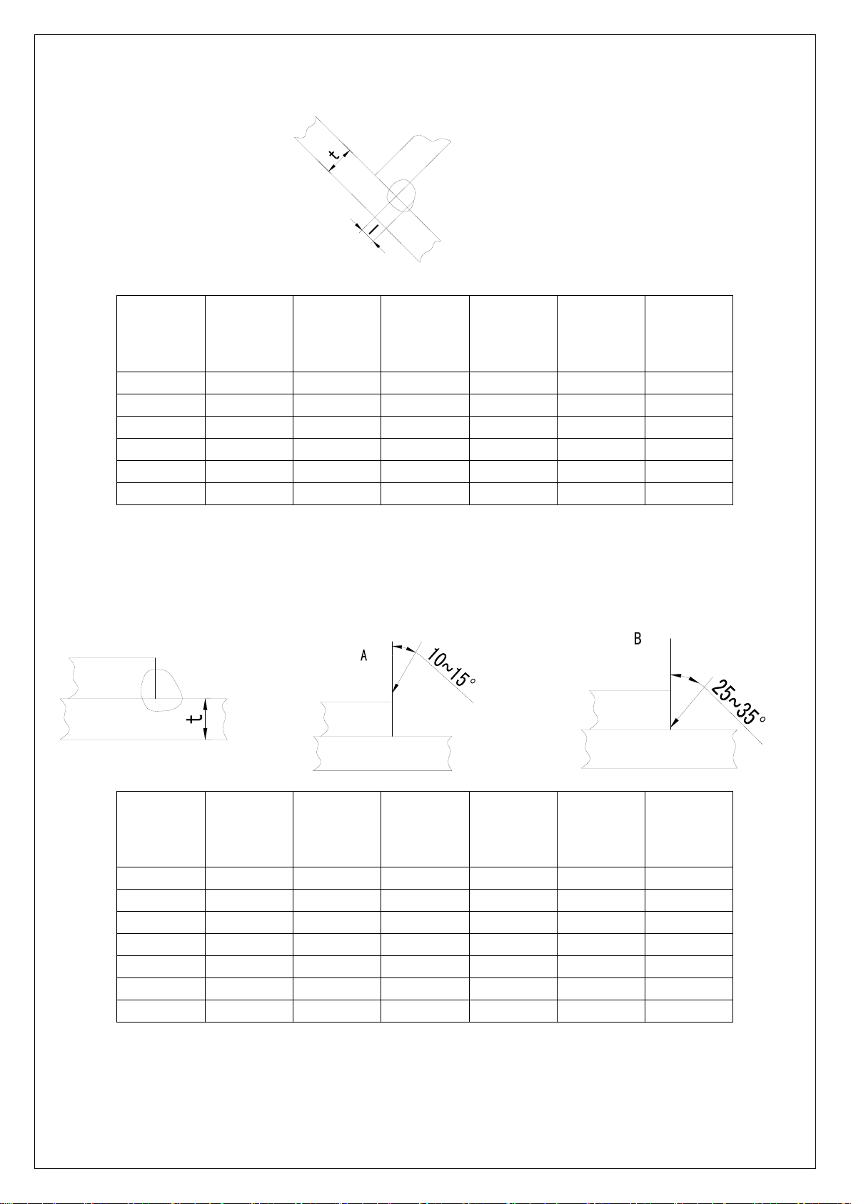
Parameter for butt-welding (Please refer to the following figure.)
Plate
thickness
t(mm)
Gap
g(mm)
Wire
φ(mm)
Welding
current
(A)
Welding
voltage
(V)
Welding
speed
(cm/min
)
Gas volume
(L/min)
0.8
0
0.8~0.9
60~70
16~16.5
50~60
10
1.0
0
0.8~0.9
75~85
17~17.5
50~60
10~15
1.2
0
1.0
70~80
17~18
45~55
10
1.6
0
1.0
80~100
18~19
45~55
10~15
2.0
0~0.5
1.0
100~110
19~20
40~55
10~15
2.3
0.5~1.0
1.0 or 1.2
110~130
19~20
50~55
10~15
3.2
1.0~1.2
1.0 or 1.2
130~150
19~21
40~50
10~15
4.5
1.2~1.5
1.2
150~170
21~23
40~50
10~15
Parameter for flat fillet welding (Please refer to the following figure.)
Plate
thickness
t(mm)
Corn size
I (mm)
Wire
φ(mm)
Welding
current
(A)
Welding
voltage
(V)
Welding
speed
(cm/min
)
Gas volume
(L/min)
1.0
2.5~3.0
0.8~0.9
70~80
17~18
50~60
10~15
1.2
2.5~3.0
1.0
70~100
18~19
50~60
10~15
1.6
2.5~3.0
1.0 ~ 1.2
90~120
18~20
50~60
10~15
2.0
3.0~3.5
1.0 ~ 1.2
100~130
19~20
50~60
10~20
2.3
2.5~3.0
1.0 ~ 1.2
120~140
19~21
50~60
10~20
3.2
3.0~4.0
1.0 ~ 1.2
130~170
19~21
45~55
10~20
4.5
4.0~4.5
1.2
190~230
22~24
45~55
10~20
19
Parameter for fillet welding in the vertical position (Please refer to the following figure.)
Plate
thickness
t(mm)
Corn size
I (mm)
Wire
φ(mm)
Welding
current
(A)
Welding
voltage
(V)
Welding
speed
(cm/min
)
Gas volume
(L/min)
1.2
2.5~3.0
1.0
70~100
18~19
50~60
10~15
1.6
2.5~3.0
1.0 ~ 1.2
90~120
18~20
50~60
10~15
2.0
3.0~3.5
1.0 ~ 1.2
100~130
19~20
50~60
10~20
2.3
3.0~3.5
1.0 ~ 1.2
120~140
19~21
50~60
10~20
3.2
3.0~4.0
1.0 ~ 1.2
130~170
22~22
45~55
10~20
4.5
4.0~4.5
1.2
200~250
23~26
45~55
10~20
Parameter for Lap Welding (Please refer to the following figure.)
Plate
thickness
t(mm)
Welding
position
Wire
φ(mm)
Welding
current
(A)
Welding
voltage
(V)
Welding
speed
(cm/min
)
Gas volume
(L/min)
0.8
A
0.8~0.9
60~70
16~17
40~45
10~15
1.2
A
1.0
80~100
18~19
45~55
10~15
1.6
A
1.0 ~ 1.2
100~120
18~20
45~55
10~15
2.0
A or B
1.0 ~ 1.2
100~130
18~20
45~55
15~20
2.3
B
1.0 ~ 1.2
120~140
19~21
45~50
15~20
3.2
B
1.0 ~ 1.2
130~160
19~22
45~50
15~20
4.5
B
1.2
150~200
21~24
40~45
15~20
This manual suits for next models
1
Table of contents
Other Blue Demon Welding System manuals


Popular Welding System manuals by other brands


Amada
Amada ML-2350AF Operation manual

HTP
HTP Invertig 160DC owner's manual

Rohr
Rohr HP-160L instructions

Chicago Electric
Chicago Electric 95136 Set up and operating instructions

Oerlikon
Oerlikon CITOCUT 10i Safety instruction for use and maintenance

Lincoln Electric
Lincoln Electric S350 CE Operator's manual


