Blue Giant BGL-22 User manual
OPERATOR’S MANUAL
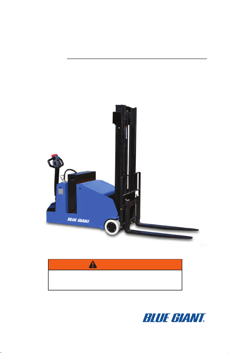
BGL-22 WALKIE COUNTERBALANCED
STACKER
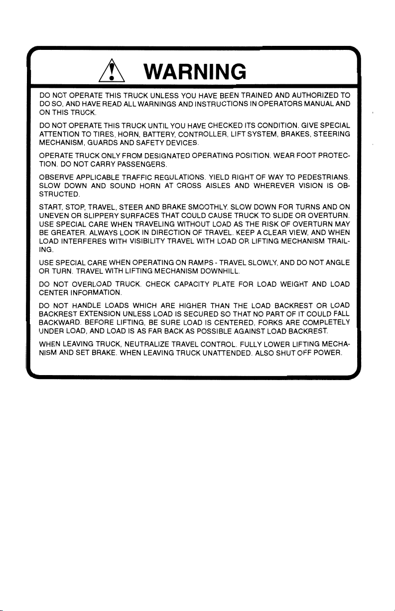
WARNING
Do not operate or service this product unless you have read and fully
understand the entire contents of this manual. Failure to do so may result in
property damage, bodily injury or death.
ISSUE DATE:MAY 5, 2020 REV.0 (PART # 038-926EO)

1
FOREWORD
As a lift truck operator, you are
responsible for a machine that is use-
ful, powerful, and can be hazardous if
not operated as described. Your
Blue Giant truck may weigh more than
some cars, depending on the
model. Observing and practicing
the safety warnings in this manual
cannot be overemphasized. Just
knowing the warnings, however, is
no substitute for common sense.
Using your common sense will, in
almost all cases, prevent accidents.
Think of the truck as your own. In
this way you will learn its
capabilities and limitations.
This manual is intended to remain
with the truck at all times as a handy
reference guide to operation. Detailed
maintenance procedures are found in
the parts and service manual for the
specific truck model, and are to be
performed only by a qualified techni-
cian. For further information on
obtaining a complete parts and ser-
vice manual, see page 21 of this man-
ual.
The operator who knows his truck will
learn to spot problems as they
develop. This is accomplished by per-
forming the Daily Checks and report-
ing any problems to the designated
authority.
TABLE OF CONTENTS
SAFETY SYMBOLS ..............................................................................................2
GENERAL DESCRIPTION ....................................................................................2
NAME PLATE AND WARNING DECAL................................................................2
LOAD CAPACITY ..................................................................................................4
BEFORE OPERATION ..........................................................................................5
Optional Features....................................................................................8
INSTRUMENTS AND CONTROLS .......................................................................7
Optional Features....................................................................................8
OPERATION ..........................................................................................................9
Forward and Reverse Travel and Speed Control..................................9
Steering ....................................................................................................9
Stopping.................................................................................................10
Parking ...................................................................................................10
Battery Charging ...................................................................................11
Load Handling .......................................................................................11
Moving a Disabled Truck ......................................................................11
NOTICE - OBTAINING A PARTS AND SERVICE MANUAL ..............................21

2
SAFETY SYMBOLS
WARNING and CAUTIONS are both signal words intended to alert the viewer to
the existence and relative degree of a hazard. They are both preceded by a safety
alert symbol consisting of an exclamation mark enclosed by a triangle.
A Warning indicates a hazard which could result in injury or death if proper pre-
cautions are not taken.
A Caution indicates a reminder of routine safety practices.
A prohibition slash (circle with diagonal slash through it) indicates a procedure or
action that should not be performed under any circumstances, as both personal
injury and/or damage to equipment will result.
GENERAL DESCRIPTION
Blue Giant Pallet trucks lift and
transport loads on rigid forks.
Control for steering, braking, forward
and reverse travel, horn, lift, lower and
speed control are all located on the
control handle.
Trucks in this series may vary in load
capacity, battery arrangement, and
instrumentation, depending on model
and options.
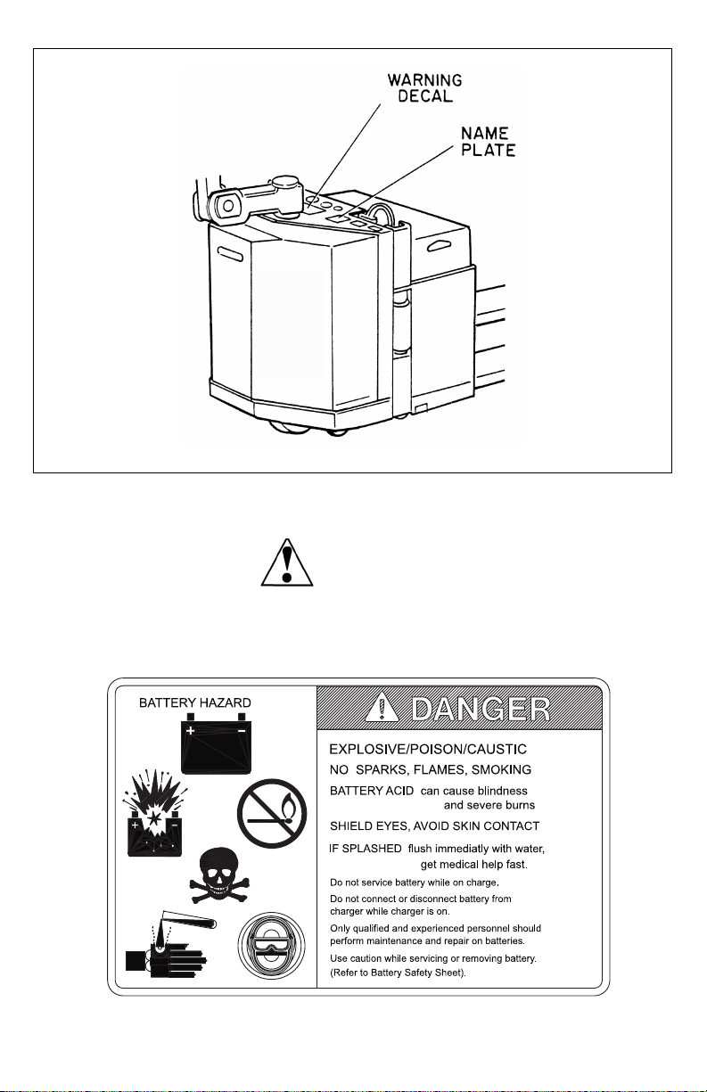
NAME PLATE AND WARNING DECAL
Name plate and warning decal loca-
tions may vary between models, but
they are always near the steering arm
within sight of the operator.
If the name plate or warning deal are
lost or damaged they should be
replaced immediately. Have your
supervisor or the designated authority
contact Blue Giant Authorized Dealer
for replacement.
The name plate shows the model
number; serial number; truck type;
battery type, voltage and minimum
weight. It also contains information on
the load capacity and load center. The
warning decal contains warnings
which also appear, with illustrations, in
the Operating Precautions section of
this manual.
3
Name Plate and Warning Decal Locations - Typical
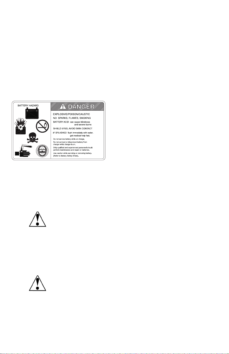
This truck is equipped with a battery. Read and heed the warning decal located
near the battery. An example is shown here:
WARNING:
R4906
4
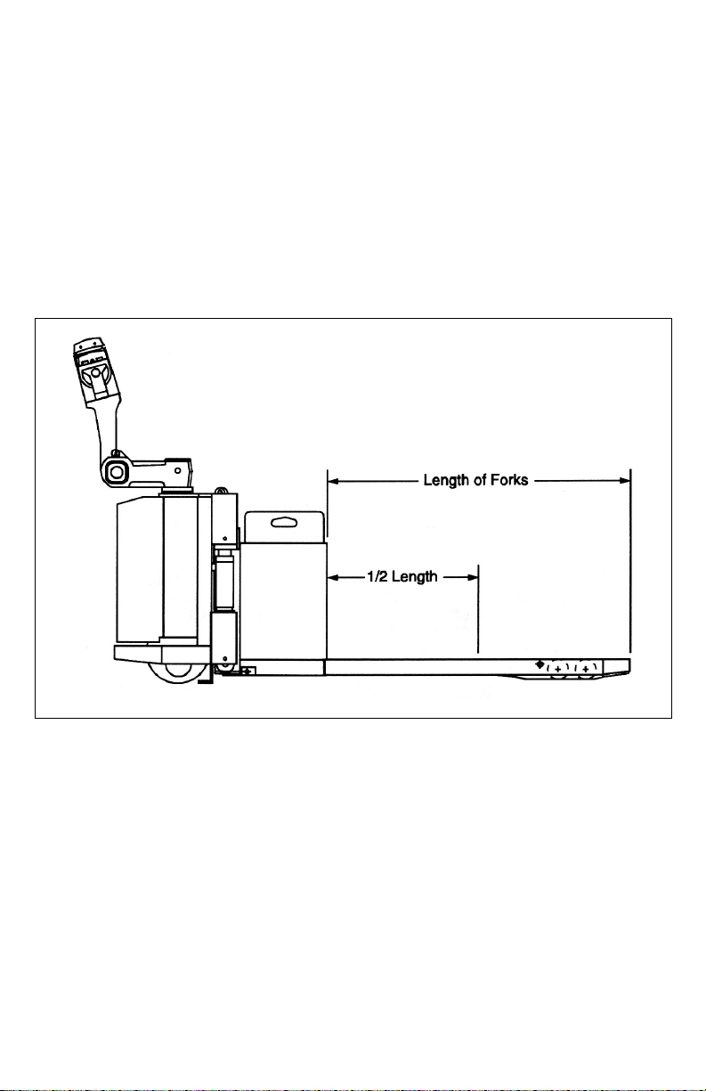
LOAD CAPACITY
Do not overload truck. Check capacity
plate for load weight and load center
information.
The load capacity depends on the
load center. The load maximum
capacity listed on the capacity plate
assumes a uniform load whose center
is at 1/2 the length of the fork and cen-
tered between the forks. The maxi-
mum load capacity is reduced when
the load center exceeds 1/2 the length
of the forks or is not centered between
the forks. The fork length and wheel-
base must be adequate for the skid or
bin to be handled.
Note that a truck undergoing speed
changes is less stable than a standing
truck. If you are not sure that the truck
can lift a certain load, consult your
supervisor or the designated authority.
Load Center
R5060

5
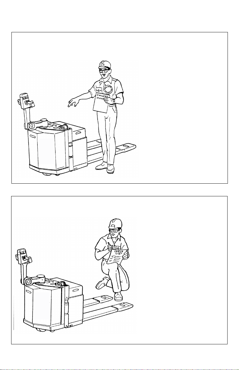
BEFORE OPERATION
The table on page 6 covers important
inspection points on trucks which
should be checked prior to operation.
Depending on use, some trucks may
require additional checks.
The illustration below shows a sample
format for a Operator Checklist, which
can be modified as necessary to fit
your operation.
Periodic maintenance of this
truck by a QUALIFIED TECH-
NICIAN is required.
A QUALIFIED SERVICE
TECHNICIAN should check the
truck monthly for proper lubrica-
tion, proper fluid levels, brake
maintenance, motor mainte-
nance and other areas speci-
fied in the parts and service
manual maintenance section.
If the truck is found to be unsafe
and in need of repair, or con-
tributes to an unsafe condition,
report it immediately to the des-
ignated authority. Do not oper-
ate it until it has been restored
to a safe operating condition.
Do not make any unauthorized
repairs or adjustments. All ser-
vice must be performed by a
qualified maintenance techni-
cian.
Sample of Operator Check List
WARNING:
WARNING:
WARNING:
R6235

6
Operator Checks
ITEM PROCEDURE
Transmission and hydraulic
systems
Check for signs of fluid leakage.
Forks Check for cracks and damage.
Guards and load backrest Check that safety guards are properly secured
and not damaged.
Safety signs Check that warning labels, nameplate, etc.,
are in good condition and legible.
Horn Check that horn sounds when operated.
Steering Check for binding or looseness in steering
arm when steering.
Travel controls Check that speed controls on control handle
operate in all speed ranges in forward and
reverse and that belly button switch functions.
Wheels Check drive wheel for cracks or damage.
Move truck to check load wheels for freedom
of rotation.
Hydraulic controls Check operation of lift and lower, and tilt to
their maximum positions.
Brakes Check that brakes actuate when steering arm
is raised to upright position, and when lowered
to horizontal position.
Deadman/Parking brake Check that steering arm raises to upright posi-
tion when released and brake applies.
Battery disconnect Check that battery can be disconnected and
reconnected. Check for connector damage.
High speed limit switch Allow for enough space to operate truck in
high speed. Disengage third speed using the
high speed cut-out switch, then test drive truck
to check if high speed is cut out.
7
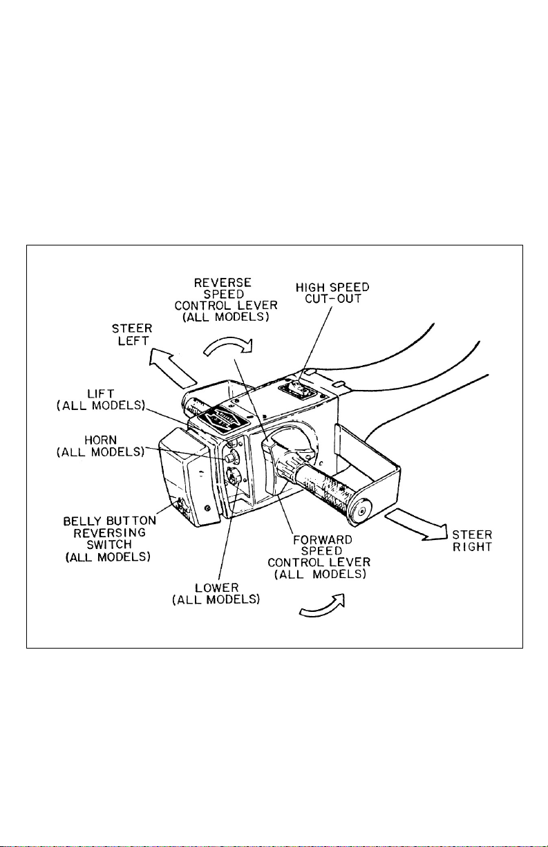
INSTRUMENTS AND CONTROLS
The steering arm and control handle
provide controls for steering, forward
and reverse speed control, braking,
raising and lowering the forks, and
horn. Control handles on some mod-
els have the high speed cut-out
switch. Control handles on all models
have a “belly-button” reversing switch
which reverses the direction of the
truck upon contact with the operator.
Detailed operating instructions are in
the Operation section of this manual.
A battery disconnect is mounted near
the steering arm. Pulling the discon-
nect removes all power from truck cir-
cuits in the event of an emergency.
Control Handle
R4070

8
Walkie/Rider Pallet Trucks have a
grab handle which also contains lift,
lower and horn controls.
Optional Features
The optional battery capacity indica-
tor, hour meter and keyswitch mount
on the panel near the control handle.
The battery capacity indicator moni-
tors the battery discharge rate to indi-
cate the remaining battery capacity.
The hour meter records the accumu-
lated hours that electrical energy is
being drawn from the battery to run
the pump and drive motors. The key-
switch provides added security to the
truck, preventing unauthorized per-
sonnel from operating the machine.
Grab Handle
R4907

9
OPERATION
Forward and Reverse Travel and
Speed Control
Control Handle
All directional and speed controls are
located on the control handle.
Forward and reverse are controlled by
rotating the speed control lever as
shown. The lever is spring loaded to
return to neutral when released. Fur-
ther rotation in either direction will
progress the truck from slow to maxi-
mum travel speed.
To change directions or to stop the
truck, rotate the speed control lever in
the opposite direction. The truck will
come to a stop and then, unless the
controls are returned to the center
neutral position, accelerate in the
opposite direction.
Steering
Moving the control handle (which con-
nects to the steering arm) right or left
will turn the truck right or left. When
maneuvering around corners, make
square turns and be sure there is
adequate clearance.
R4070
10
Stopping
Stop the truck as gradually as possi-
ble. Unnecessary rapid stopping could
be hazardous. Load could become
unstable.
There are four possible ways to stop
the truck:
1. Plugging: This electrical braking
function consists of rotating the
speed control lever in the oppo-
site direction of travel and then
releasing it when the truck stops.
Plugging is a convenient way to
stop the truck during normal
operation. If the control is not
released, the truck will accelerate
in the opposite direction.
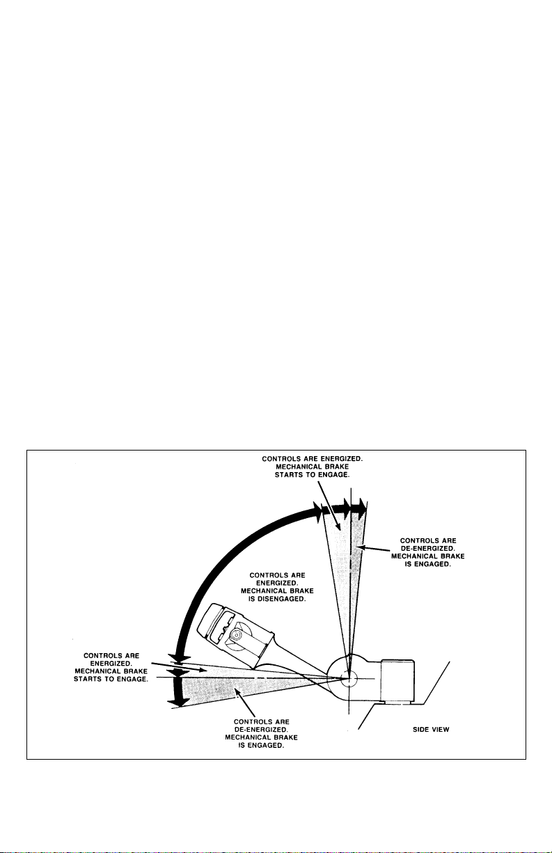
2. Steering arm in horizontal
position: Lowering the steering
arm to the horizontal position
applies brake pad pressure to the
brake disc. Lowering the steering
arm below the horizontal position
increases the braking force and
de-energizes the controls.
3. Steering arm in vertical posi-
tion: Raising the steering arm to
near vertical position applies
brake pad pressure to the brake
disc. Further vertical positioning
increases the braking force and
de-energizes the controls. This
position services as a parking
brake. As a safety precaution, the
steering arm is spring loaded to
return to the vertical position in
the event the driver releases the
control handle during operation.
This is known as deadman brak-
ing.
Parking
When parking the truck, do not
obstruct traffic lanes or aisles.
1. Park the truck in its designated
parking area.
Steering Arm Braking Positions
R3629
11
2. Raise the steering arm until verti-
cal to apply the parking brake.
3. Fully lower forks.
4. Turn keyswitch (if so equipped) to
off position. Remove key for
added security.
5. Pull out battery disconnect.
Battery Charging
Refer to DOC 245 for battery safety
and maintenance.
NOTE: Battery charging instructions
are contained in the service
manual.
Load Handling
Handle only loads arranged for
stability and always use cau-
tion. Raise and lower the load
smoothly to prevent the load
from falling.
Always be sure the load and
load center are within the
capacity of the truck. If in doubt
check the nameplate.
1. Approach the load slowly.
2. Move the truck slowly into posi-
tion so that the forks are centered
about the load.
3. Make sure the load is against the
backrest and then raise the forks
until the pallet clears the rack.
4. Lead the truck by the control han-
dle with the load trailing except
when in confined areas. Ramps
should be traveled with operator
uphill of truck when empty, or
operator downhill of truck with
load on forks.
5. Always look in the direction of
travel. Move slowly and check
clearances when approaching
obstructions.
6. Do not make sudden starts and
stops. Operate truck smoothly
and gradually.
7. Travel slowly and squarely
around corners. Remember that
the trailing load wheels do not fol-
low the turn path of the drive
wheel. Instead they tend to cut
the corner.
8. Line up the truck with the unload-
ing area.
9. Stop the truck and check the load
alignment with surrounding
objects.
10. Be careful not to damage or
move adjacent loads and objects.
11. Lower the forks until the load is
resting on its own.
12. Move the truck back until the
forks are clear of the pallet.
Moving a Disabled Truck
Do not attempt to move a disabled
truck; notify your supervisor or proper
authority.
WARNING:
WARNING:
12
The following operating instructions appear on the truck warning decal, which is
located near the steering arm.
R4071
Do not operate this truck unless you have
been trained and authorized to do so,
and have read and understand all warn-
ings and instructions contained in this
operator’s manual and on this truck.
R4072
Do not operate this truck until
you have checked its condition.
Give special attention to tires,
horn, battery, controller, lift sys-
tems, brakes, steering mecha-
nism, guards and safety
devices. If you have any ques-
tions, notify your supervisor or
proper authority.

13
R4073
Walkie Pallet Trucks: Operate
truck only from walking position.
R4905
Walkie/Rider Pallet Trucks:
Keep feet within limits of truck.

14
R4074
Wear foot protection and
keep feet clear of truck.
R4075
Do not carry passengers.
15
R4076
Observe applicable traffic regulations. Yield right-of-way to pedestrians.
Slow down and sound horn at cross aisles and wherever vision is
obstructed.
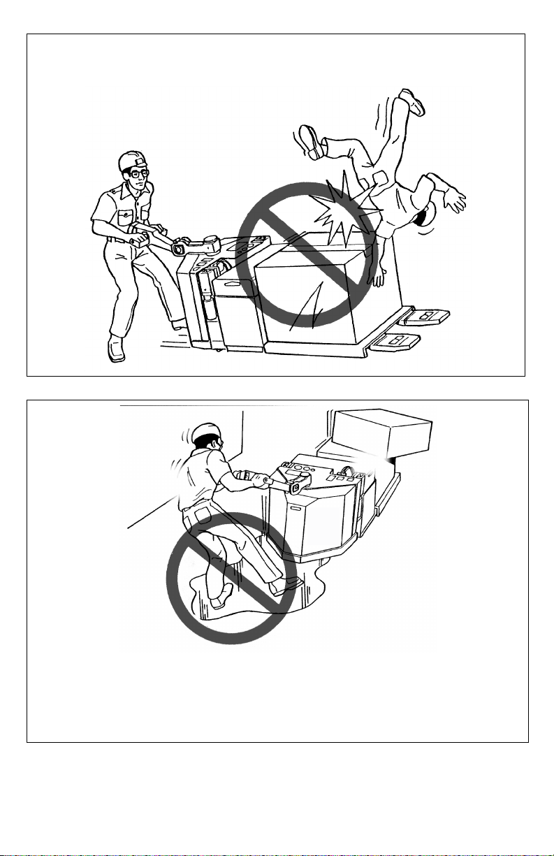
R4077
Start, stop, travel, steer and brake smoothly. Slow down for turns and on
uneven or slippery surfaces that could cause truck to slide or overturn. Use
special care when traveling without load as the risk of overturn may be
greater.

16
R4078
Always look in direction of travel. Keep a
clear view, and when load interferes with
visibility, travel with load or lifting mecha-
nism trailing (except when climbing
ramps.
R4079
Use special care when operating on ramps; travel slowly, and do not angle
or turn. Travel unloaded with lifting mechanism downhill, and travel loaded
with load uphill.

17
R4081
Do not handle loads which are higher
than load backrest or load backrest
extension unless load is secured so that
no part of it could fall backward.
R4082
Before lifting, be sure load is centered,
forks are completely under load, and
load is as far back as possible against
load backrest.

18
R4904
Keep hands out of lifting mechanism.
R4083
When leaving truck neutralize travel con-
trol. Fully lower lifting mechanism and
set brake. When leaving truck unat-
tended also shut off power.
Other manuals for BGL-22
1
Table of contents
Other Blue Giant Forklift manuals


