Blue Giant BGNR-30 User manual
OWNER’S MANUAL
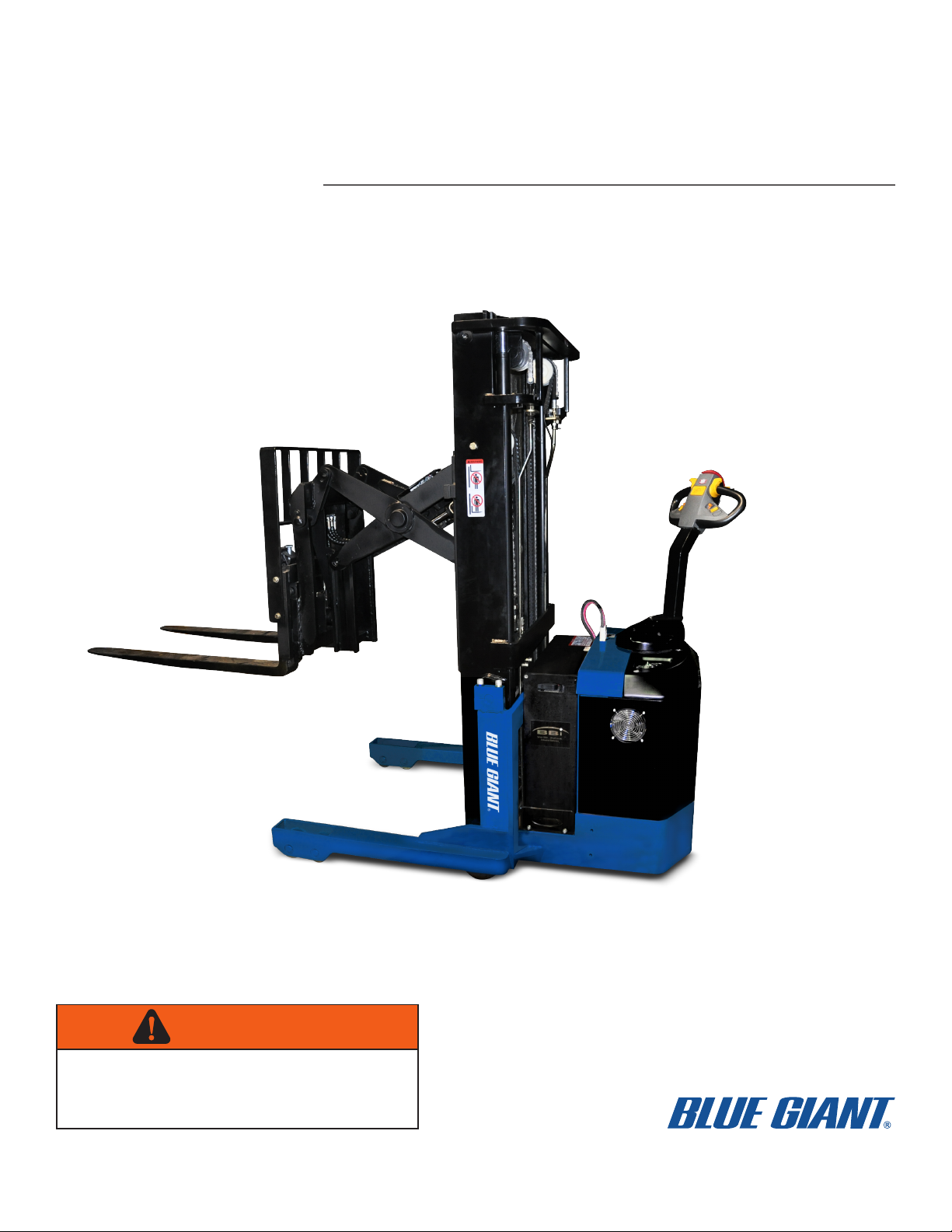
BGNR-30 POWERED WALKIE REACH STACKER
WARNING
Do not operate or service this product unless you have
read and fully understand the entire contents of this
manual. Failure to do so may result in property damage,
bodily injury or death.
ISSUE DATE: MAY 5, 2020 REV.0 (PART # 038-969E)
ACTUAL PRODUCT MAY NOT APPEAR EXACTLY AS SHOWN

BGNR-30 POWERED WALKIE REACH STACKER—OWNER’S MANUAL
2ISSUE DATE: MARCH 16, 2016 REV.0 (PART # 038-969E)
TO PREVENT SERIOUS RISK OF INJURY TO YOURSELF AND OTHERS OBSERVE THE FOLLOWING
SAFETY INSTRUCTIONS.
This Reach Truck may become hazardous if adequate maintenance is neglected. Therefore, adequate
maintenance facilities, trained personnel and procedures should be provided. Maintenance and inspection shall
be performed in conformance with the following practices:
1. A scheduled planned maintenance,lubrication and inspection system should be followed.
2. Only qualified and authorized personnel shall be permitted to maintain, repair, adjust, and inspect Reach
Truck.
3. Before leaving the Reach Truck:
– Do not park the Reach Truck on an incline.
– Fully lower the load forks.
– Press the emergency brake switch .
– Set the key switch to the “OFF” position and remove the key.
4. Before starting to operate Reach Truck:
– Be in operating position
– Place directional control in neutral
– Before operating Reach Truck, check functions of lift systems, directional control,speed
control,steering, warning devices and brakes.
5. Avoid fire hazards and have fire protection equipment present. Do not use open flame to check lever, or
for leakage of electrolyte and fluids or oil. Do not use open pans of fuel or flammable cleaning fluids for
cleaning parts.
6. Brakes,steering mechanisms, control mechanisms,guards and safety devices shall be inspected regularly
and maintained in legible condition.
7. Capacity, operation and maintenance instruction plates or decals shall be maintained in legible condition.
8. All parts of lift mechanisms shall be inspected to maintain them in safe operating condition.
9. All hydraulic systems shall be regularly inspected and maintained in conformance with good practice.
Cylinders, valves and other similar parts shall be checked to assure that “drift” has not developed to the
extent that it would create a hazard.
10. Reach Truck shall be kept in a clean condition to minimize fire hazards facilitate detection of loose or
detective parts.
11. Modifications and additions which affect capacity and safe Reach Truck operation shall not be performed
by the customer or user without manufacturers prior written approval. Capacity, operation and maintenance
plates or decals shall be changed accordingly.
WARNING

BGNR-30 POWERED WALKIE REACH STACKER—OWNER’S MANUAL
3ISSUE DATE: MARCH 16, 2016 REV.0 (PART # 038-969E)
TABLE OF CONTENTS
CORRECT USE AND APPLICATION 4
REACH TRUCK DESCRIPTION 5
APPLICATION 5
1.0 ABOUT THE BGNR-30 WALKIE REACH STACKER 6
1.1 OWNER’S PURCHASE RECORD 6
2.0 INTRODUCTION 6
2.1 WARRANTY INFORMATION 7
2.2 EXCLUSION OF LIABILITY 7
2.3 MANUFACTURER’S NOTE 7
2.4 SAFETY PROCEDURES 8
2.5 MOVING DANGER 8
2.6 APPLICATION ENVIRONMENT 8
2.7 LOADING SPECIFICATION 8
2.8 MAXIMUM INCLINE OR DECLINE GRADES 8
2.9 SAFETY WITH TALL LOADS 8
3.0 OPERATOR’S MANUAL SAFETY MESSAGE COLOR IDENTIFICATION 9
4.0 REACH TRUCK ASSEMBLIES 10
4.1 CONTROL HANDLE 11
4.1.1 KEY SWITCH 11
4.1.2 BATTERY DISCHARGE INDICATOR 12
4.1.3 STANDARD VERSION SPECIFICATIONS 12
4.1.4 PERFORMANCE DATA FOR STANDARD REACH TRUCKS 12
4.1.5 DIMENSIONS 13
4.2 IDENTIFICATION POINTS AND SERIAL PLATES 15
5.0 COMMISSIONING 16
5.1 USING THE REACH TRUCK FOR THE FIRST TIME 16
5.2 DURING BRAKE-IN 16
6.0 OPERATION 16
6.1 SAFETY REGULATIONS FOR THE OPERATION OF REACH TRUCKS 16
6.2 OPERATE AND RUN THE REACH TRUCK 17
6.2.1 PREPARING 17
6.2.2 TRAVEL, STEERING, BRAKING 17
6.2.3 LIFTING, TRANSPORTING AND DEPOSITING LOADS 18
6.2.4 PARKING THE REACH TRUCK SECURELY 19
7.0 BATTERY MAINTENANCE & CHARGING 20
7.1 SAFETY REGULATIONS FOR HANDLING ACID BATTERIES 20
7.2 BATTERY TYPE & DIMENSION 20

BGNR-30 POWERED WALKIE REACH STACKER—OWNER’S MANUAL
4ISSUE DATE: MARCH 16, 2016 REV.0 (PART # 038-969E)
CORRECT USE AND APPLICATION
The Reach Truck described in the present operator manual is an industrial Reach Truck designed for lifting and transporting load units.
It must be used, operated and serviced in accordance with the present instructions. Any other type of use is beyond the scope of
application and can result in damage to personnel, the Reach Truck or property. In particular, avoid overloading the Reach Truck with
loads which are too heavy or placed on one side. The data plate attached to the Reach Truck or the load diagram are binding for the
maximum load capacity. The Reach Truck must not be used in fire or explosion endangered areas, or areas threatened by corrosion or
excessive dust.
PROPRIETOR RESPONSIBILITIES
For the purposes of the present operator manual the “proprietor” is defined as any natural or legal person who either uses the Reach
Truck himself, or on whose behalf it is used. In special cases (e.g. leasing or renting) the proprietor is considered the person who, in
accordance with existing contractual agreements between the owner and user of the Reach Truck, is charged with operational duties.
The proprietor must ensure that the Reach Truck is used only for the purpose it is intended for and that danger to life and limb of the
user and third parties are excluded. Furthermore, accident prevention regulations, safety regulations and operating, servicing and repair
guidelines must be followed. The proprietor must ensure that all Reach Truck users have read and understood this operator manual.
Failure to comply with the operator manual shall invalidate the warranty. The same applies if improper work is carried out on the Reach
Truck by the customer or third parties without the permission of the manufacturer’s customer service department.
ADDING ACCESSORIES
The mounting or installation of additional equipment which affects or enhances the performance of the Reach Truck requires the written
permission of the manufacturer. Local authority approval may also need to be obtained. Local authority approval does not however
constitute the manufacturer’s approval.
TABLE OF CONTENTS CON’T.
7.3 CHARGING THE BATTERY 20
7.4 BATTERY REMOVAL AND INSTALLATION 21
7.5 BATTERY MAINTENANCE 21
7.5 BATTERY DISPOSAL 21
8.0 REACH TRUCK MAINTENANCE 22
8.1 OPERATIONAL SAFETY AND ENVIRONMENTAL PROTECTION 22
8.2 MAINTENANCE SAFETY REGULATIONS 22
8.3 SERVICING AND INSPECTION 23
8.3.1 MAINTENANCE CHECK LIST 23
8.3.2 LUBRICATION SCHEDULE 25
8.3.3 CONSUMABLES 26
8.3.4 MAINTENANCE INSTRUCTIONS 26
8.4 DECOMMISSIONING THE REACH TRUCK 27
8.4.1 PRIOR TO DECOMMISSIONING 28
8.4.2 RESTORING THE REACH TRUCK TO OPERATION AFTER DECOMMISSIONING 28
8.5 SAFETY CHECKS TO BE PERFORMED AT REGULAR INTERVALS 28
9.0 TROUBLESHOOTING 29

BGNR-30 POWERED WALKIE REACH STACKER—OWNER’S MANUAL
5ISSUE DATE: MARCH 16, 2016 REV.0 (PART # 038-969E)
REACH TRUCK DESCRIPTION
APPLICATION
The Reach Truck is reach electric Reach Truck with a steered drive wheel.
It is designed for use on level floors to lift and transport palletised goods. Open bottom pallets or roll cages can be lifted. The capacity
can be obtained from the data plate.
The capacity with respect to lift height and load center of gravity is indicated on the capacity plate.

BGNR-30 POWERED WALKIE REACH STACKER—OWNER’S MANUAL
6ISSUE DATE: MARCH 16, 2016 REV.0 (PART # 038-969E)
1.1 OWNER’S PURCHASE RECORD
OWNER’S PURCHASE RECORD
Please record information for future inquiries and to validate warranty. (See Section 2.1 for warranty validation)
Dealer: Date in Service:
Number of Units:
Owner’s Name: Order Number:
Serial Number: Year of Construction:
1.0 ABOUT THE BGNR-30 WALKIE REACH STACKER
The BGNR-30 Powered Walkie Reach Stacker uses a pantograph to combine the tight maneuvering ability of a walkie straddle stacker
with the operating flexibility of a counterbalanced truck. Power steering, proportional hydraulics, and tilt result in intuitive control and
versatile performance.
• 3000 lb. (1363 kg) capacity at 24" (610mm) load center
• Lift height: 106", 126", 157", 189" (2292, 3200, 3988, 4801mm)
• 24V AC drive motor
• Travel speed 3.4 mph (unloaded) and 3.1 mph (under load)
• Fork size: 42" (1067mm) standard
The manufacturer offers a full line of dock levelers, dock safety equipment, accessories, ergonomic and scissor lift equipment, seals
and shelters, and industrial trucks. Concurrent with a continuing product improvement program, specifications are subject to change
without notice (see section 2.2 of this manual). Please contact the manufacturer for latest information. Some features illustrated may be
optional in certain market areas.
BGNR-30 POWERED WALKIE REACH STACKER—OWNER’S MANUAL
7ISSUE DATE: MARCH 16, 2016 REV.0 (PART # 038-969E)
DEALER INFORMATION
Name:
Contact:
Telephone:
2.1 WARRANTY INFORMATION
Thank you for purchasing Blue Giant products. We appreciate
your business, and are confident that our product will serve you for
many years to come. In the event that you experience a problem
with our product, our Warranty Center is here to support the
Blue Giant product(s) that you have purchased.
To validate warranty on recently purchased equipment,
please complete and submit your information with our
online Warranty Registration at www.bluegiant.com.
For more information about Blue Giant Warranty Support,
please contact your local Blue Giant Equipment dealer,
representative or authorized partner near you. You may also visit
www.bluegiant.com or phone 1.905.457.3900.
* Note that failure to validate warranty at the time of receipt can
seriously affect the outcome of any claim.
2.3 MANUFACTURER’S NOTE
This industrial truck has been carefully inspected and tested at
the manufacturer’s plant prior to shipment, but should be checked
upon receipt for transport damage. Any observed transport
damage is to be listed on the signed copy of the freight document.
Notify the freight forwarder of any damage WITHIN 48 HOURS.
2.0 INTRODUCTION
The following is a quick reference to important procedures that
must be followed while using the industrial truck. It is not intended
to cover, or suggest that it does cover, all procedures necessary to
ensure safe operation. All operators should be aware of and abide
by all workplace safety regulations applicable to the operation of
the industrial truck. These laws and regulations include but are not
limited to:
• The Occupational Safety and Health Act (USA)
• Occupational Safety and Health Acts for Individual States
(USA)
• Canadian Material Handling Regulations
For additional information on these regulations as well as industry
standards that may apply to this product, please contact:
American National Standards Institute (ANSI)
1430 Broadway
New York, NY 10018
Telephone: (212) 642-4900
Also a member of:
Loading Dock Equipment Manufacturers
A Product Section of Material Handling Industry of America
A Division of Material Handling Industry
8720 Red Oak Blvd, Suite 201
Charlotte, NC, 28217-3992
Telephone: (704) 676-1190
2.2 EXCLUSION OF LIABILITY
The manufacturer assumes no liability for damage or injury to
persons or property which occur as a result of defects or faults
in or incorrect use of dock equipment. The manufacturer also
assumes no liability for lost profits, operating downtimes, or similar
indirect losses incurred by the purchaser. Injury to third parties,
irrespective of its nature, is not subject to compensation.
The manufacturer reserves the right to make changes at any
time to the modules, components, and accessories, concurrent
with its continuing product development program. Specifications,
operating instructions, and illustrations included in this manual are
subject to change without notice. Please contact manufacturer for
the latest information.

BGNR-30 POWERED WALKIE REACH STACKER—OWNER’S MANUAL
8ISSUE DATE: MARCH 16, 2016 REV.0 (PART # 038-969E)
1. Do not operate this truck unless you have been trained and
authorized to do so
2. Do not operate this truck until you have read and understood
all of the safety information and instructions contained herein
and on the truck.
3. Do not operate this truck until you have checked its condition.
Give special attention to wheels, controls, lifting systems, in-
cluding steering mechanism, guards, and safety devices.
4. Report the need for truck repairs to your supervisor immedi-
ately and do not operate truck until repairs are made. Neglect
may cause a minor repair to become a major service problem
and cause the truck to become unsafe.
5. This truck is intended for use on smooth level hard surfaces
only. Do not use on ramps or grades, rough, or broken floors.
6. Do not load truck beyond capacity shown on serial name plate
on truck.
7. Do not lift with the fork tips or one fork only.
8. This equipment is designed for evenly centered loads with
forks completely supporting the load. Off-centering of loads
can result in a dangerous operating condition and may cause
damage or injury.
9. Always look in direction of travel. Use caution when visibility is
obstructed by load.
10. Extreme caution must be used when handling loosely stacked/
packaged loads.
11. Watch swing clearance when turning near walls, racks, pillars,
or other obstacles.
12. Start, stop, change direction, and travel smoothly. Slow down
for turns and on uneven or slippery surfaces that cause the
truck to slide or tip. Be aware that the truck behaves differently
without a load than with a load.
13. Observe applicable traffic regulations. Yield right of way to pe-
destrians.
14. Do not ride on this equipment.
15. Do not carry passengers or lift personnel.
16. Before you leave the truck, fully lower lifting mechanism.
2.4 SAFETY PROCEDURES 2.5 MOVING DANGER
2.6 APPLICATION ENVIRONMENT
2.7 LOADING SPECIFICATION
2.8 MAXIMUM INCLINE OR DECLINE GRADES
2.9 SAFETY WITH TALL LOADS
WARNING
When the stacker lifts the fork to a height greater than 10"
(254mm) for stacking operating, the stacker must move
slowly and the continual travel distance must not exceed 6'
(1.8m). It is prohibited to handle goods for a long distance
when the height of the fork is greater than 10" (254mm).
• Ambient temperature no higher than +40°C and no lower than
-25°C.
• When the ambient temperature reaches +40°C, the relative
humidity should not exceed 50%. Higher relative humidity is
allowed at lower temperature.
• Hard, level, smooth finished floors only.
• Use of the unit in environment with flammable and/or explosive
and/or acid and/or alkali corrosive substances is prohibited.
The unit is designed for the horizontal transportation of loads on
a level, fixed base. The load must be evenly distributed on pallets
or similar receptacles. The ideal loading mode is that the gravity
center of heavy goods is at the central position of the fork. The
maximum load-carrying capacity is shown on the appropriate
designation plate and on the load sticker on the unit. When there
exists defective load, the rated carrying capacity shall be reduced.
If the load on the forks is one sided, there is a risk of the forks
bending or the load slipping off. Supporting or shifting the load
with the fork tips is to be avoided in all cases, as this results in
damage to the appliance. In order to preserve the wheels and
chassis the unit must not be driven over very uneven ground.
The BGNR-30 Powered Drive Straddle Truck is suitable for stacking
and handling materials on hard, level, smooth finished floors only.
Transporting with tall loads (e.g. machines) changes the center of
gravity of the load so unfavorably that the unit including the load,
goes out of control and may overturn on a curve. Loading, (e.g.
onto a truck or mobile loading ramps) is prohibited.
Conveying persons or using the unit as a form of roller skate is not
permissible. Foodstuffs are only to be transported in packed form.
Direct contact with the unit is to be avoided.
The accident prevention regulations for industrial trucks and the
safety regulations applicable to the user must be complied with.

BGNR-30 POWERED WALKIE REACH STACKER—OWNER’S MANUAL
9ISSUE DATE: MARCH 16, 2016 REV.0 (PART # 038-969E)
3.0 OPERATOR’S MANUAL SAFETY MESSAGE COLOR IDENTIFICATION
This manual includes color-coded safety messages that clarify instructions and specify areas where potential hazard exists. To prevent
the possibility of equipment damage and serious injury or death, please observe strictly the instructions and warnings contained in
the messages. If warning decals become damaged or missing, replace them immediately. Avoid accidents by recognizing dangerous
procedures or situations before they occur.
Serious injury or death will likely occur if the
instructions are not followed.
Serious injury or death may occur if the instructions
are not followed.
Procedures marked notice must be followed in
order to prevent damage to machinery.
Instructions marked caution concern safe operating
procedure. Failure to comply may result in personal injury.
DANGER
WARNING
NOTICE
CAUTION

BGNR-30 POWERED WALKIE REACH STACKER—OWNER’S MANUAL
10 ISSUE DATE: MARCH 16, 2016 REV.0 (PART # 038-969E)
4.0 REACH TRUCK ASSEMBLIES
ITEM COMPONENT
1 Control shaft with control shaft head drive wheel
2 Key switch
3Combined instrument (battery discharge monitor
and operating hour meter)
4 Up cover
5 Rear cowl
6 Driving wheel
7 Scissors
ITEM COMPONENT
8 Lifting device
9 Blocking shelf
10 Hoist frame
11 Plug
12 Balance block
13 Emergency brake switch
14 Glass baffle (optional)

BGNR-30 POWERED WALKIE REACH STACKER—OWNER’S MANUAL
11ISSUE DATE: MARCH 16, 2016 REV.0 (PART # 038-969E)
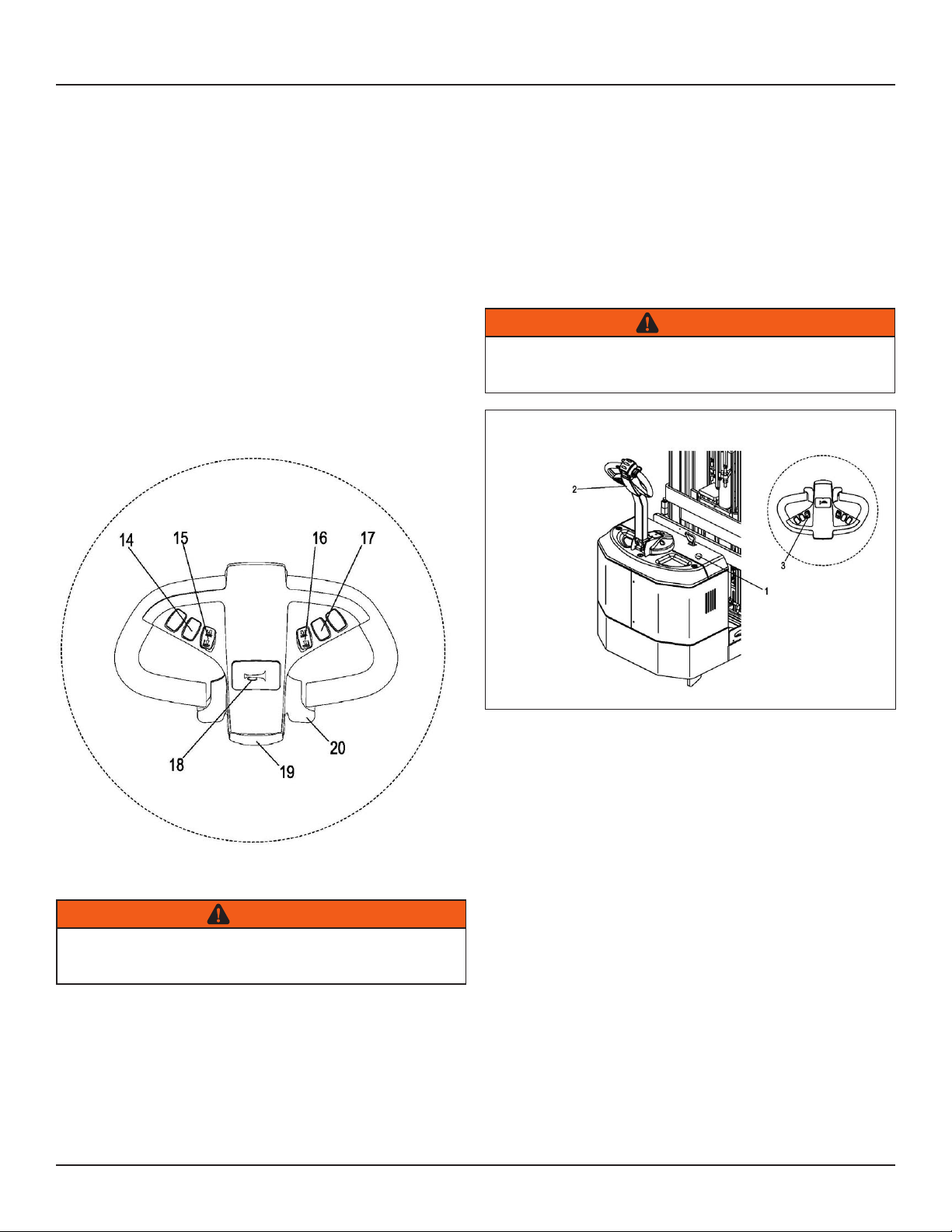
4.1 CONTROL HANDLE
ITEM COMPONENT FUNCTION
14 Control shaft with control shaft head drive wheel Tilting the mast backward or forward
15 Reach backward & forward button Rech the mast backward or forward
16 Lower & Lift switch Lowers or raises load forks
17 Sides way switch Sides way the fork
18 Warning signal button Triggers a warning signal
19 Collision safety switch Safety function which, when activated, forces the reach truck to re-
verse until the switch is restored to neutral
20 Travel switch Controls the driving speed and direction
4.1.1 KEY SWITCH
Switches control current on and off. Removing the key prevents the
Reach Truck from being switched on by unauthorised personnel.

BGNR-30 POWERED WALKIE REACH STACKER—OWNER’S MANUAL
12 ISSUE DATE: MARCH 16, 2016 REV.0 (PART # 038-969E)
4.1.2 BATTERY DISCHARGE INDICATOR
The LEDs (1) represent battery residual capacity, The LCD (2)
displays the operating hours.
Battery Discharge Indicator (1)
When the Reach Truck has been released via the key switch, the
battery charge status is displayed.
The colours of the LEDs (1) represent the following conditions:
COMPONENT LED COLOR VALUE
Standard battery
residual capacity
GREEN 70 - 100%
ORANGE 50 - 60%
FLASHING RED 0 - 20%
ITEM DESCRIPTION CQE15A UNIT
Drive Unit Battery
Operator Type Pedestrian
Q Load Capacity 3300 lb
C Load Center 23.6 in
Travel speed, laden /
unladen 3.4 / 3.7 mph
Lifting speed, laden /
unladen 28.5 / 33.4 fpm
Lowering speed, laden /
unladen 49.2 / 29.5 fpm
Reaching speed, laden /
unladen 15.7 / 15.7 fpm
ITEM DESCRIPTION CQE15A UNIT
Maximum gradeability, laden/
unladen 6 / 10 °
Service weight
(with battery) See form B lb
Loading
Unladen, Front/Rear,
fork advanced 2690/1698 lb
Unladen, Front/Rear,
fork retracted 2932/1433 lb
Laden, Front/Rear,
fork advanced 1212/6922 lb
Laden, Front/Rear,
fork retracted 2690/5247 lb
Drive motor rating S2 60 min 4.4 kW
Lift motor rating at S3 15% 5.36 kW
Battery Discharge for 70%, A flashing red show on storage battery charge warning. Battery Discharge for 80%, Two flashing reds show
on battery charge used up warning, Lifting is now inhibited. The battery must be charged.
Operating hours display(2)
Display range between 0.0 and 99,999.0 hours. Travel and lifting are logged. This is a backlit display.
Power up test
On power up the display shows:
• The operating hours
• The charge status
4.1.3 STANDARD VERSION SPECIFICATIONS
Technical specification details in accordance with JB/T3773.1-84. Technical modifications and additions reserved.
4.1.4 PERFORMANCE DATA FOR STANDARD REACH TRUCKS

BGNR-30 POWERED WALKIE REACH STACKER—OWNER’S MANUAL
13ISSUE DATE: MARCH 16, 2016 REV.0 (PART # 038-969E)
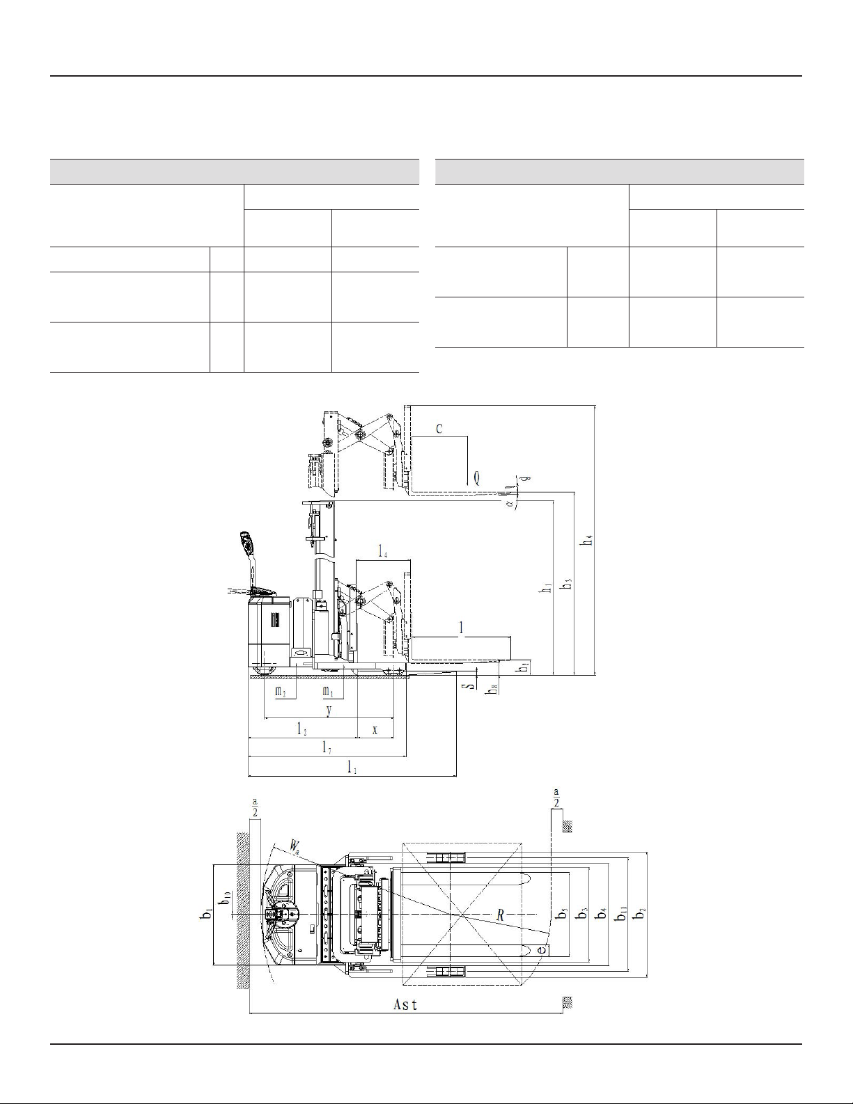
4.1.5 DIMENSIONS
ITEM DESCRIPTION CQE15A UNIT
y Wheelbase 54.9 in
h1Height, mast lowered 83 in
h2Free lift 6.3 in
h3Lift height 126 in
h4Height, mast extended 162.8 in
h7
Seat height / standing
height /
h8Height of wheel arms 5.3 in
l1Overall length 88.6 in
l2Length to face of forks 46.5 in
b1/b2Overall width 33.5/41.7 in
b3Fork frame width 31.5 in
b5
Distance between fork
arms 7.8 - 28 in
b4
Distance between wheel
arms / loading surfaces 33.8 in
a/b Tilt of mast / fork carriage
forward / backward 3/3 °
l4Reach distance 23.2 in
m1
Ground clearance, laden,
below mast 2.75 in
FORM A:
STANDARD MAST TYPES (in)
Mast
Types
Close
Mast
Height
Free
Height
Lift
Height
Extended
Mast Height
h1 h2 h3 h4
Two Stage
Mast
1940 0 2700 3660
2090 0 3000 3960
Three Stage
Mast 1960 1000 4000 4955
FORM B:
SERVICE WEIGHT (include battery) (lb)
Mast
Types Mast Height
Service Weight (lb)
CQE15A
Two Stage
Mast
102.36 4160.12
125.98 4299.01
Three Stage
Mast 157.48 4629.71
ITEM DESCRIPTION CQE15A UNIT
m2
The minimum ground
clearance of frame 3.5 in
Ast Aisle width1, 1000 x 1200
pallet crossways
See Form
Cin
Ast Aisle width1, 800 x 1200
pallet lengthways
See Form
Cin
Wa Outer turning radius 62.6 in
I7
Length across wheel
arms (exclusive fork) 67.3 in
Tyre type PU/PU
Tyre size, driving wheels Ø10.2 x 4.1 in
Tyre size, loading wheels Ø 4 x 2.8 in
Tyre size, caster wheels —
Wheels, number driving,
caster / loading (x - drive
wheels)
1x , 4
b10
Track width, front, driving
side 0 in
b11
Track width, rear, loading
side 37.8 in
1) Including safety distance a = 7.87 in.
2) Sound pressure level at the driver’s ear 74 dB(A)
BGNR-30 POWERED WALKIE REACH STACKER—OWNER’S MANUAL
14 ISSUE DATE: MARCH 16, 2016 REV.0 (PART # 038-969E)
FORM C:
LENGTH ACROSS WHEEL ARMS
Mast Types
CQE15A
Two Stage
Mast
Three Stage
Mast
Overall length (min) (lb) I188.62 89.17
Aisle width for pallets
1000 x 1200
crossways (lb)
Ast 104.06 104.45
Aisle width for pallets
800 x 1200
lengthways (lb)
Ast 105.91 106.42
FORM C:
LENGTH ACROSS WHEEL ARMS
Mast Types
CQE15A
Two Stage
Mast
Three Stage
Mast
Aisle width for pallets
1000 x 1200
lengthways (lb)
Ast 107.80 108.27
Aisle width for pallets
800 x 1200
crossways (lb)
Ast 99.06 99.33
4.1.5 DIMENSIONS CON’T.
BGNR-30 POWERED WALKIE REACH STACKER—OWNER’S MANUAL
15ISSUE DATE: MARCH 16, 2016 REV.0 (PART # 038-969E)
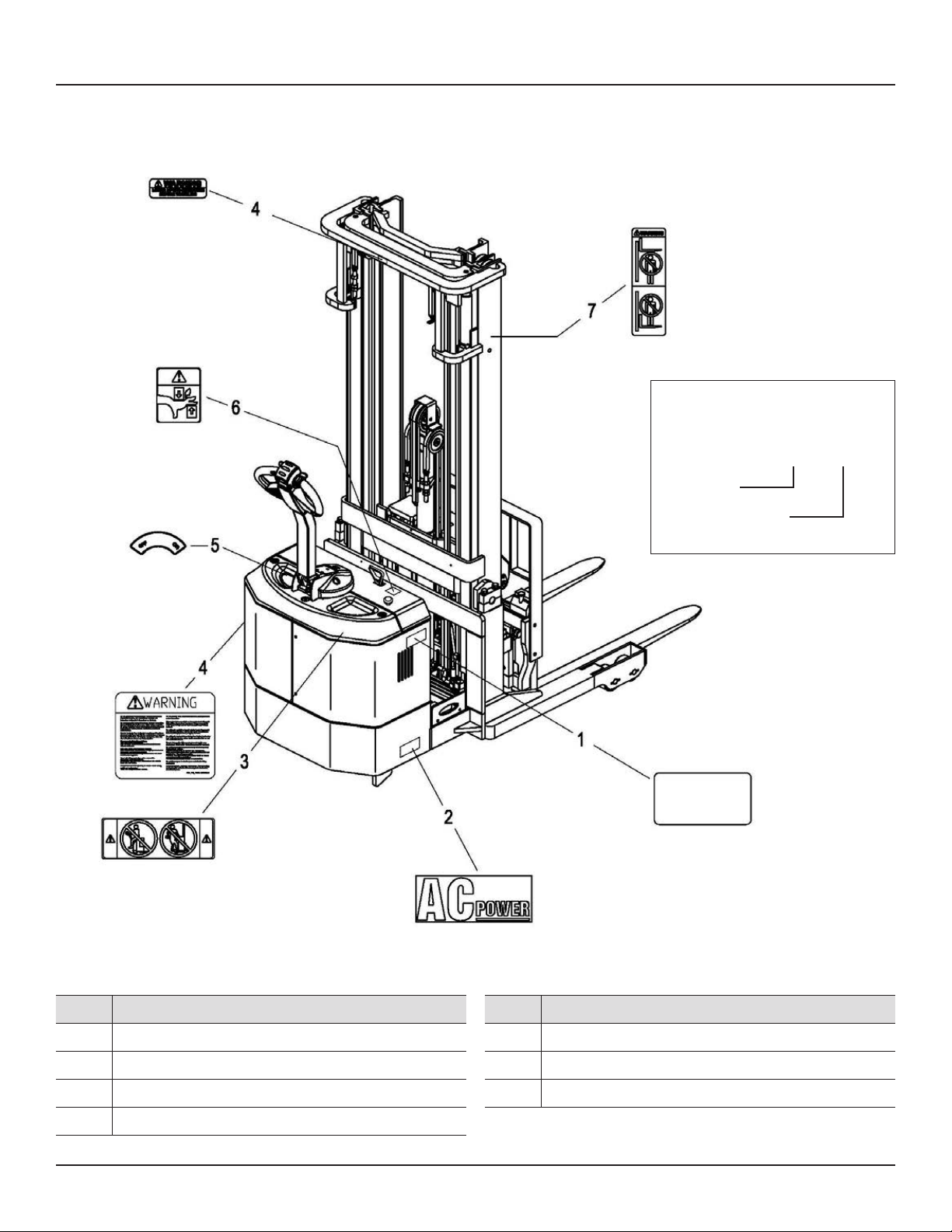
4.2 IDENTIFICATION POINTS AND SERIAL PLATES
ITEM DESCRIPTION
1 Reach Truck Serial Plate
2 AC Power Decal
3 “Never Sit” Warning Decal
4 Operator Warning Decal
ITEM DESCRIPTION
5 Key Switch Decal
6 “Never Put Your Hands in Inner and Outer” Decal
7 “Never Stand” Warning Decal
Reach Truck Serial Plate
Model Number Example:
CQE 15 A
Reach Truck
Load Capacity:
15 = 1500 kg

BGNR-30 POWERED WALKIE REACH STACKER—OWNER’S MANUAL
16 ISSUE DATE: MARCH 16, 2016 REV.0 (PART # 038-969E)
5.0 COMMISSIONING
5.1 USING THE REACH TRUCK FOR THE FIRST TIME
Only operate the Reach Truck with battery current. Preparing the
Reach Truck for operation after delivery or transport.
Procedure:
• Check the equipment is complete.
• Check the hydraulic oil level.
• Install the battery if necessary (where required), (see “7.4
Battery Removal and Installation”) do not damage battery
cable.
• Charge the battery, (see “7.3 Charging the Battery”).
When the Reach Truck is parked the surface of the tyres will flatten.
The flattening will disappear after a short period of operation.
5.2 DURING BRAKE-IN
We recommended operating the machine under light load
conditions for the first stage of operation to get the most from it.
Especially the requirements given below should be observed while
the machine is in a stage of 100 hours of operation.
• Must prevent the new battery from over discharging when early
used. Please charging when remain power less than 20%.
• Perform specified preventive maintenance services carefully
and completely.
• Avoid sudden stop, starts or turns.
• Oil changes and lubrication are recommended to do earlier
than specified.
• Limited load is 70 – 80% of the rated load.
6.0 OPERATION
6.1 SAFETY REGULATIONS FOR THE OPERATION OF
REACH TRUCKS
DRIVER AUTHORIZATION:
The Reach Truck may only be used by suitably trained personnel,
who have demonstrated to the proprietor or his representative
that they can drive and handle loads and have been authorised
to operate the Reach Truck by the proprietor or his representative.
DRIVER’S RIGHTS, OBLIGATIONS AND RESPONSIBILITIES:
The driver must be informed of his duties and responsibilities and
be instructed in the operation of the Reach Truck and shall be
familiar with the operator manual. The driver shall be afforded all
due rights . Safety shoes must be worn with pedestrian operated
Reach Trucks.
UNAUTHORISED USE OF REACH TRUCK:
The driver is responsible for the Reach Truck during the time it
is in use. He shall prevent unauthorised persons from driving or
operating the Reach Truck. It is forbidden to carry passengers or
lift personnel.
DAMAGE AND FAULTS:
The supervisor must be immediately informed of any damage or
faults to the Reach Truck. Reach Trucks not safe for operation (e.g.
wheel or brake problems) must not be used until they have been
rectified.
REPAIRS:
The driver must not carry out any repairs or alterations to the
Reach Truck without the necessary training and authorisation to
do so. The driver must never disable or adjust safety mechanisms
or switches.
HAZARDOUS AREA:
A hazardous area is defined as the area in which a person is at risk
due to Reach Truck movement, lifting operations, the load handler
(e.g. forks or attachments) or the load itself. This also includes
areas which can be reached by falling loads or lowering operating
equipment.
• Unauthorised persons must be kept away from the hazardous
area.
• Where there is anger to personnel, a warning must be sounded
with sufficient notice.
• If unauthorised personnel are still within the hazardous area
the Reach Truck shall be brought to a halt immediately.
SAFETY DEVICES AND WARNING SIGNS:
Safety devices, warning signs and warning instructions shall be
strictly observed.

BGNR-30 POWERED WALKIE REACH STACKER—OWNER’S MANUAL
17ISSUE DATE: MARCH 16, 2016 REV.0 (PART # 038-969E)
6.2 OPERATE AND RUN THE REACH TRUCK
6.2.1 PREPARING
Before the Reach Truck can be commissioned, operated or a load unit lifted, the driver must ensure that there is nobody within the
hazardous area.
Checks and operations to be performed before starting daily work
• Make sure the Emergency brake switch is depressed (6).
• Make sure the battery is connected.
• Insert the key in the key switch (14) and turn it to the right as far as it will go.
• Test the warning signal switch (13).
Visually inspect the entire Reach Truck (in particular wheels and load handler) for obvious damage.
6.2.2 TRAVEL, STEERING, BRAKING
Do not drive the Reach Truck unless the panels are closed and properly locked.
Before operating the truck, check all controls and warning devices for proper operation.
If any damage of fault is found, don’t operate truck until corrected.
WARNING

BGNR-30 POWERED WALKIE REACH STACKER—OWNER’S MANUAL
18 ISSUE DATE: MARCH 16, 2016 REV.0 (PART # 038-969E)
6.2.2 TRAVEL, STEERING, BRAKING CON’T.
1. DRIVING
DRIVING IN LOW SPEED
Push the control shaft into the slow speed range (S) and set the
driving switch to the desired driving direction (front or back).The
bigger angle it swivels, the higher the speed will get.
DRIVING IN HIGH SPEED
Push the control shaft into the quick speed range (K) and set the
driving switch to the desired driving direction (front or back). The
bigger angle it swivels,the higher speed will it get. It will get differ-
ent speed though the switch swivels the same angle in the different
range,the speed in the quick range (K) is quicker than in the slow
range(s).
2. STEERING
Apply the control handle (2) to the left or right.
3. BRAKING
The brake pattern of the Reach Truck depends largely on the
ground conditions. The driver must take this into account when
operating the Reach Truck. The driver must be looking ahead
when travelling. If there is no hazard, brake moderately to avoid
moving the load.
The Reach Truck can brake in four different ways:
• Emergency braking
• Automatic braking
• Regenerative braking
• Inversion braking
EMERGENCY BRAKING
Press Emergency brake switch(1), all electrical functions are cut
out and the Reach Truck automatically brakes.
AUTOMATIC BRAKING
When the control handle (2) is released it automatically sets itself
to the upper brake zone (B) and automatic braking ensues.
REGENERATIVE BRAKING
If the travel switch is set to “0”, the Reach Truck automatically
brakes regeneratively. When the speed below 1Km/h, the brake
then applies and motor brake stop.
INVERSION BRAKING
You can set the travel switch to the opposite direction when travel-
ling. The Reach Truck brakes regeneratively until it starts to move
in the opposite direction.
If the control handle moves slowly or not at all to the upper
brake zone, the Reach Truck must be taken out of service
until the cause of this fault is be rectified.
If the travel switch moves slowly or not at all to 0, the Reach
Truck must be taken out of service until the cause of this
fault is be rectified. Replace the control handle if necessary.
In hazardous situations set the control handle to the brake
position or set the travel switch to the opposite direction.
Before lifting a load unit the driver must make sure that it
has been correctly stowed and does not exceed the Reach
Truck’s capacity. Do not lift long loads at an angle.
Do not lift to tiptop, to avoid shorted life of oil cylinder.
WARNING
WARNING
WARNING
WARNING
WARNING
6.2.3 LIFTING, TRANSPORTING AND DEPOSITING
LOADS
Unsecured and incorrectly positioned loads can cause accidents
• Instruct other people to move out of the hazardous area of the
Reach Truck. Stop working with the Reach Truck if people do
not leave the hazardous.
• Only carry loads that have been correctly secured and posi-
tioned. Use suitable precautions to prevent parts of the load
from tipping or falling down.
• Do not transport bad handbarrow (as Reach Truck and stock).
• Never stand underneath a raised load handler.
• Do not stand on the load handler.
• Do not lift other people on the load handler.
• Insert the forks as far as possible underneath the load.
BGNR-30 POWERED WALKIE REACH STACKER—OWNER’S MANUAL
19ISSUE DATE: MARCH 16, 2016 REV.0 (PART # 038-969E)
Never tilt the mast with loads upraised 1.5m or more.
Don’t lift the load when the mast was tilted forward.
Parking the Reach Truck securely. Forbid parking on an
incline. Always fully lower the forks.
WARNING
WARNING
6.2.3 LIFTING, TRANSPORTING AND DEPOSITING
LOADS CON’T.
LIFT
Pull “Lift & Lower” switch (16) until the height you need.
LOWER
Push “Lift & Lower” switch (16) until the lowest position.
TILT FORWARD
Press “Tilting forward&backward” button (15) until the angle you
need.
TILT BACKWARD
Press “Tilting forward & backward” button (15) until the angle you
need.
6.2.4 PARKING THE REACH TRUCK SECURELY
When you leave the Reach Truck it must be securely parked even
if you only intend to leave it for a short time.
• Pull “Lower” switch (3), fully lower the load handler.
• Fully lower the forks.
• Press Emergency brake switch (1).
• Turn off the key switch and remove the key (2).

BGNR-30 POWERED WALKIE REACH STACKER—OWNER’S MANUAL
20 ISSUE DATE: MARCH 16, 2016 REV.0 (PART # 038-969E)
7.0 BATTERY MAINTENANCE & CHARGING
7.1 SAFETY REGULATIONS FOR HANDLING ACID
BATTERIES
Park the Reach Truck securely before carrying out any work on
the batteries.
MAINTENANCE PERSONNEL:
Batteries may only be charged, serviced or replaced by trained
personnel. The present operator manual and the manufacturer’s
instructions concerning batteries and charging stations must be
observed when carrying out the work.
FIRE PROTECTION :
• Smoking and naked flames must be avoided when working
with batteries.
• Wherever a Reach Truck is parked for charging there shall be
no inflammable material or operating fluids capable of creating
sparks within 2 meters around the Reach Truck.
• The area must be well ventilated.
• Fire protection equipment must be provided.
PROTECTION AGAINST ELECTRIC SHOCK:
• Battery has high voltage and energy.
• Do not bring short circuit.
• Do not approach tools to the two poles of the battery, which
can cause the sparkle.
7.2 BATTERY TYPE AND DIMENSION
Battery type and dimension are acquired at fact.
When replacing or installing batteries, ensure that the battery is
correctly secured in the battery compartment of the Reach Truck.
7.3 CHARGING THE BATTERY
SAFETY REGULATIONS FOR CHARGING THE BATTERY:
• To charge the battery, the Reach Truck must be parked in a
closed and properly ventilated room.
• Do not place any metal objects on the battery.
• Before charging, check all cables and plug connections for
visible signs of damage.
• Before start and finish charging to make sure power is turned
OFF.
• It is essential to follow the safety regulations of the battery and
charging station manufacturers.
CHARGING STEP
• Check whether the condition is according with “Safety
Regulations for Charging the Battery”
• Park the Reach Truck securely (See 6.2.4 Parking the Reach
Truck Securely)
• Remove the battery plug (1)
• Connect the battery plug (1) with the charging lead of the
stationary charger (2) and turn on the charger
NOTE: This picture is just a sample.
Table of contents
Other Blue Giant Forklift manuals


