Blue Giant BGL-33 User manual

OPERATOR’S MANUAL
BGL-33 WALKIE COUNTERBALANCED STACKER
WARNING
Do not operate or service this product unless you have read and fully
understand the entire contents of this manual. Failure to do so may result in
property damage, bodily injury or death.
ISSUE DATE: MAY 5, 2020 REV.0 (PART # 038-942E)


1
FOREWORD
As a lift truck operator, you are
responsible for a machine that is use-
ful, powerful, and can be hazardous if
not operated as described. Your
Blue Giant truck may weigh more than
some cars, depending on the
model. Observing and practicing
the safety warnings in this manual
cannot be overemphasized. Just
knowing the warnings, however, is
no substitute for common sense.
Using your com-mon sense will, in
almost all cases, prevent accidents.
Think of the truck as your own. In
this way you will learn its capabilities
and limitations.
This manual is intended to remain
with the truck at all times as a handy
reference guide to operation. Detailed
maintenance procedures are found in
the parts and service manual for the
specific truck model, and are to be
performed only by a qualified techni-
cian. For further information on
obtaining a complete parts and ser-
vice manual, see page 15 of this man-
ual.
The operator who knows his truck will
learn to spot problems as they
develop. This is accomplished by per-
forming the Daily Checks and report-
ing any problems to the designated
authority.
TABLE OF CONTENTS
SAFETY SYMBOLS ..............................................................................................2
GENERAL DESCRIPTION ....................................................................................2
NAME PLATE AND WARNING DECAL ...............................................................2
LOAD CAPACITY..................................................................................................4
BEFORE OPERATION..........................................................................................5
Optional Features....................................................................................8
INSTRUMENTS AND CONTROLS .......................................................................7
Optional Features....................................................................................8
OPERATION..........................................................................................................8
Forward and Reverse Travel and Speed Control .................................8
Steering ....................................................................................................9
Stopping...................................................................................................9
Parking ...................................................................................................10
Battery Charging ...................................................................................10
Load Handling .......................................................................................10
Moving a Disabled Truck......................................................................11
NOTICE - OBTAINING A PARTS AND SERVICE MANUAL .............................15

2
SAFETY SYMBOLS
WARNING and CAUTIONS are both signal words intended to alert the viewer to
the existence and relative degree of a hazard. They are both preceded by a safety
alert symbol consisting of an exclamation mark enclosed by a triangle.
A Warning indicates a hazard which could result in injury or death if proper pre-
cautions are not taken.
A Caution indicates a reminder of routine safety practices.
A prohibition slash (circle with diagonal slash through it) indicates a procedure or
action that should not be performed under any circumstances, as both personal
injury and/or damage to equipment will result.
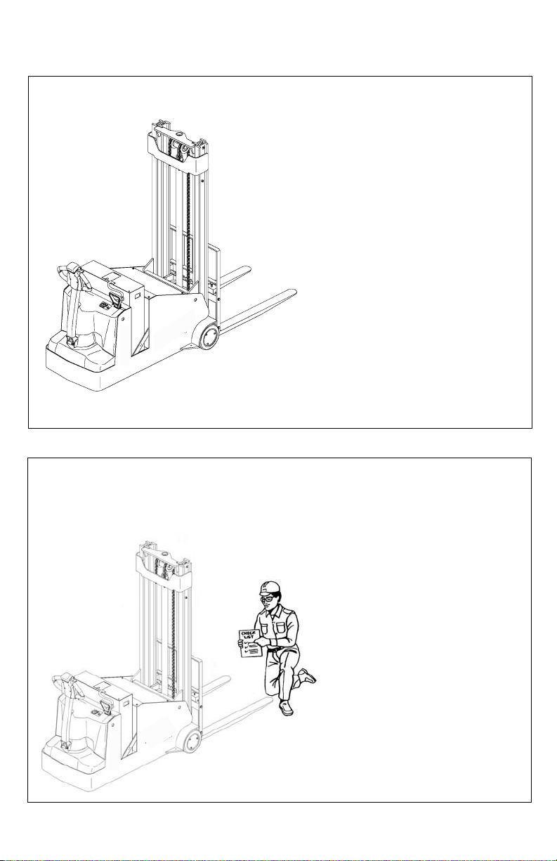
GENERAL DESCRIPTION
Trucks in the Blue Giant
Counterbalance series utilize a
weighted frame to counterbalance
the load. Some mod-els are
equipped with tilt cylinders used to
tilt the mast back during trans-port.
Control for steering, braking, forward
and reverse travel, horn and speed
control are all located on the control
handle.
All trucks feature an automatic high
speed cut-off circuit which locks out
high speed when the forks are ele-
vated.
Trucks in this series may vary in load
capacity, battery arrangement, instru-
mentation and lift/lower controls,
depending on model and options.
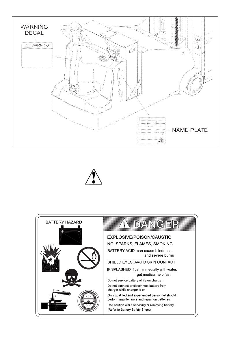
NAME PLATE AND WARNING DECAL
Name plate and warning decal loca-
tions may vary between models, but
they are always near the steering arm
within sight of the operator.
If the name plate or warning deal are
lost or damaged they should be
replaced immediately. Have your
supervisor or the designated author-
ity contact Blue Giant Authorized
Dealer for replacement.
The name plate shows the model
number; serial number; truck type;
battery type, voltage and minimum
weight; and, maximum lift height. It
also contains information on the load
capacity and load center. The warning
decal contains warnings which also
appear, with illustrations, in the Oper-
ating Precautions section of this man-
ual.
3
Name Plate and Warning Decal Locations - Typical
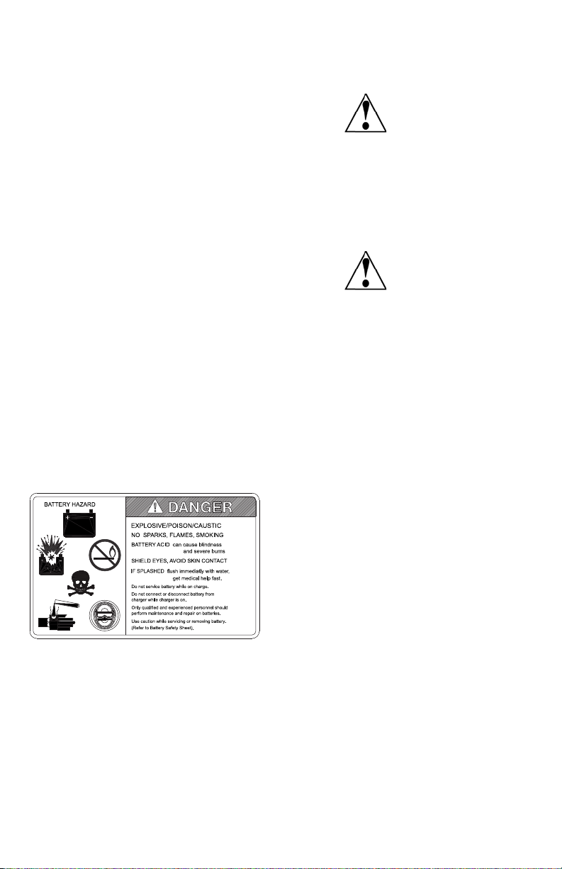
This truck is equipped with a battery. Read and heed the warning decal located
near the battery. An example is shown here:
WARNING:

4
LOAD CAPACITY
The further the load center is from the
backrest, the lower the load capacity.
The load center must also be no
higher than that specified above the
lifting surface (Top side of forks). For
example, a load capacity of 3,000
pounds with a load center of 24
inches means that the can be used to
lift 3,000 pounds only when the load’s
center of gravity is no more than 24
inches from the face of the forks or 24
inches above the top side of the forks.
Note that a truck undergoing speed
changes is less stable than a standing
truck. If you are not sure that the truck
can lift a certain load, consult your
supervisor or the designated author-
ity.
Load Center
R3814
5
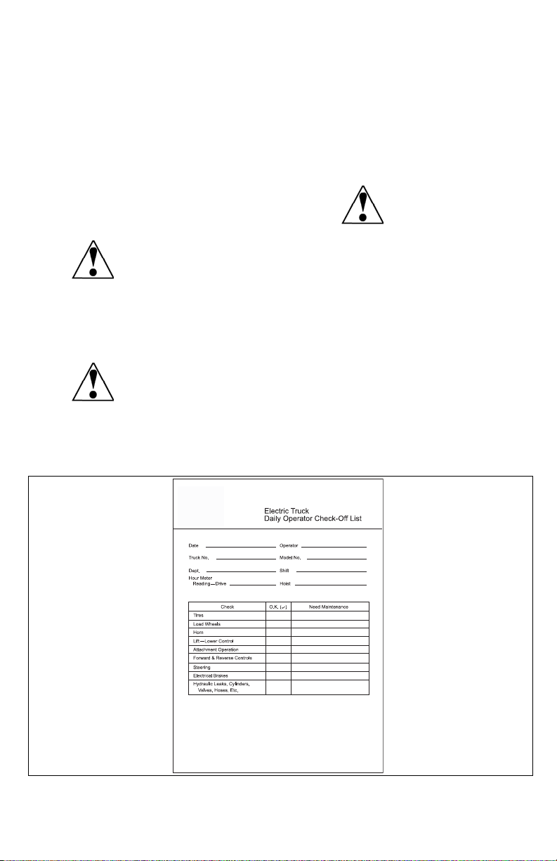
BEFORE OPERATION
The table on page 6 covers important
inspection points on trucks which
should be checked prior to operation.
Depending on use, some trucks may
require additional checks.
The illustration below shows a sample
format for a Operator Checklist, which
can be modified as necessary to fit
your operation.
Periodic maintenance of this
truck by a QUALIFIED TECH-
NICIAN is required.
A QUALIFIED SERVICE
TECHNICIAN should check the
truck monthly for proper lubri-
cation, proper fluid levels,
brake maintenance, motor
maintenance and other areas
specified in the parts and ser-
vice manual maintenance sec-
tion.
If the truck is found to be
unsafe and in need of repair, or
contributes to an unsafe condi-
tion, report it immediately to the
designated authority. Do not
operate it until it has been
restored to a safe operating
condition. Do not make any
unauthorized repairs or adjust-
ments. All service must be per-
formed by a qualified
maintenance technician.
Sample of Operator Check List
WARNING:
WARNING:
WARNING:
R6235

6
Operator Checks
ITEM PROCEDURE
Transmission and hydraulic
systems
Check for signs of fluid leakage.
Forks Check for cracks and damage and that they
are properly secured.
Chains, cables and hoses Check that they are in place, properly secured
and not damaged.
Guards and load backrest Check that safety guards are in place, prop-
erly secured and not damaged.
Safety signs Check that warning labels, nameplate, etc.,
are in good condition and legible.
Horn Check that horn sounds when operated.
Steering Check for binding or looseness in steering
arm when steering.
Travel controls Check that speed controls on control handle
operate in all speed ranges in forward and
reverse and that belly button switch functions.
Wheels Check drive wheel for cracks or damage.
Move truck to check load wheels for freedom
of rotation.
Hydraulic controls Check operation of lift and lower, and tilt to
their maximum positions.
Brakes Check that brakes actuate when steering arm
is raised to upright position, and when lowered
to horizontal position. Check that dynamic
brake (if so equipped) actuates when dynamic
brake pushbutton on control handle is
pressed.
Deadman/Parking brake Check that steering arm raises to upright posi-
tion when released and brake applies.
Battery disconnect Check that battery can be disconnected and
reconnected. Check for connector damage.
High speed limit switch Allow for enough space to operate truck in
high speed. Elevate forks approximately two
feet, then test drive truck to check if high
speed is cut out.
7
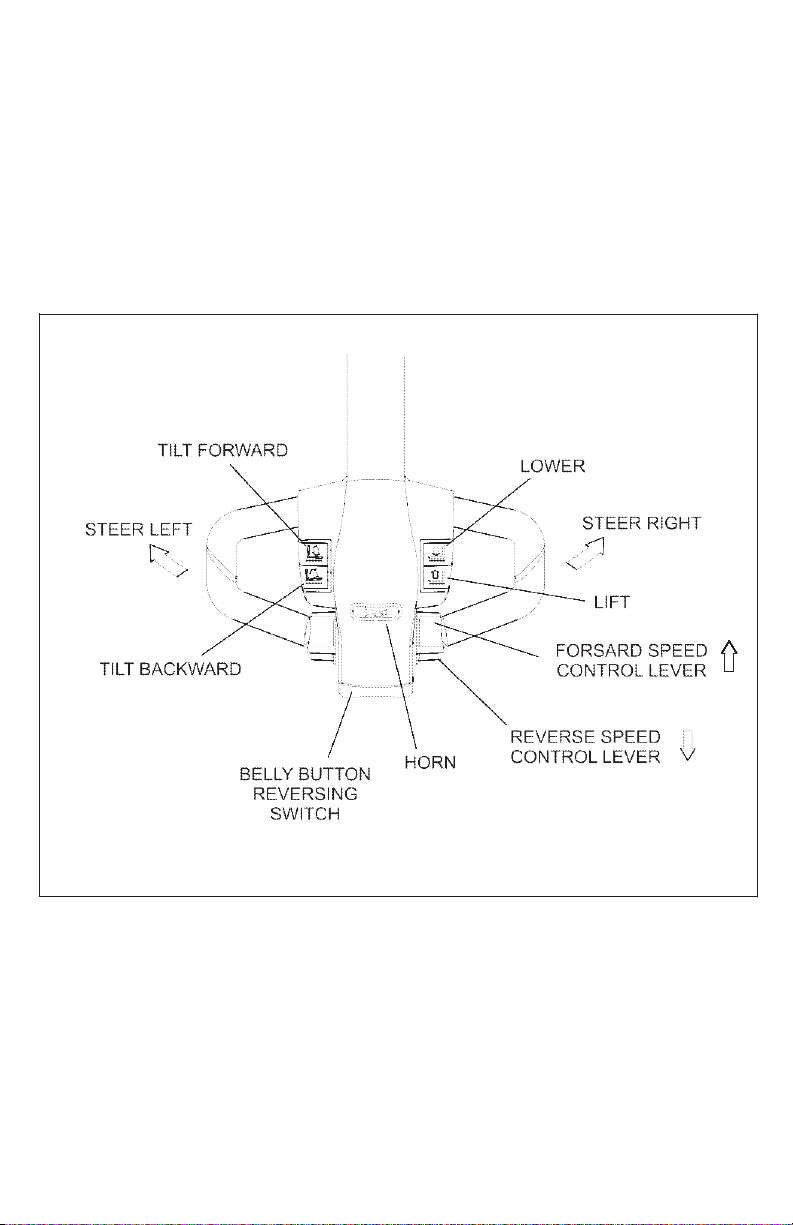
INSTRUMENTS AND CONTROLS
The steering arm and control handle
provide controls for steering, forward
and reverse speed control, braking,
horn, and raising and lowering the
forks. Control handles on all models
have a “belly-button” reversing switch
which reverses the direction of the
truck upon contact with the operator.
Detailed operating instructions are in
the Operation section of this manual.
A battery disconnect is mounted near
the steering arm. Pulling the discon-
nect removes all power from truck cir-
cuits in the event of an emergency.
Control Handle
8
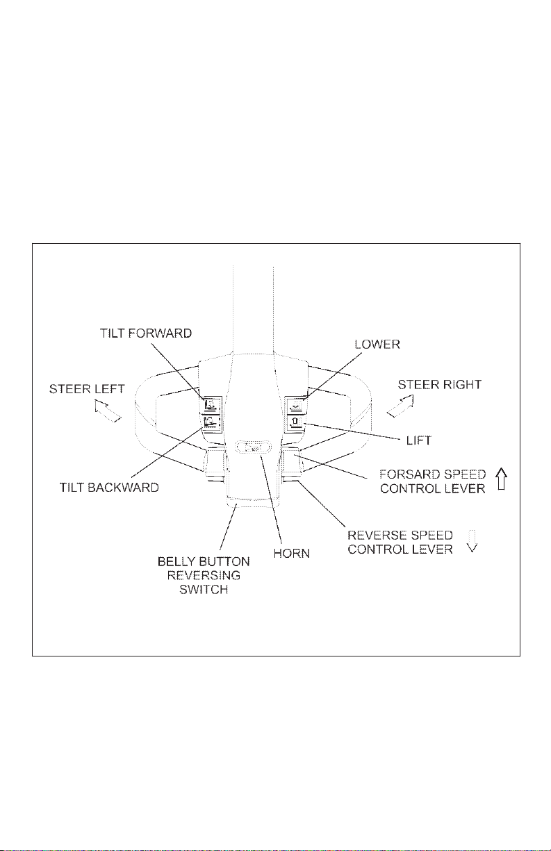
OPERATION
Forward and Reverse Travel and
Speed Control
All directional and speed controls are
located on the control handle.
Forward and reverse are controlled by
rotating the speed control lever as
shown. The lever is spring loaded to
return to neutral when released. Fur-
ther rotation in either direction will
progress the truck from slow to maxi-
mum travel speed.
To change directions or to stop the
truck, rotate the speed control lever in
the opposite direction. The truck will
come to a stop and then, unless the
controls are returned to the center
neutral position, accelerate in the
opposite direction.
Control Handle
9
Steering
Moving the control handle (which con-
nects to the steering arm) right or left
will turn the truck right or left. When
maneuvering around corners, make
square turns and be sure there is
adequate clearance.
Stopping
Stop the truck as gradually as possi-
ble. Unnecessary rapid stopping could
be hazardous. Load could become
unstable.
There are four possible ways to stop
the truck:
1. Plugging: This electrical braking
function consists of rotating the
speed control lever in the oppo-
site direction of travel and then
releasing it when the truck stops.
Plugging is a convenient way to
stop the truck during normal
operation. If the control is not
released, the truck will accelerate
in the opposite direction.
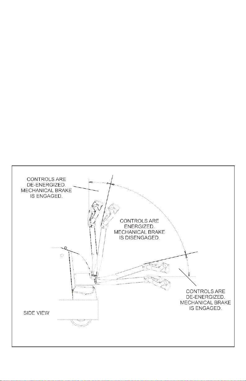
2. Steering arm: The brake is fully
applied by lowering or raising the
steering arm. All traction control
power is shut off when the bake
is engaged. When the steering
arm is in te upright position, the
brake acts as a parking brake.
Deadman braking occurs when
the handle is released and spring
action raises steering arm to the
upring position.
10
Steering Arm Braking Positions
3. Regenerative Braking: If the
speed contrrol lever is released,
the truck automatically brakes
regeneratively. When the speed
is below 0.5 MPH, the brake
applies.
Parking
When parking the truck, do not
obstruct traffic lanes or aisles.
1. Park the truck in its designated
parking area.
2. Raise the steering arm until verti-
cal to apply the parking brake.
3. Fully lower forks.
4. Turn keyswitch (if so equipped) to
off position. Remove key for
added security.
5. Pull out battery disconnect.
Battery Charging
Refer to DOC 245 for battery safety
and maintenance.
NOTE: Battery charging instructions
are contained in the service
manual.
Load Handling
Handle only loads arranged for
stability and always use cau-
tion. Raise and lower the load
smoothly to prevent the load
from falling.
Always be sure the load and
load center are within the
capacity of the truck. If in doubt
check the nameplate.
1. Approach the load slowly.
2. Stop the truck when the forks are
just in front of the load.
3. Adjust the forks to the maximum
practical width to support the load
to be lifted.
4. Raise or lower the forks until they
are properly aligned with the pal-
let openings.
5. Move the truck slowly into posi-
tion so that the forks are centered
about the load.
6. Make sure the load is against the
backrest and then raise the forks
until the pallet clears the rack. Tilt
(if so equipped) the forks slightly
backward.
WARNING:
WARNING:

11
7. Move the truck away from the
rack until the load clears the rack
and then lower the forks.
8. Lead the truck by the control han-
dle with the load trailing except
when in confined areas. Ramps
should be traveled with operator
uphill of truck when empty, or
operator downhill of truck with
load on forks.
9. Always look in the direction of
travel. Move slowly and check
clearances when approaching
obstructions.
10. Do not make sudden starts and
stops. Operate truck smoothly
and gradually.
11. Travel slowly and squarely
around corners. Remember that
the trailing load wheels do not fol-
low the turn path of the drive
wheel; instead, they tend to cut
the corner.
12. Line up the truck with the unload-
ing area.
13. Stop the truck and raise or lower
the forks until the pallet is in posi-
tion with the unloading area.
14. Check the load alignment with
surrounding objects.
15. Be careful not to damage or
move adjacent loads and objects.
16. Slowly move into position.
17. Lower the forks and tilt forward
until the load is resting on its own.
Be sure there is no downward
force on the forks on the rack or
floor.
18. Move the truck back until the
forks are clear of the pallet.
19. If forks are elevated, lower to
travel position.
Moving a Disabled Truck
Do not attempt to move a disabled
truck; notify your supervisor or proper
authority.
12
The following operating instructions appear on the truck warning decal, which is
located near the steering arm.
R7059
Do not operate this truck unless you
have been trained and authorized to do
so, and have read and understand all
warnings and instructions contained in
this operator’s manual and on this truck.
Do not operate this truck until you have
checked its condition. Give special atten-
tion to tires, horn, lights, battery, control-
ler, lift systems (including forks or
attachments, chains, cables and limit
switches), brakes, steering mechanism,
guards and safety devices. If you
have any questions, notify your
supervisor or proper authority.
R7060
13
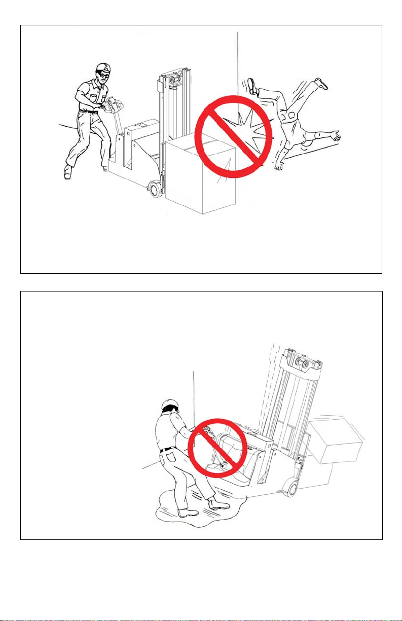
Observe applicable traffic regulations. Yield right-of-way to pedestrians.
Slow down and sound horn at cross aisles and wherever vision is
obstructed.
R7056
R7066
Start, stop, travel, steer and brake
smoothly. Slow down for turns and on
uneven or slippery surfaces that could
cause truck to slide or overturn. Use
special care when traveling without
load as the risk of overturn may be
greater.
14
R7071
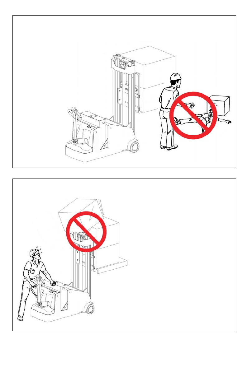
Do not handle unstable or loosely
stacked loads. Use special care when
handling long, high or wide loads to
avoid losing the load, striking
bystanders or
tipping the truck.
R7072
Do not handle loads which are higher
than the load backrest or load backrest
extension unless load is secured so that
no part of it could fall backward.

15
NOTICE - OBTAINING A PARTS AND SERVICE MANUAL
A complete parts and service manual covering this truck is available from Blue
Giant Manufacturing Company. To order, obtain the serial number of your
truck and contact your Blue Giant Authorized Dealer.

Corporate 410 Admiral Blvd
Mississauga, ON, Canada L5T 2N6
t905.457.3900 f905.457.2313
USA 6350 Burnt Poplar Road
Greensboro, NC 27409
www.bluegiant.com
If calling within North America: t1.800.668.7078 f1.888.378.5781 ©Copyright Blue Giant Equipment Corporation 2020
Other manuals for BGL-33
1
Table of contents
Other Blue Giant Forklift manuals


