Blue Giant BG ZERO User manual

OWNER’S MANUAL
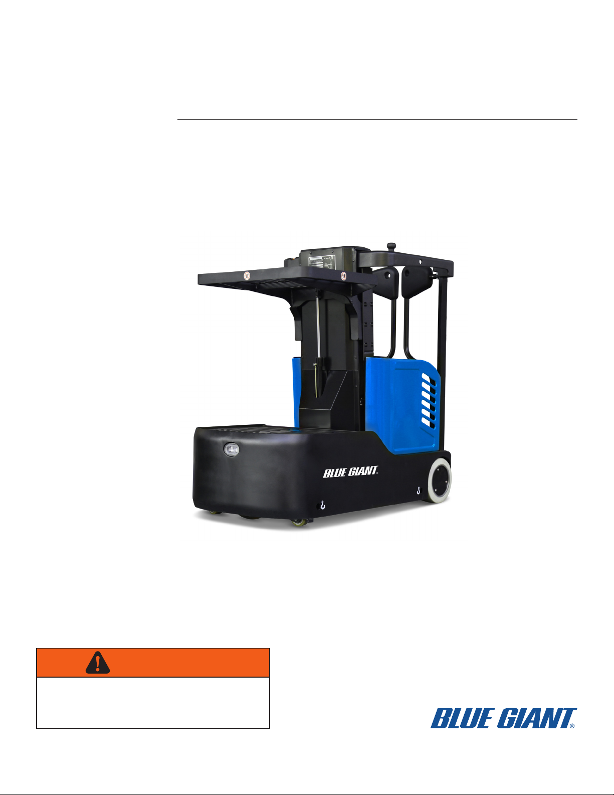
BG ZERO TASK SUPPORT VEHICLE
WARNING
Do not operate or service this product unless you have
read and fully understand the entire contents of this
manual. Failure to do so may result in property damage,
bodily injury or death.
ISSUE DATE: DECEMBER 7, 2020 REV. 1.0 (PART # 038-XXXXE)
ACTUAL PRODUCT MAY NOT APPEAR EXACTLY AS SHOWN

WARNING
Do not operate this vehicle unless you have been
authorized and trained to do so, and have read all
warnings and instructions in Operator’s Manual and on
this vehicle. Read, understand and comply with the
information on the vehicle’s nameplate at all times.
Do not operate this vehicle until you have performed
the daily operation’s check list. Verify and inspect tires,
horn, battery, controller, lift and hydraulic systems,
brakes, steering mechanism and guards. Verify that all
emergency controls, personal protection and safety
devices are in place and functioning correctly and
ensure the vehicle is free of fluid leaks and has no
loose or missing parts. Report any problems to the
designated authority and do not use the vehicle until
they are corrected by a qualified mechanic.
This vehicle must not be modified without the
manufacturer’s consent. Components critical to the
vehicles stability such as batteries shall not be
replaced with lighter weight components.
Operate vehicle only from designated platform operat-
ing position. Use this vehicle indoors on level surfaces
only. Never operate on ramps and slopes or uneven
floors. This vehicle is not for use on mezzanines or
balcony areas. Before operating, inspect the floor area
it will be used on and be certain it will support the
vehicle at full capacity and lift height. Identify and
avoid holes, drop-offs, bumps and obstructions.
Before and during all vehicle operations ensure that
adequate clearance is maintained from overhead
obstructions and energized electrical conductors and
parts.
Before elevating platform be sure access gates are in
position. Keep feet on platform floor at all times while
using vehicle, never climb onto access gates or
platform shelf. Do not use ladders, planks or other
devices to achieve additional height on platform.
When transferring loads to platform or platform shelf,
do not exceed capacity ratings on vehicle nameplate.
Ensure loads are centered and do not contact any
obstructions in the vehicle’s vicinity. Do not stabilize
the platform by contact with adjacent objects such as
racks or shelving. Do not use the platform as a crane.
Take care to prevent electrical cords, hoses or other
equipment from entangling in platform. Ensure area
surrounding the vehicle is free of personnel and
equipment before lowering platform.
Maintain a clear view of the ground while travelling and
a safe distance from obstacles in the vehicle or
platform’s path. Ensure personnel in the vicinity are
aware of the vehicle’s movement. Travel at a safe
speed for the conditions the vehicle is operating in.
Observe applicable traffic regulations. Yield right of
way to pedestrians. Slow down and sound horn at
cross aisles and wherever vision is obstructed. Avoid
hazardous locations.
Enter and exit platform only through open access
gates and with the platform fully lowered and vehicle
stopped. When leaving vehicle unattended, remove
key to prevent unauthorized use.
2

TABLE OF CONTENTS
Section Page Section Page
1 DESCRIPTION ............................................................1-1
1-1 INTRODUCTION ..........................................1-1
1-2 GENERAL DESCRIPTION ...........................1-1
1-3 DATA PLATE AND WARNING DECAL ........1-3
1-4 INSTALLATION / WARRANTY
CHECK LIST.................................................1-3
2 PLANNED MAINTENANCE ........................................2-1
2-1 GENERAL.....................................................2-1
2-2 MONTHLY AND QUARTERLY CHECKS.....2-1
2-3 FREQUENT INSPECTIONS.........................2-1
2-4 ANNUAL INSPECTIONS..............................2-1
2-5 BATTERY CARE ..........................................2-1
2-5.1 General.....................................................2-1
2-5.2 Safety Rules .............................................2-2
2-5.3 Maintenance Personnel............................2-2
2-5.4 Battery Care and Charging.......................2-2
2-5.5 Battery Cleaning .......................................2-2
2-5.6 Maintenance Free Batteries .....................2-2
2-6 CHARGING BATTERIES..............................2-3
2-7 REPLACING BATTERIES ............................2-3
2-7.1 Battery disposal ........................................2-3
2-8 LUBRICATION..............................................2-4
2-9 LIFT CHAIN MAINTENANCE .......................2-4
3 TROUBLESHOOTING ................................................3-1
3-1 GENERAL.....................................................3-1
3-2 CONTROLLER TROUBLESHOOTING ........3-4
3-2.1 Zapi Handset ............................................3-4
3-2.2 Fault Detection .........................................3-4
3-2.2.1 General.................................................3-4
3-2.2.2 Logbook Access...................................3-4
3-2.3 Testing Vehicle Operation ........................3-4
3-2.4 Factory Settings........................................3-5
4 STEERING SYSTEM ..................................................4-1
4-1 CONTROL ARM ...........................................4-1
4-1.1 Steering Control Removal ........................4-1
4-1.2 Steering Control Installation .....................4-2
4-2 FRONT COMPARTMENT COVER...............4-2
4-2.1 Cover Removal.........................................4-2
4-2.2 Cover Installation......................................4-2
4-3 REAR COMPARTMENT COVER.................4-2
4-3.1 Cover Removal.........................................4-2
4-3.2 Cover Installation......................................4-2
4-4 STEERING MOTOR .....................................4-3
4-4.1 Motor Removal .........................................4-3
4-4.2 Motor Installation ......................................4-3
5 BRAKE SERVICING....................................................5-1
5-1 BRAKES .......................................................5-1
5-1.1 Brake Assembly Replacement .................5-1
6 TRANSMISSION, DRIVE WHEEL,
LOAD WHEEL AND CASTERS.................................. 6-1
6-1 TRANSMISSION AND DRIVE MOTOR....... 6-1
6-2 LOAD WHEEL.............................................. 6-2
6-2.1 Removal................................................... 6-2
6-2.2 Installation................................................ 6-2
6-3 DRIVE WHEEL ............................................ 6-2
6-4 CASTER....................................................... 6-2
7 ELEVATION SYSTEM SERVICING............................ 7-1
7-1 GENERAL .................................................... 7-1
7-2 LIFT CHAIN LENGTH ADJUSTMENT......... 7-1
7-3 LIFT CHAIN WEAR INSPECTION............... 7-2
7-4 LIFT CHAIN REPLACEMENT...................... 7-2
7-4.1 Three Stage Mast .................................... 7-2
7-4.1.1 Mast Lifting Chain................................ 7-2
7-5 LIFT CYLINDERS ........................................ 7-2
8 HYDRAULIC SYSTEM SERVICING........................... 8-1
8-1 LINES AND FITTINGS................................. 8-1
8-2 HYDRAULIC PUMP, MOTOR,
AND RESERVOIR ASSEMBLY ................... 8-1
8-2.1 Removal................................................... 8-1
8-2.2 Installation................................................ 8-3
8-2.3 Disassembly and Reassembly................. 8-3
8-3 LIFT CYLINDER - MAIN .............................. 8-3
8-3.1 Removal................................................... 8-3
8-3.2 Repair ...................................................... 8-4
8-3.3 Installation................................................ 8-4
8-4 LIFT CYLINDER - TRAY.............................. 8-4
8-4.1 Removal................................................... 8-4
8-4.2 Repair ...................................................... 8-4
8-4.3 Installation................................................ 8-4
9 ELECTRICAL COMPONENTS................................... 9-1
9-1 ELECTRICAL CONTROL PANEL................ 9-1
9-1.1 Maintenance ............................................ 9-1
9-1.2 Cleaning................................................... 9-1
9-1.3 Panel Removal......................................... 9-1
9-1.4 Panel disassembly ................................... 9-1
9-1.5 Panel Installation...................................... 9-1
9-2 HORN REPLACEMENT............................... 9-1
9-3 LOWERING BUZZER REPLACEMENT ...... 9-3
9-4 LEVEL SENSOR BUZZER
REPLACEMENT .......................................... 9-3
9-5 LEVEL SENSOR REPLACEMENT.............. 9-3
9-6 WARNING LIGHT REPLACEMENT ............ 9-3
9-7 BLUE LIGHT REPLACEMENT .................... 9-3
9-8 BATTERY REPLACEMENT......................... 9-4
9-9 BATTERY CHARGER.................................. 9-4
9-9.1 Removal................................................... 9-4
9-9.2 Installation................................................ 9-4
9-10 PLATFORM CABLE REPLACEMENT......... 9-5
9-10.1 Three Stage Mast .................................... 9-5
10 OPTIONAL EQUIPMENT ......................................... 10-1
10-1 INDUSTRIAL BATTERY ........................... 10-1
11 ILLUSTRATED PARTS BREAKDOWN......................11-1
3

4

SECTION 1
DESCRIPTION
1-1. INTRODUCTION.
This publication describes the 24 volt BG Zero
Electric Access Vehicle by Blue Giant. Included are
planned maintenance instructions, lubrication
procedures, corrective maintenance procedures and
a complete parts list with part location illustrations.
Users shall comply with all requirements indicated in
applicable OSHA standards and the current edition of
A.N.S.I. A92.6. By following these requirements and
the recommendations contained in this manual, you
will receive many years of dependable service from
your BG Zero Electric Access Vehicle.
1-2. GENERAL DESCRIPTION.
The self-propelled BG Zero Electric Access Vehicle
Electric Access Vehicle lifts and transports up to 750
pounds capacity including load and operator. The
vehicle enables general maintenance work and
efficient selection and moving of materials in any area
or at any level of the warehouse or storeroom. This
vehicle is not for use on mezzanines or balcony
areas. The design per-mits one man to perform all
operations of selecting stock, driving vehicle, and
replacing the stock at the designated place. The
battery-powered vehicle is quiet and allows operation
in closed areas without special provisions for
ventilation.
Figure 1-1 BG Zero Elevating Work Platform
R8521
ITEM COMPONENT
1 Control panels
2 Storage tray
3Lift mast
4 Lower storage tray
5 Drive wheel
6 Controller
7Caster
8 Emergency stop switch
9 Charger socket
10 Battery
11 Frame
12 Load wheels
13 Operator platform
14 Hydraulic pump assembly
15 Warning light
16 Access gates
17 Emergency operation area
18 Blue Lamp
19 “Deadman” foot switch
ITEM COMPONENT
5

Figure 1-2
ITEM CONTROL / DISPLAY FUNCTION
1 Display unit Operating information and alarm fault on display.
2 Lift button (tray) Lift the storage table.
3 Lowering button (tray) Lower the storage table.
4 Horn button Activates the horn.
5 Lift button (platform) Lift the lift platform.
6 Lowering button (platform) Lower the lift platform.
7 Key switch
Switches control current on and off. Removing the key
prevents the order picker from being switched on by
unauthorized personnel.
8Emerg. power disconnect switch
Disconnects the supply current, deactivates all
electrical functions, causing the order picker to brake
automatically.
9Travel switch Select the required driving direction.
10 Right “Deadman switch Apply the right drive pedal to start up the order
picker.
11 Steering wheel Steers the order picker in the required direction.
12 Sensor switch for accelerator The right hand must be placed in the position of the
sensor switch to drive the order picker to move.
13 Emerg. power disconnect switch
Disconnects the supply current, deactivates all
electrical functions, causing the order picker to brake
automatically.
14 Emergency lowering valve Used to manually lowering the platform.
6

The motor propels the vehicle in forward or reverse
direction. The vehicle can be driven with the platform
raised or lowered; however the speed is restricted
above 20”.
On demand power steering makes the vehicle highly
maneuverable.
The control arms are used to operate the work vehicle
and provide operator safety.
The pick tray is used to place and transport merchan-
dise, equipment and tools.
The operator platform contains the “Deadman”
footswitch which must be depressed for the vehicle to
operate.
1-3. DATA PLATE AND WARNING DECAL.
Warning decals are located on the mast cover. The
name plate is mounted on the center of the mast
cover.
If the data plate or warning decals are lost or damaged
they MUST be replaced immediately. Have your
supervisor or the designated authority contact Blue
Giant Authorized Dealer for replacement.
The data plate shows the model, serial number,
capacity, lift height, vehicle weight and minimum
battery weight. See Figure 1-3.
1-4. INSTALLATION / WARRANTY CHECK LIST.
The Blue Giant Installation and Warranty Registra-
tion Reports are used to initiate the start of the war-
ranty period to the original end user.
This report also serves as documentation that all items
on the Installation and Warranty Registration Report
were reviewed and discussed with the end user prior
to taking receipt of the equipment.
This report must be completed and returned to Blue
Giant within fifteen (15) days of receipt of
equipment.
Figure 1-3 BG ZeroData Plate
R8522
7

Warranty Claim Form
ATTN: WARRANTY MANAGER Email: customersupport@bluegiant.com
Dealer ID # Dealer Name Claim Form Date (MM/DD/YYYY)
Has Unit Been Maintained / Lubricated as Specified in Accordance with Owner’s Manual?
Yes No
Equipment Model # Serial # Customer
Date of Equipment Sale (MM/DD/YY) Hour Meter Reading Customer Address
Equipment Purchase Invoice # Dealer Repair Order # City / State / Province
Submitted By (Print Full Name) Title Zip / Postal Code
Phone: Fax: Email:
Labor Total Hours: Rate: Labor Total: $ Start Date
(MM/DD/YY)
Travel Total Hours: Rate: Labor Total: $ Start Date
(MM/DD/YY)
Description of Fault:
Nature of Fault:
Corrective Procedure (Full Details Required, Incomplete Information will Delay Process)
Blue Giant Part # Part Description QTY. Blue Giant Replacement
Part(s) Invoice Number(s) Price Total
$$
$$
$$
$$
$$
Freight P E The totals calculated on this form are estimates only. Warranty guidelines may apply. Final totals will appear on your
warranty invoice. Please go to www.BlueGiant.com for Warranty Coverage and Warranty Guidelines for your product. $$
GL # WC # RGA#
A confirmation receipt will be faxed back with a warranty claim number attached. If Blue Giant deems that part(s) need to be returned, an RGA numbered form
will be faxed as well. Please include a copy of the RGA form with returning part(s) to Blue Giant Brampton location only.
0.00
0.00
0.00
0.00
0.00
0.00
0
0

SECTION 2
PLANNED MAINTENANCE
2-1. GENERAL.
Planned maintenance consists of periodic visual and
operational checks, inspection, lubrication, and sched-
uled maintenance designed to catch an issue in the
early hours or discover malfunctions and defective
parts. The operator performs the checks in the
Operator’s Manual, and refers any required
servicing to a qualified maintenance technician who
performs the planned maintenance and any required
servicing.
2-2. MONTHLY AND QUARTERLY CHECKS.
Table 2-1 is a monthly and quarterly inspection and
service chart based on normal usage of equipment
eight hours per day, five days per week. If the vehicle
is used in excess of forty hours per week, the
frequency of inspection and service should be
increased accordingly. These procedures must be
performed by a qualified service technician or your
Blue Giant Ser-vice Representative.
2-3. FREQUENT INSPECTIONS.
The owner and user are required by ANSI A92.6 to
ensure frequent inspections of the BG Zero Electric
Access Vehicle occur and are performed in
accordance with the following points: 1. If
purchased used unless it's determined that the
frequent and annual inspections are current. 2. The
BG Zero Electric Access Vehicle has been in
service for three (3) months or 150 hours,
whichever comes first. 3. The BG Zero Electric Access
Vehi-cle has been out of service for a period longer
than three (3) months. inspection is to be performed
by a mechanic that is qualified and authorized to
perform service on the BG Zero Electric
Access Vehicle. All service records must
be maintained.
2-4. ANNUAL INSPECTIONS.
The owner and user are required by ANSI A92.6 to
ensure annual inspections of the BG Zero Electric
Access Vehicle occur and are performed no later
than 13 months from the date of prior annual
inspection or every 700 hundred hours of use,
whichever occurs first. This annual inspection is to
be performed by a mechanic that is qualified and
authorized to perform service on the BG Zero
Electric Access Vehicle. All service records must be
maintained.
2-5. BATTERY CARE.
2-5.1. General
The vehicle may be equipped with maintenance free
batteries.
The care and maintenance of the battery is very
important to obtain efficient vehicle operation and
maximum battery life.
CAUTION: Gases produced by a battery can be
explosive. Do not smoke, use an open
flame, create an arc or sparks in the
vicinity of the battery. Ventilate an
enclosed area well when charging.
CAUTION: Batteries contain sulfuric acid which may
cause severe burns. Avoid contact with
eyes, skin or clothing. In case of contact,
flush immediately and thoroughly with
clean water. Obtain medical attention
when eyes are affected. A baking soda
solution (one pound to one gallon of
water) applied to spilled acid until
bubbling stops, neutralizes the acid for
safe handing and disposal.
Table 2-1 Monthly and Quarterly Inspection and Service Chart
VISUAL CHECKS
INTERVAL INSPECTION OR SERVICE
Monthly Check electrical brake for proper operation.
Monthly Inspect wiring for loose connections and damaged insulation.
Monthly Check wheels for wear and damage.
Monthly Check "deadman” footswitch for proper operation.
Monthly Check lift chain tension, lubrication & operation (see paragraph 2-9.)
Quarterly Check lift cylinder for leakage.
Quarterly Test electric steering.
Quarterly Check steering gear for wear and lubricate.
Semi-annually Inspect for chain wear (See SECTION 7)
9

2-
•
5.2. Safety Rules
Wear protective clothing, such as rubber apron,
gloves, boots and goggles when performing any
maintenance on batteries. Do not allow electrolyte to
come in contact with eyes, skin, clothing or floor. If
electrolyte comes in contact with eyes, flush
immediately and thoroughly with clean water.
Obtain medi-cal attention immediately. Should
electrolyte be spilled on skin, rinse promptly with
clean water and wash with soap. A baking soda
solution (one pound to one gallon of water) will
neutralize acid spilled on clothing, floor or any
other surface. Apply solution until bubbing stops
and rinse with clean water.
• Do not bring any type of flame, spark, etc., near the
battery. Gas formed while the battery is charging, is
highly explosive. This gas remains in cell long after
charging has stopped.
•Do not lay metallic or conductive objects on battery.
Arcing will result.
•Do not touch non-insulated parts of DC output
connector or battery terminals to avoid possible
electrical shock.
•Disconnect all AC and DC power connections before
servicing battery.
•Do not charge a frozen battery.
•Do not use charger if it has been dropped or
otherwise damaged.
2-5.3. Maintenance Personnel
Batteries may only be charged, serviced or replaced
by trained personnel. This manual and the
manufacturer’s instructions concerning batteries and
charging stations must be observed when carrying out
the work.
2-5.4. Battery Care and Charging
CAUTION: Never smoke or bring open flame near
the battery. Gas formed during charging
is highly explosive and can cause
serious injury.
1. Charge the battery only in areas designated for
that use.
2. Battery terminals should be checked and cleaned
of corrosion regularly. Good battery terminal
contact is essential not only for operation, but also
for proper charging of the battery.
3. Make certain battery used meets weight and size
requirements of vehicle. NEVER operate vehicle
with an undersized battery.
2-5.5. Battery Cleaning
Wipe batteries with a clean rag.
2-5.6. Maintenance Free Batteries
Some vehicles may be equipped with maintenance
free batteries. These batteries are completely sealed,
will not require any watering and have a full 80%
discharge available.
Sealed Maintenance Free batteries contain a pressure
release valve and under normal operating conditions
do not require any special ventilation.
CAUTION: Do not try to open this battery or remove
the pressure release valve.
Only under severe overcharging, such as connected
to an improperly sized charger, will any significant
amount of gases be released from the battery. Also,
being a valve regulated battery, it never requires
watering.
10

2-6. CHARGING BATTERIES
Charging requirements will vary depending on depth of
discharge and temperature. Follow safety rules when
placing a battery on charge.
Proceed as follows:
1. Park vehicle at charging station with platform
lowered and turn the key switch OFF.
2. Apply the emergency disconnect switch.
3. Check the condition of the cord. If there are any
cuts in the cord, any exposed wires, loose plugs
or connectors, DO NOT attempt to charge the
batteries.
4. Connect plug from the vehicle to a power outlet
and charge the battery according to Supplement
374 *.
Figure 2-1 Battery Charging
2-7. REPLACING BATTERIES
4. Disconnect the battery cables from the batteries.
5. Carefully lift the batteries out of the vehicle.
6. for installation please reverse step 1-5.
Replace only with original OEM batteries or batteries
approved by an authorized Blue Giant dealer.
Contact your authorized Blue Giant dealer for
information on optional batteries and battery chargers.
WARNING: The weight and dimensions of the
battery have considerable affect on
the operational safety of the vehicle.
Battery equipment may only be replaced
with the agreement of the manufacturer.
2-7.1. Battery disposal:
Dispose in accordance with national environmental
protection regulations or disposal laws. The
manufacturer’s disposal instructions must be followed
1. Engage the emergency power disconnect switch
and turn off key switch.
2. Remove the compartment cover as described in paragraph
4-2.1.
3. Remove the four screws, lock washers and flat
washers that holds the battery brackets in place.
R8526
11

Figure 2-2 Lubrication Diagram
2-8. LUBRICATION.
Refer to Table 2-2 for the recommended types of
grease and oil. Table 2-3 in conjunction with
Figure 2-2 identifies the items requiring lubrication.
2-9. LIFT CHAIN MAINTENANCE.
Fully raise and lower lift carriage while observing
chains as they move over chain sheaves. Ensure
chain is aligned and tracking properly and all links are
pivoting freely. With lift carriage fully lowered, spray on
a film of Moly Chain Lube. For more information see
SECTION 7
Table 2-2 Recommended Lubricants
(See Table 2-3 for Application)
Table 2-3 Lubrication Chart
R8527
No. 1 Grease - Polylube GA352P
A Hydraulic oil - L-HM46#.
C Grease(contain Mus2)
FIG 3-2
INDEX
NO.
LOCATION METHOD OF
APPLICATION TYPE
(Table
2-3)
APPLICATION
OF
LUBRICANT
1 Mast Spray No. 1
2 Hydraulic Reservoir Can A
3 Gearbox Tube C
Full length of channel where rollers
operate.
With platform fully lowered, fill
reservoir with hydraulic oil to level
on dip stick.
Grease gun
12

VERSION G PAGE 1 OF 2
MODEL: SERIAL:
P F C
P F C
Instrument panel is clean and free of debris and dash display is funconal.
Operator leside control arm steering wheel func properly.
Emergency lower buon operates properly.
Ensure gate switches disable travel/liand lower funcons and g lights on the front and rear of
the vehicle.
HOUR METER:
BATTERY SPEC.: OPTIONS: PREVIOUS INSPECTION:
Plarm guard rails are undamaged and gates open / close freely.
Chains are adequately lubricated and are not dry or rusty.
Mast cover plates are in place and securely hed for each secon.
Coned on page 2
FREQUENTINSPECTIONS:The owner and user are required byANSI A92.6 to ensure frequent inspec ofthe BG Zero Task
Support Vehicle occur and are performed inaccordance with the following points:1. If purchased used unlessit'sdetermined
that the frequentand annual inspec are current. 2. The BG Zero TaskSupport Vehicle has been inservice for three (3)
months or 150 hours, whichevercomes rst. 3. The BG Zero TaskSupport Vehicle has been out ofservice for a period longer
thanthree(3) months. inspec isto be performed bya mechanic that ised and authorized to perform service onthe
BG Zero TaskSupport Vehicle. All service records must be maintained.
INSPECTION REQUIREMENTS per ANSI A92.6 (ANNUAL AND FREQUENT)
ANNUAL INSPECTION: The owner and user arerequired byANSI A92.6 to ensure annual inspec ofthe BG Zero TaskSupport
Vehicle occur and areperformed nolater than 13months fromthe dateof prior annual inspec or every 700 hundred hours
of use, whichever occurs rst. Thisannual inspec isto be performed bya mechanic that ised and authorized to
perform service onthe BG Zero TaskSupport Vehicle. All service records must be maintained.
NOITAMROFNIRESUDNE/RENWONOITAMROFNIRELAED
COMPANY:
ADDRESS:
Annual Inspec�on Report
INSTRUCTIONS: Refer to service/maintenance manuals for specc informa regarding inspec procedures and criteria.
Indicate in the appropriate space as each item has been performed. If the item is found to be not acceptable, describe each
discrepancy on an addi page and aach to the form. Immediate acon must be taken to correct all discrepancies. The
vehicle shall not be placed in service un all discrepancies have been corrected.
CITY/STATE/ZIP:
COMPANY:
ADDRESS:
CITY/STATE/ZIP:
MAST SIZE:
VEHICLE INFORMATION:
Operator right side control arm funcons properly. Horn / travel / li/ lower / accelerator buons are
func.
Put a in the column that applies: P= Passed Inspec�on , F = Failed Inspec�on, C = Corrected
Drive and operate machine to test all funcons. Ensure controls operate properly and return to "" or
neutral when released.
Ensure emergency power disconnect switch deactes all movement and power and that the deadman
foot switch operate properly.
FUNCTIONS and CONTROLS
Mast sec are free of visual evidence of damage. Mast chains and cables are inspected per the
Service and Maintenance Manual.
OPERATOR PLATFORM ASSEMBLIES
The drive wheel returns to "neutral" (straight forward) when powering up the vehicle and is accurately
depicted on the LCD display.
All nuts, bolts, pins, shas, covers, bearings and wear pads are checked for proper installa, and do
not have excessive wear, cracks or distoron.
Mast wiring harnesses are properly installed, seated in their pulleys and that there are no frayed or
broken strands.
Mast operates smoothly to full height and descends smoothly. Ensure speed cutbacks occur at
appropriate heights per the maintenance manual.
Page 2-6
14

VERSION G PAGE 2 OF 2
Annual Inspecon Report
MODEL: SERIAL:
P F C
P F C
P F C
P F C
HYDRAULIC SYSTEM
DEALER: OWNER / END USER:
Ensure stability pads at base of unit (adjacent to caster wheels) are intact, properly secured and have
not sustained any damage
Ensure the electronic brake operates properly.
GENERAL
Ensure paint is in good condi and that there are not any issues with the overall appearance of the
task support vehicle.
Grease and lubricate the mast channel per maintenance manual.
Ensure baery level is correct (if applicable).
Visually inspect motors to ensure there is no damage.
Ensure baery charger scrolls through diagnoscs when plugged in.
Ensure all electrical connec are ght, free of frays and corrosion.
Ensure baery meets weight and voltage requirements.
Ensure level is correct in hydraulic tank.
Ensure hydraulic pump is secure and undamaged, operates properly and is free of leaks.
Ensure hydraulic control valve is secure and undamaged, operates properly and is free of leaks.
Ensure hydraulic oil breather/vented cap is clean, hydraulic tank cap is ght and vent is open.
POWER and DRIVE SYSTEM
The undersigned cees that this machine has been inspected, per each area of inspec and any and all discrepancies have been
brought to the enon of the Owner / User, and that all discrepancies have beencorrected prior to any further use of this machine.
Inspect front and rear load trays for funconality and damage.
MANUALS - DECALS - DATA PLATE
DATE:
OWNER / USER
SIGNATURE:
OWNER / USER
PRINTED NAME: DATE:
DEALER
SIGNATURE:
DEALER
PRINTED NAME:
Ensure ANSI/ SIA A92.6 manual of responsibilies, opera manual and service manual are in weather
resistant pouch on vehicle.
Ensure data plate is in place, secured and legible
Ensure all instrucon and safety decals are installed, secure and legible.
ADDITIONAL COMMENTS
Licylinder is free of damage, no evidence of leaks and that all hardware is secure and undamaged.
All hydraulic hoses, gs and components are properly secured and that there is no evidence of leaks.
VEHICLE INFORMATION:
MAST SIZE: HOUR METER:
Ensure oponal equipment such as anchor point, tether, full body harness and tow hitch are in good
condi and fully funconal (if applicable).
Inspect overall structural condi including welds.
Verify that no unauthorized ca or addi have been made.
Ensure drive, load and caster wheels are properly installed, secure and do not have excessive wear.
Ensure all e wheels have contact with the oor.
Page 2-7
15

SECTION 3
TROUBLESHOOTING
3-1. GENERAL
Use Table 3-1 as a guide to determine possible
causes of trouble. The table is divided into five main
categories: Vehicle and Hydraulic System Will Not
Operate: Vehicle Does Not Operate Forward or
Reverse: Trouble With Braking: Trouble With Lifting Or
Lowering, and Miscellaneous malfunctions.
Table 3-1 Troubleshooting Chart
MALFUNCTION PROBABLE CAUSE CORRECTIVE ACTION
TRAVEL AND HYDRAULIC
SYSTEM WILL NOT OPERATE
Check the battery connections
and connect if necessary.
Turn keyswitch “ON” or bypass
keyswitch to determine if it is
malfunctioning.
Close access gates.
Disengage the emergency power
disconnect switch or bypass
switch to determine if it is
malfunctioning.
Press "deadman" footswitch or
bypass pedal to determine if it is
malfunctioning.
a. Battery connections not
connected.
b. Keyswitch “OFF” or defective.
c. Safety access gate open.
d. Emergency power disconnect
switch pressed or defective.
e. “Deadman” footswitch not
pressed or defective.
f. Battery charge too low.
g. Faulty fuse.
Check battery charge, charge
battery if necessary.
Test fuses.
VEHICLE DOES NOT OPERATE
FORWARD OR REVERSE
• Vehicle does not travel forward
or reverse. All other functions
operate normally.
a. Check all wiring. A loose
connection may be the
cause of malfunction.
Tighten all loose connections
before further troubleshooting.
c. Defective controller.
d. Defective travel switch.
• Vehicle travels forward but not in
reverse.
Defective travel switch.
• Vehicle travels reverse but not in
forward.
Defective travel switch in control
head.
• Vehicle travels forward and in
reverse at lower speeds; will not
travel at high speed.
a. Defective travel switch in
control head.
b. Operator platform raised above
20 inches.
Check for proper operation and
replace if necessary.
Check and replace switch if
defective.
Check and replace switch if
defective.
Check and replace switch if
defective.
Check and replace switch if
defective.
Lower operator platform below 20
inches
15

Table 3-1 Troubleshooting Chart - Continued
MALFUNCTION PROBABLE CAUSE CORRECTIVE ACTION
TROUBLE WITH LIFTING OR
LOWERING
• Oil sprays or flows from the top
of the lift cylinder.
Defective packing in lift cylinder Repair lift cylinder.
• Squealing sounds when lifting
Operator’s platform.
Identify oil leak and fill reservoir.
Apply grease.
a. Oil level too low.
b. Dry channels in mast.
c. Defective mast or Platform
rollers
Replace rollers.
• Platform does not lift to full lift
height.
a. Oil level too low. Add oil to reservoir.
b. Load larger than capacity. Refer to I.D.plate for capacity.
• Weak, slow or uneven action of
hydraulic system.
a. Defective pump or relief valve. Check pressure. Adjust as
necessary.
b. Worn lift cylinder. Replace cylinder.
c. Load larger than capacity. Refer to I.D.platefor capacity.
d. Defective lift motor relay. Replace relay on pump motor.
e. Battery charge low. Charge battery.
• Platform does not lift, pump
motor does not run.
a. Battery is dead or discon-
nected.
Check and recharge if required.
b. Defective wiring. Check and repair as required.
c. Defect in electrical system for
operating pump motor.
Check lift switch on platform, as
well as the relay.
• Platform does not lift, motor
runs.
Defect in hydraulic system. Check the oil level in the reservoir
and the oil lines to the lift
cylinder, and repair as required.
If normal, check the hydraulic
pump, and relief valve. Repair, or
adjust.
• Platform lifts, but will not go
down.
Defect in hydraulic system Check lowering control switch and
lowering solenoid. Replace as
required.
• Load will not hold a. Oil bypassing internally in
control valve
b. Worn lift cylinder or packing.
• Platform does not lift to top.
Pump motor runs.
• Forks drifts down under load
when in a raised position.
a. Oil level too low.
b. Load larger than capacity.
c. Batteries need charging. Leak
in hydraulic system, lift
cylinder or lowering valve.
Replace valve assembly.
Repack cylinder.
Add oil to reservoir.
Refer to nameplate on side of
mast for maximum load capacity.
Charge batteries.
Check for leaking fitting in
hydraulic line and repair as
required. Repack lift cylinder
or replace valve assembly.
16

Table 3-1 Troubleshooting Chart - Continued
MALFUNCTION PROBABLE CAUSE CORRECTIVE ACTION
TROUBLE WITH STEERING
Test fuses.
Tighten all loose connections
before further troubleshooting.
Check and replace potentiometer
if defective.
Check for proper operation and
replace if necessary.
a. Faulty fuse.
b. Check all wiring. A loose
connection may be the cause
of malfunction.
c. Defective potentiometer.
d. Defective controller.
e. Defective STEERING motor. Replace if necessary.
17

3-2. CONTROLLER TROUBLESHOOTING
3-2.1. Zapi Handset
A Zapi Handset is available that is designed
specifically for use with the Zapi controller. It serves
multiple functions of reading diagnostic data, testing
vehicle operation, setting options, adjustments and
parameter changes of the controller. The Zapi
Handset is avail-able through your Blue Giant
dealer. If you require dealer location information,
contact Blue Giant.
Figure 3-1 Zapi Controller
3-2.2. Fault Detection.
3-2.2.1. General
The microprocessor in the controller records the last
five Alarms that have occurred. Items remembered rel-
ative to each Alarm are:
• The alarm code
• The times that each alarm occurs consecutively
• The Hour Meter value when the latest event of every
alarm occurred
This function permits a deeper diagnosis of problems
as the recent history can be revisited.
3-2.2.2. Logbook Access
Locate the 4 Pin Can Connection on the harness
next to the Zapi controllers.
1. Push & press the Power On Button for 3s the
display will showow
2. Press the button until CAN CONSOLE
shows on the display.
3. The display will show:
Press OK to go into the CANCOSOLE Menu.
4. The display will show:
Press OK to go into the Traction controller.
5. The display will show:
Press OK to go into the Main Menu.
press button to go the Alarms menu then
press OK.
6. To clear the Alarm faults press the F1 button, it
will ask if you are sure press OK, then the ECS
Button.
3-2.3. Testing Vehicle Operation.
Locate the 4 Pin Can Connection on the harness
next to the Zapi controllers
1. Push & press the Power On Button for 3s the
2. Press the button until CAN CONSOLE
shows on the display.
3. The display will show:
Press OK to go into the CANCOSOLE Menu.
4. The display will show:
Press OK to go into the Traction controller.
5. The display will show:
Press OK to go into the Main Menu.
press to TESTER,
press OK and you can test and see the status of
the electrical system.
6. Press the ESC button to get out of that menu
R8529
18
display will showow

3-2.4. Factory Settings
Parameter setting are not to be changed from
factory settings without explicit written
permission from Blue Giant. To verify the
parameter settings proceed as follows and refer to
Table 3-2:Locate the 4 Pin Can Connection on the
harness next to the Zapi controllers
1. Push & press the Power On Button for 3s the
display will show:
2. Press the button until CAN CONSOLE
shows on the display.
3. The display will show:
Press OK to go into the CANCOSOLE Menu.
4. The display will show:
Press OK to go into the Traction controller.
5. The display will show:
Press OK to go into the Main Menu.
press to PARAMETER
CHANGE,
press OK and you can adjust Parameters in the
electrical system.
6. Press the ESC button to get out of that menu, it
will ask you Do you want to save changes press
OK to apply the changes.
7.
Figure 3-2 Zapi Handset
R8530
19

Table 3-3 Troubleshooting Chart (Traction/Lift Controller)
20
Table of contents
Popular Utility Vehicle manuals by other brands

Charles Machine Works
Charles Machine Works Ditch Witch SK5BB Operator's manual

Wacker Neuson
Wacker Neuson RD 12A Repair manual

Cushman
Cushman 678250 Service manual

Simplicity
Simplicity UV1621BV Safety instructions & operator's manual

Etnyre
Etnyre Centennial A-130-12R manual

Cub Cadet
Cub Cadet 6X4 Shop handbook