Blue Glass Electronics BGE-5742 User manual
INSTALLATION
AND
OPERATING
INSTRUCTIONS
FOR THE
BGE-5742 WIRELESS
AUDIO SWITCHTM
GLASS BREAK DETECTOR
Previous Menu
1. INTRODUCTION
The BGE-5742 Wireless Audio Switch’” is designed to
detect intrusions initiated by the breaking of glass barriers
such as windows and commercial doors. The Audio Switch
isdesigned around a state-of-the-art microprocessor which
providesaccuratedigitalanalysisof theglass breaksounds.
The BGE-5742
also
incorporates the Ademco 5716 Alert III
transmitter to form a completely wireless glass break unit.
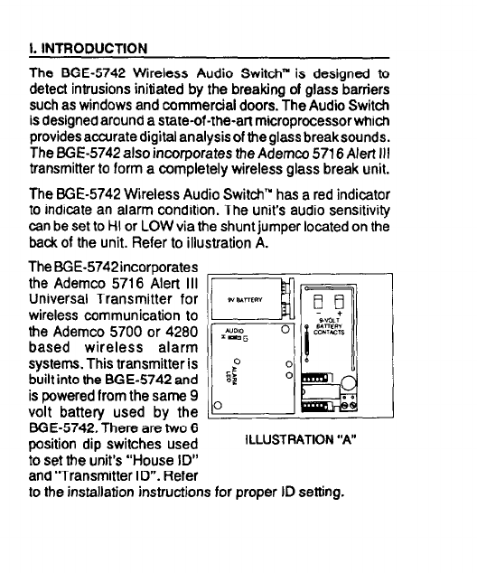
The BGE-5742 Wireless Audio Switch” has a red indicator
to indicate an alarm condition. The unit’s audio sensitivity
can be set to HI or LOW via the shunt jumper located on the
back of the unit. Refer to illustration A.
The BGE-5742incorporates
the Ademco 5716 Alert Ill v
Universal Transmitter for
wireless communication to
the Ademco 5700 or 4280
based wireless alarm
systems. This transmitter is
built into the BGE-5742 and
is powered from the same 9
volt battery used by the
BGE-5742.-There are-two 6
oosition dio switches used
ILLUSTRATION “A”
1
J
to set the unit’s “House ID”
and ‘Transmitter ID”. Refer
to the installation instructions for proper ID setting.

II. INSTALLATION
1. LOCATION:The BGE-5742 may be located on theceiling
just above the glass barrier to be protected, on the same
wall, on an opposite wall, or an adjacent wall. The Wireless
AudioSwitch’” should be located with an open field between
the unit and points of entry; no partitions, walls, furniture,
etc. should be between the unit and the glass to be protected.
The unit must be located within a 15 foot radius of the glass
being protected. Refer to illustration B. If the BGE-5742 is
mounted within 7 feet of the glass to be protected, the
sensitivity should be set to “LOW”. When the BGE-5742 is
mounted on the same wall, all sensitivity distances should
be reduced by 50%.
In choosing a location, it is important to keep in mind the
transmission path of the 5716 wireless transmitter. A good
transmission pathshould beestablished beforepermanently
installing the BGE-5742.
ILLUSTRATION “6”

2. TESTING: The installer should afways ensure proper
operation of the BGE-5742 after locating the unit. Testing
of the unit should be done
to ensure good audio
reception at the desired
mounting location. The
BGS-III Simulator, shown
in illustration C, should be
used to test the BGE-5742.
To test the BGE-5742, aim
the simulator at the glass
break detector while
holding it near the furthest
glass to be protected.
Activate the simulator by
pressing the button on the
top of the simulator. The
BGE-5742 should go into
alarm if the glass is within
its protection range. The
BGS-III is very directional
and must be aimed directly ILLUSTRATION“c”
at the BGE-5742.
When installation and testing procedures are completed,
activate any devices such as; air compressors, large fans,
blowers, etc. that may generate background noise while
the system is armed. For proper operation, devices that
generate background noise should not cause the unit to go
into alann. Ifthis condition results, relocate the unit to a new
position where the noise from these sources are minimized.
If the unit has been moved it must be retested with the BGS-
Ill Simulatorand again checked fortroublesome background
noise. Ifa position cannot be found tosatisfy these conditions,
and the sources of troublesome noise cannot be minimized
or eliminated, then the BGE-5742 is not suited for that
application.
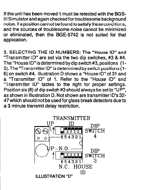
3. SELECTING THE ID NUMBERS: The “House ID” and
‘Transmitter ID” are set via the two dip switches, #3 & #4.
The”House ID”isdetermined bydipswitch#3, positions (l-
S).The“TransmitterID”isdetermined byswitchpositions(l-
6) on switch #4. Illustration D shows a “House ID” of 31 and
a “Transmitter ID” of 1. Refer to the “House ID” and
“Transmitter ID” tables to the right for proper settings.
Position six(6) of dip switch #3 should always be set to “UP”,
as shown in Illustration D. Not shown are transmitter ID’s 32-
47 which should not be used for glass break detectors due to
a 3 minute transmit delay restriction.
TRANSMITTER
I
N.C. HOUSE
ID
ILLUSTRATION “D”
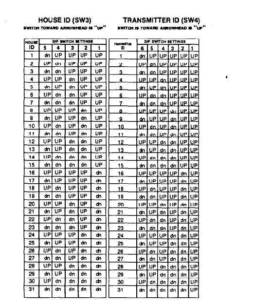
HOUSE ID (SW3) TRANSMITTER ID (SW4)
*wo4 low*no A”noWleADII “V” *ma, I¶,ow*RI AmowwuD. “I#*
_ , -. ,-, , -.
3 [ dnIdn[UP
4 1 UP/ UP 1 dn
-iiT
“P!dn!i#ic’“!
UP
UP
UP
UP
UP
UP
i
UP
UP
UP
UP
UP
UP
up
19 I &I dn IUPIUP I ti II 19 IdnldnlUPiUPldnlUP
‘2-J 1 UPIUPI dn IUP 1 * 11 20 lUPlUP[dnjUPldnlUP
[M-I ;: dnjUPIdn]UP[dnIUP
:UPldn!dnlUPldnlUP~
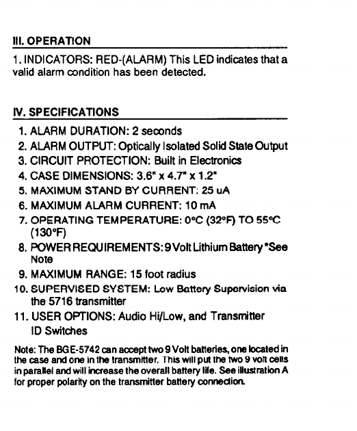
III. OPERATION
1. INDICATORS: RED-(ALARM) This LED indicates that a
valid alarm condition has been detected.
L
IV. SPECIFICATIONS
1. ALARM DURATION: 2 seconds
2. ALARM OUTPUT: Optically Isolated Solid State
Output
3. CIRCUIT PROTECTION: Built in Electronics
4. CASE DIMENSIONS: 3.6” x 4.7” x 1.2”
5. MAXIMUM STAND BY CURRENT: 25 uA
6. MAXIMUM ALARM CURRENT: 10 mA
7. OPERATING TEMPERATURE: 0°C (32°F) TO 55°C
(139°F)
8. POWER REQUIREMENTS: 9Voft Lithium Battery ‘See
Note
9. MAXIMUM RANGE: 15 foot radius
10. SUPERVISED SYSTEM: Low Battery Supervision via
the 5716 transmitter
11. USER OPTIONS: Audio Hi/Low, and Transmitter
ID Switches
Note: The EIGE-5742 can accept W 9 Volt batteries, ona localed in
the case and one in the transmitter. Thii will
putthe two 9 volt
cells
in paralel and will increase the overall battery tile. See iUustraIion A
for proper polarity on the transmitter battery cOnnedion.

V. APPLlCATlON AND MOUNTING TABLES
TYPE OF GLASS PROTECTED
l/8” and l/4” Plate Glass
l/4” Tempered Glass
l/4” Laminated Glass
114’Wired Glass
SENSOR LOCATIONS
Location Recommended
Same wall as glass Yes
Adjoining wall Yes
Opposite wall Yes
Ceilings-Structural (Fixed) Yes
Acoustical Yes
Drop Tile Yes
Maximum Range 15’
MOUNTING SURFACE
Surface Recommended
Dtywall/sheetrock Yes
Metal Yes
Brick Yes
Concrete block Yes
Poured concrete Yes
Wood Yes

TO THE INSTALLER
Regularmaintenance by the installer and frequenttesting
by the user are vital to maintain proper operation of any
alarm system.
NOTE: The BGE-5742 should be tested at least once a
year by theinstaller.
Theinstallershouldassumethe responsibiliiofdeveloping
andofferinga regular maintenance program to theuser as
well asacquaintingthe user with the proper operationand
liiticns of the alarm system and its component perts.
Recommendatior~smustbelndudedforaspedficprogram
of frequenttesting to insure the system’s pmper operation
at all times.
WARRANTY
You SGE-5742 Wireless Audio Switch- is wammted folaperbd
of24 monlhr from the date ol
purchaseagainstdefectivematertats
andwokmans&. Themanuladureragreestoreplan,
defective
materialsandrepaIrdalectlveworkmanshipwhk+~b
discovered
durlrg the aforesaid 24 month period, and this remedy is rxduske
cl all others including Incidental or
mnsequentlaldamages
Th&
wamdy Is in lieu d atl others inckiii spedfkdiy the watwnias
cdrnarkelabllityandfitness
for a padicular
purpose.
I
‘FEDERAL
COMMUNICATIONS COMMlSStON
(FCC) STATEMENT’
llm mar shall not make any changes or modkatbns to the
aqdpmetl unbss aulhodzed by the Installation lnstruabnsor
User’sManual.
lJna&iorized changes or mcdiikationscoukl
void the u&s authority to operate the equipmenl.

Popular Security System manuals by other brands

Anodyne Electronics Manufacturing
Anodyne Electronics Manufacturing AA37 Series Installation and operation manual

Chamberlain
Chamberlain LC-36A Addendum

Aico
Aico Ei3030 instruction manual

CMX
CMX EVAC-500 Installation and operation manual

Dantel
Dantel B18-05725-03 Installation & operation manual

Benewake
Benewake TFmini Plus product manual

Radionics
Radionics Security System 8112 user guide

NEC
NEC SL101-10 user manual

SECURELY
SECURELY S4i PERS user guide

Digital Monitoring Products
Digital Monitoring Products XR40 Security Command Executive Series user guide

IBM
IBM SP 4001 Disk Drive Assembly Replacement Instructions

Blue by ADT
Blue by ADT S40LR0-01 Setup guide


