Blue Ice BLUI-150A User manual
ver.201701_01
Installation and User’s Manual
I512A-023
BLUI-150A
BLUI-250A

Freight Claim Procedure (IMPORTANT)
1.
Specifications ........................................................................................... 4
1.1Technical Specification
1.2 Product Dimensions
1.3 Accessories Included in the Machine
1.4 Nameplate Format
2. Installation & Operation Guide ............................................................... 7
2.1
IMPORTANT : Before Installation
2.1.1 Installation Requirements
2.1.2 Location
2.2 Electrical Requirements
2.3 Water Supply & Drain Connections
2.3.1 Water Supply
2.3.2 Water Supply Line
2.3.3 Drainage Line
2.4 Final Check
2.5Test Run
2.6 Operation
2.6.1 Button
2.6.2 Status Light
2.6.3 7-segment
2.7 Operation Cycle
2.8 Safety
2.9 Error Code
3. Maintenance & Cleaning ....................................................................... 16
3.1 Maintenance
3.2 [BLUI-150A] Interior Cleaning & Sanitizing Procedure
3.3 [BLUI-150A] Product Disassembly
3.4 [BLUI-250A] Interior Cleaning & Sanitizing Procedure
3.5 [BLUI-250A] Product Disassembly
3.6 Exterior Cleaning
3.7 Accessories & Parts Cleaning
3.8 How to prepare for long time storage
Table of Contents
23

Freight Claims Procedure(Important)
23
Inspect Promptly
This product has been carefully inspected and packed in accordance with the
carrier’s packing specifications. Responsibility for safe delivery has been
assumed by the carrier. If loss or damage occurs, you as the consignee must file
a claim with the carrier and hold the container for carrier’s inspection.
Visible Loss or Damage
Any external evidence of loss or damage must be fully described and noted on
your freight bill or express receipt and signed by the carrier’s agent.The claim
should be filed on a form available from the carrier.
Concealed Loss or Damage
Concealed loss or damage should be reported to the carrier and vendor within 24
hours after delivery.
After this time the seller is not responsible for any freight damage incurred.
Keep the product as well as all of original packaging material in receiving area for
carrier's inspection.
1. Specifications
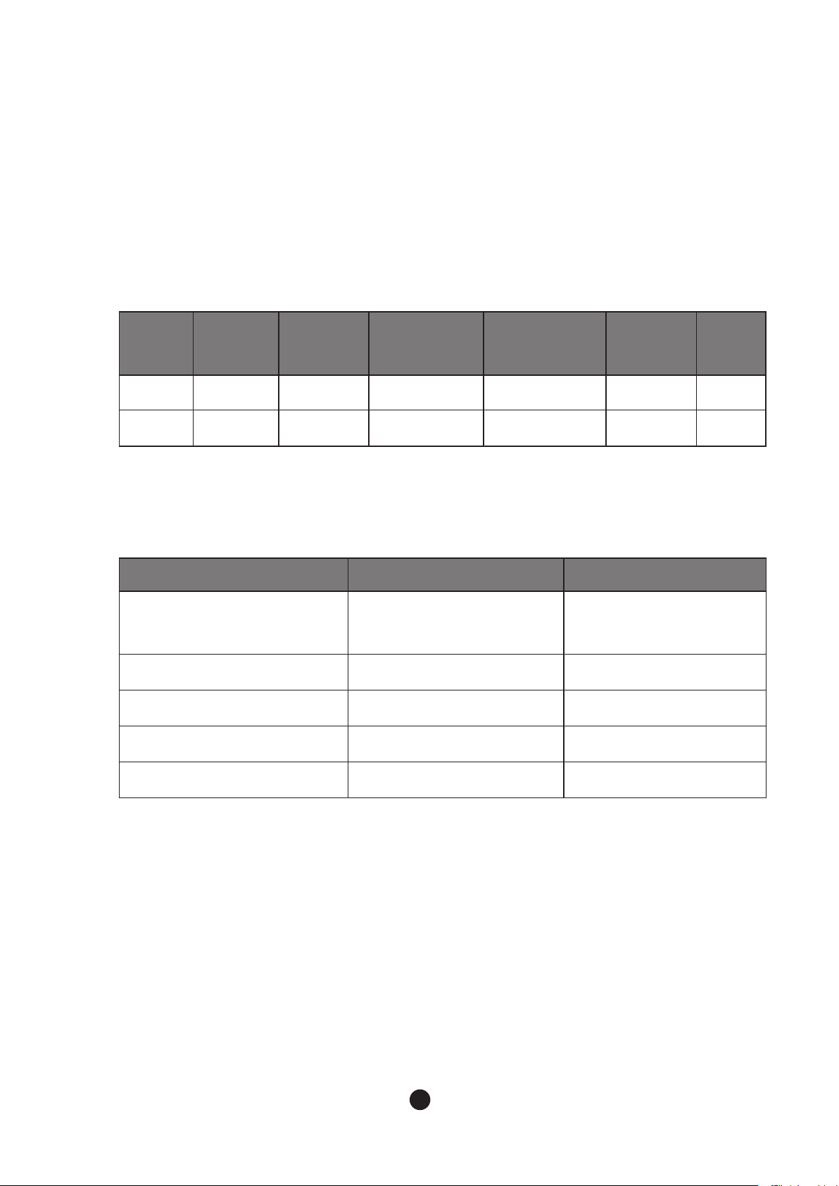
1.1 Technical Specification
Model Total AMPs Condenser
Maximum Fuse/
Circuit Breaker Rating Maximum
Current
Energy
Star
BLUI-150A 7.0A Air Cooling 15A 115V/60Hz/1Ph 7.5A Certified
BLUI-250A 8.3A Air Cooling 15A 115-120V/60Hz/1Ph 9.5A Certified
BLUI-150A BLUI-250A
Design Pressure
HI - 220 psig
LOW - 105 psig
HI - 460 psig
LOW - 210 psig
Refrigerant R-134a (8.46 OZ) R-404A (15.9 OZ)
Compressor 98-132V 28.0LRA 5.6RLA 103-127V 39.7LRA 7.6RLA
Pump 115V 0.50FLA 33.4W 115V 0.93FLA 57.5W
Fan 115V 0.53FLA 59.6W 115V 0.53FLA 59.6W
45
● Electrical Data
● Refrigerant Data
CONTENTS1. Specifications
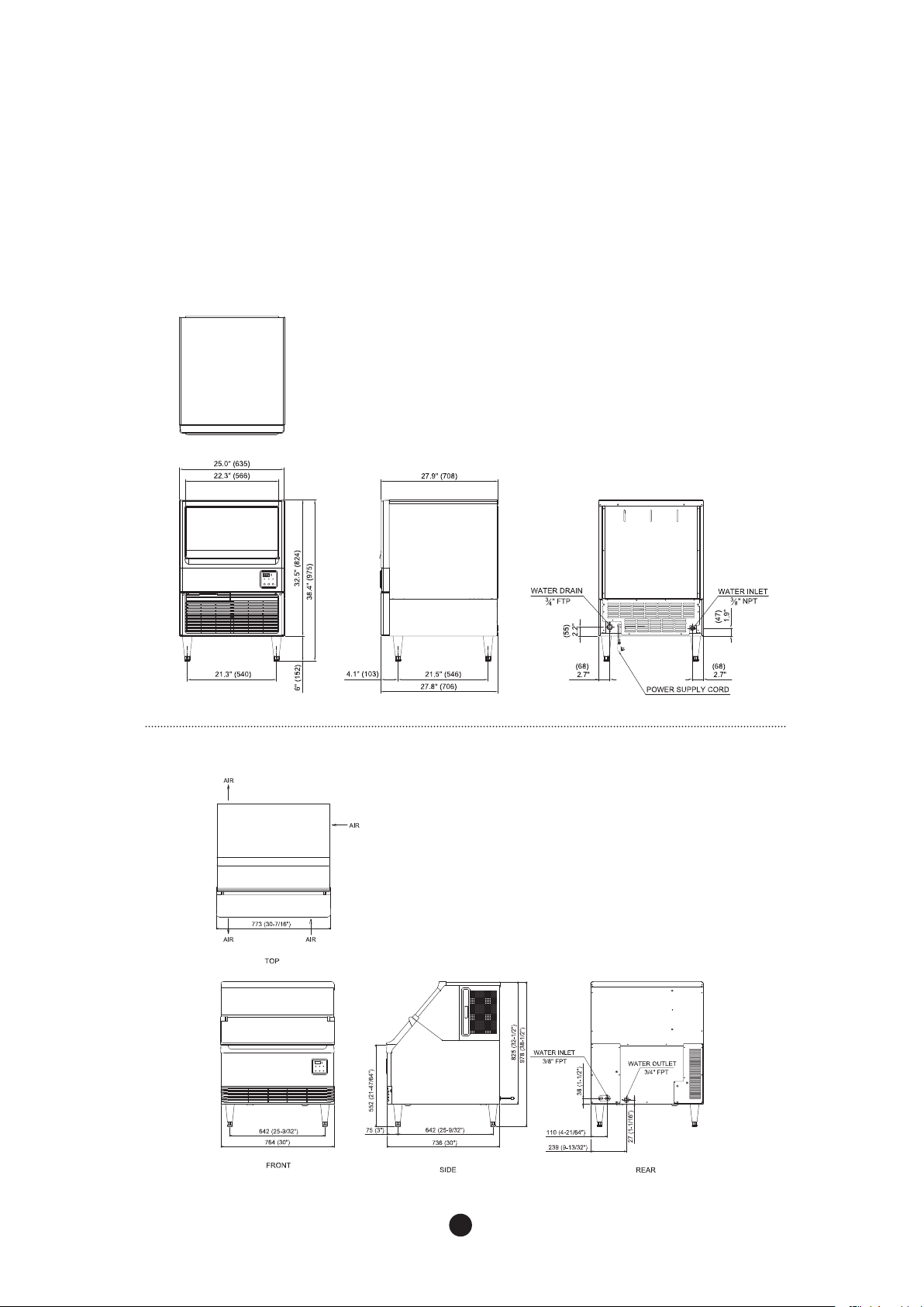
1.2 Product Dimensions
45
● BLUI-150A
● BLUI-250A
67
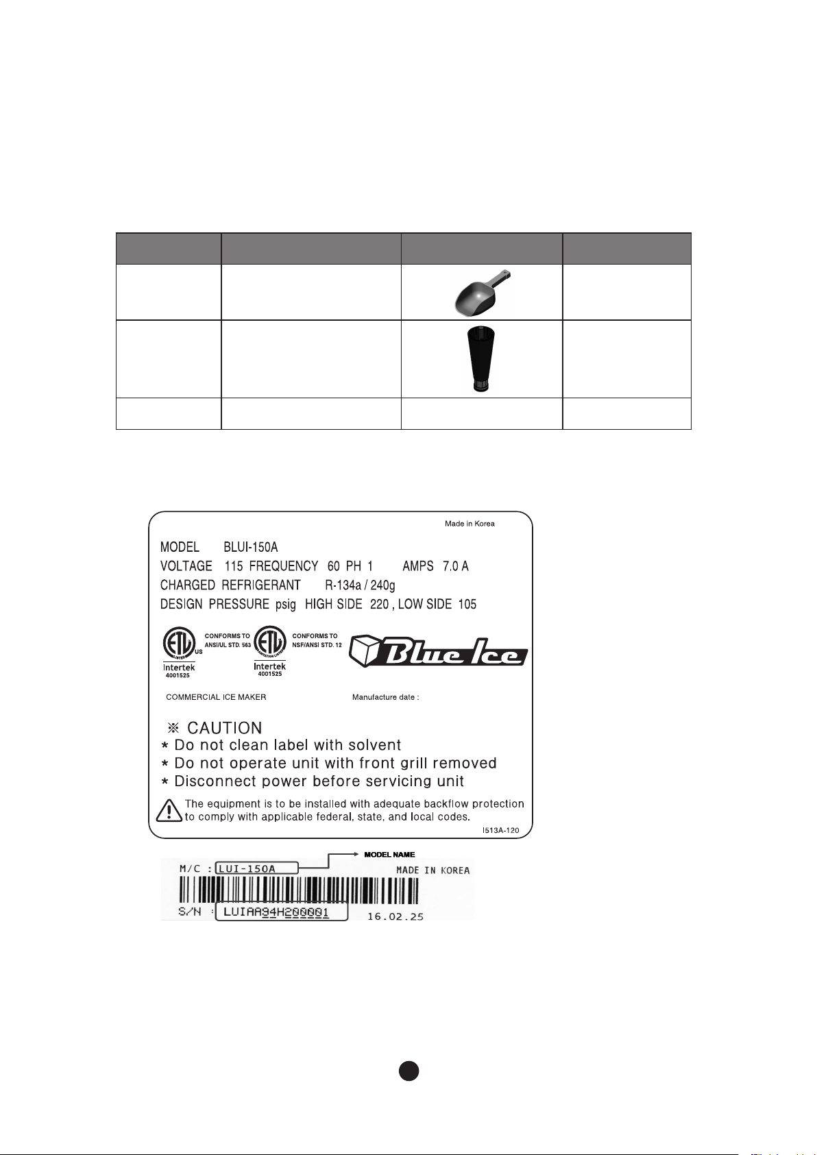
1.3 Accessories Included in the Machine
1.4 Nameplate Format
No Name Picture Quantity
1 Scoop 1
2Legs
6"(150 ~ 176 mm) 4
3 User Manual 1
See the Nameplate for electrical and refrigeration specifications.
This Nameplate is located on the upper part of the Left Side Panel.
We reserve the right to make changes in specifications and design without prior notice.
67
2. Installation & Operation Guide
2.1 IMPORTANT: Before Installation
2.1.1 Installation Requirements
2.1.2 Location
Condition Minimum Maximum
AmbientTemperature
°F 45 100
°C 7 38
WaterTemperature
°F 45 90
°C 7 32
Voltage V 100 130
Water Pressure psig 30
100
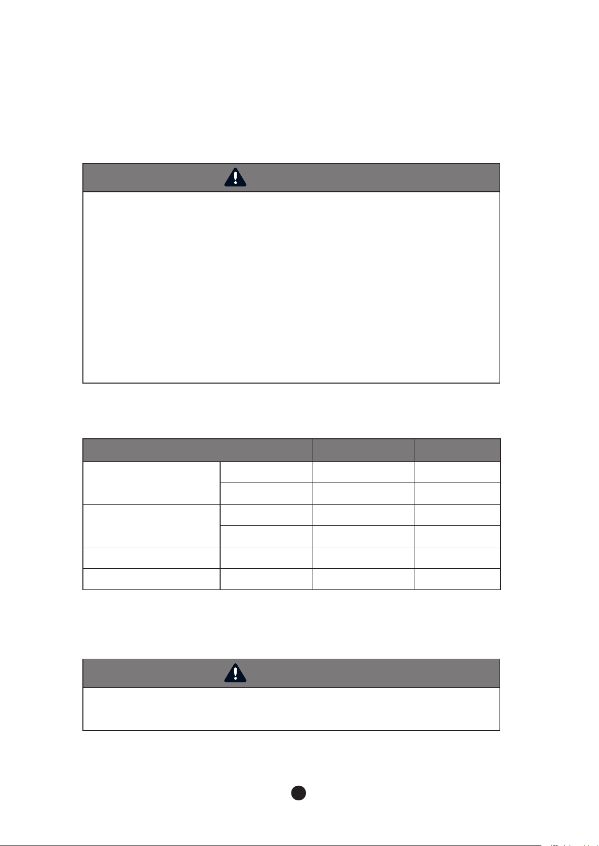
WARNING
Our qualified service technicians can only install the product. Likewise, the owner/manager
should not proceed to operate the product until the installer instructs them on its proper use.
Failures to install, operate, and maintain the equipment in accordance with this manual may
adversely affect safety, performance, components’ life, and warranty coverage.The warranty
statement for this product is provided separately from this manual.
In general, warranty covers defects in material or workmanship. It does not cover
maintenance, corrections to installations, or situations when the machine is operated in
circumstances that exceed the limitations printed below.
* Power should be off when installing an ice machine.
*The marking “CAUTION or WARNING - Parts. Do Not Operate Unit With Enclosure
Removed.” (When disassembly for cleaning or similar servicing exposes moving parts
WARNING
Do not put heavy objects over 33 lbs(15kg) on top of the machine. It will need at least 39
inches (1 meter) for service.
89
CONTENTS
-The icemaker is designed for indoor use only.
- Level the icemaker from side to side and front to rear by adjusting the legs.
Location should provide a firm and level foundation for the machine.
-The icemaker should not be located next to ovens, grills, or other high heat producing equipment.
-The legs must be installed before starting the machine.
- After installation, make sure that all the components, fasteners, and screws are all fixed in proper
positions. Check if any of them fell into the storage container.
Please read the following cautions;
-The Icemaker must have the earthwork done.
-The Icemaker must have exchangeable fuse or circuit breaker.
- Decide the appropriate size of the wire based on the length, thickness, and position of the wires.
- Above work has to be done by a qualified electrical engineer.
NOTE : The icemaker requires no clearance at either side. But allow approximately 5” (12cm)
at rear for water supply and drain connections.
2.2 Electrical Requirements
WARNING
- All kinds of power wiring work including power cable connection and earth have to be done
in accordance to the law and regulations of the Country, State, and District.
-The earthwork for icemaker has to be done in accordance to the law and regulations of the
Country, State, and District.
● Voltage
- When operating the icemaker (with maximized electrical load) range of variation in maximum
voltage allowed is +10%/-5% of the rate voltage.
- Specification of the power cord when released from the factory is 6.5’ (2.0m) with NEMA 5-15P Plug.
● Fuse/Circuit Breaker
- Must have the exclusive fuse/circuit breaker for the icemaker.
- As for circuit breaker, US HACR (Heating, Air Conditioning, and Refrigeration) type must be used.
● TOTAL CIRCUIT AMPACITY
- For details about size of cable for power supply, please refer to the “1.1Technical Specification.”

89
In the place where icemaker is installed, it may require an additional processing system to
prevent formation of scale and removing impurities and chlorine for the water quality side.
Please refer to the following instructions for installing water supply line.
- Do not connect hot water system to the icemaker.
- Appropriate water pressure is 30 ~ 100 psig.
- Install shut-off valve to the water supply line.
- Insulate the water supply line to prevent condensation.
To prevent backflow of icemaker and storage container, please refer to the following instructions
for installing drainage line.
- For the smooth drainage, gradient of 1 inch for every 5’ (2.5cm per meter) is needed.
- Do not install any trap.
- Do not connect drainage pipe directly into the sewage pipe.
-There must be minimum 2’’ of air gap vertically between end of drainage pipe and the
drain hole.
- Must install vent.
2.3 Water Supply & Drain Connections
2.3.1 Water Supply
2.3.2 Water Supply Line
2.3.3 Drainage Line
WARNING
- Installation of water supply and pipe system has to be done in accordance to the law and
regulation of the Country, State, and District.
-The icemaker is to be installed with adequate backflow protection to comply with applicable
federal, state, and local codes.
- Water pipe work has to be done by qualified service technicians.

10 11
● BLUI-150A
Floor
* Leave a 2”(5 cm) vertical air gap between the end of each pipe and the drain.
Vent tube
Minimum 3 ⁄4:”
ID Hard pipe
Shut- Off
Valve
Floor
Water supply
inlet - 3/8”FPT
Drain Valve
Drain Outlet
- 3 ⁄ 4” FPT
Minimum 1/4”
ID copper pipe
Shut- Off
Valve
Drain Outlet
- 3 ⁄ 4” FPT
Minimum 1/ 4”
ID copper pipe
Water supply
inlet - 3/ 8”FPT
Vent tube
Drain Valve
● BLUI-250A
Minimum 3/ 4
ID Hard pipe
Floor
10 11
2.4 Final Check
2.5 Test Run
WARNING
After installation, make sure that all the components, fixture, and thumbscrews are tightly in
their places. Make sure that no impurities fall into the ice storage container.
WARNING
Icemaker is factory-adjusted. In general, no additional setting is required after installing the
product. In case of random modification, it may cause adverse influence on safety, function,
component lifespan, and warranty period. Warranty is not included in the setting and
maintenance process explained in this manual.
(1) Is ambient temperature of the installation area within the allowed range (45 ~ 100°F)?
(2) Is temperature of water supplied in the installation area within the allowed range (45 ~ 90°F)?
(3) Are all the packing materials such as packing box, inside tape, and other materials removed
completely?
(4) Is there an enough clearance from the icemaker for smooth air circulation?
(5) Is ice scoop placed in the right place?
(6) Is icemaker leveled on the floor?
(7) Is the product located indoor?
(8) Is the power supply to the icemaker installed properly?
(9) Is water supply pipe to the product properly connected?
(10)Is drain system properly connected?
(11)Is water pressure qualified (30 ~100 psig)?
(12)Any leakage found in any pipes?
(13)Are all the components, fixtures, and thumbscrew fixed tightly?
(14)Have you informed to the customers about the product manual, how to use, and interval for
changing main components?
(15)Have you provided information on selling points and A/S center to the customer?
(1) Open the shut off valve in the water supply system.
(2) Press "POWER" button for 2 seconds to operate the icemaker.
(3) Water tank is filled with water through the water supply valve.
(4) After water is filled, it turns into harvesting cycle and control board shows “2.00.”
(5) After this, it turns into freezing cycle and control board shows “3.00.”
(6) About 3 minutes after freezing cycle, press “POWER” button for 2 seconds to stop the machine.
(7) ①LUI-150A :Disconnect’ Hose Drain Joint’ connected to‘ WaterTank’ to drain remaining water.
② LUI-250A :Push ‘WASH’ button to drain remaining water.
(8) ①LUI-150A : Reconnect ‘Hose Drain Joint’ once remaining water is completely drained.
② LUI-250A :Turn off the machine when ‘Add’ is appeared on the control panel.
(9) Press “WASH”button to release water inside the water tank.
(10) Unplug the power cord.
(11) Open the door and clean inside of the ice storage inside with neutral detergent.
(12) Wash thoroughly after cleansing.
(13) Operate the machine and check any leakage inside and outside the pipes.
12 13
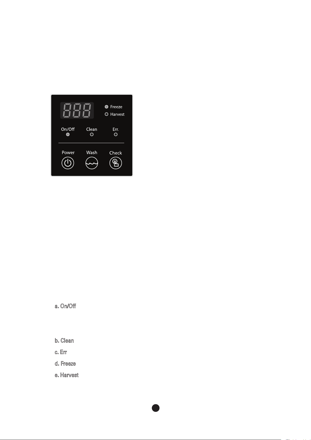
2.6 Operation
2.6.2 Status Light
2.6.1 Button
1) Power
Push the button for 2 seconds to turn on/off.
2) Wash
Use the button when cleaning the machine. Refer to the
'cleaning' label on the left side of the machine.
3) Check
Only for service persons to check status of the machine
a. On/Off : shows power status in green.
If storage container is full of ice, it shows brown light.
If too low, it will show red light.
b. Clean : show green light when in washing mode.
c. Err : show red light if any problems occur during the machine operation.
d. Freeze : shows green light when freezing cycle in operation.
e. Harvest : shows orange light when ice harvesting cycle is in operation.
12 13
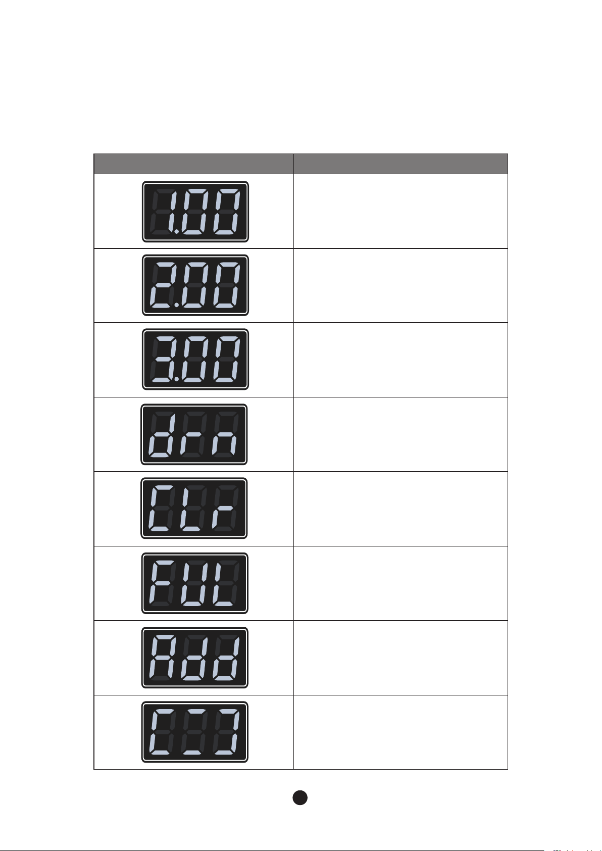
Display Status
1 = Water Supply Period
.00 = Elapsed time (x 10 sec)
2 = Harvesting Period
.00 = Elapsed time (min)
3 = Freezing Period
.00 = Elapsed time (min)
Drainage cycle
Wash mode
Shown when wash button is pressed.
Shown when the bin is full of ice.
During wash mode
Showing input timing or detergent or sanitizer
Cleaning and saitization completed
(User has to press the button to remove
this sign)
2.6.3 7– segment

14 15
Icemaker is operated in accordance to the following process
2.7 Operation Cycle
2.8 Safety
(1) Water Supplying Cycle
Once power is on, water supply valve opens to fill the water tank with water required.
(2) Harvesting Cycle
To remove ice made on the evaporator, water flow stops and it becomes hot. Then, ice is released from
the evaporator to storage container. Once temperature sensor detects a certain temperature, freezing
cycle begins. Water is continued to be supplied during the harvesting cycle.
(3) Freezing Cycle
This is the process of making an ice. Water is supplied to the surface of evaporator and it becomes cold.
As water keep circulating, more and more iceis made. This process is repeated until water level sensor
reaches low. Once it becomes the low level, ice harvesting starts.
(4) Drainage Cycle
This occurs residue or impurities in the water tank while repeating the process of freezing and
harvesting cycles. Using ice machine for a long time without any drain may cause damage.
After a certain number of cycles, drain leftover water in the water tank completely by using pump.
(1) Maximum freezing time - 60min
To protect the icemaker, maximum freezing time is set to 60 minutes. When freezing cycle goes over 60
minutes, it turns into harvesting cycle. Also for the second freezing cycle, if time goes over 60 minutes,
machine halts and shows error code (E1) on the control panel with a beep sound.
(2) Maximum harvesting time - 20min
The maximum harvesting time is 20 minutes. If time goes over 20 minutes, it automatically turns into
freezing cycle. Also in the second harvesting cycle, if time goes over 20 minutes, error code (E2) is
shown on the control panel with a beep sound.
(3) HighTemperature safety
If temperature outside the evaporator during freezing cycles goes over 140°F(60°C), machine stops to
protect the cycle and error code (E3) is shown on the control panel.
(4) Low water safety
For protection of water pump, if water level is low after harvesting cycle, machine halts and error code (E5)
is shown on the control panel.

14 15
Code Problem Possible Cause Remarks
E1
Freezingerror
(freezing time
exceeds 60 min)
Refrigerant leaked or pipe blocked
Compressor not operating
Fan motor not operating
Ambient or water temperature too high A/T : 45
°F
~100
°F
(7
°C
~38
°C
)
W/T : 45
°F
~90
°F
(7
°C
~32
°C
)
Voltage : 100V ~130V
Voltage too high or too low
E2
Harvesting error
(harvesting time
exceeds 20 min)
Refrigerant leaked or pipe blocked
Compressor not operating
Hot gas valve not operating
Evaporator temperature sensing error
Ambient or water temperature too low A/T : 45
°F
~100
°F
(7
°C
~38
°C
)
W/T : 45
°F
~90
°F
(7
°C
~32
°C
)
Voltage : 100V~130V
Voltage too high or too low
E3
Evaporator
temp too high
(temp > 140
°F
or 60
°C
)
Water temperature too high W/T: 45
°F
~90
°F
(7
°C
~32
°C
)
Sensor or connector defect
PCB defect
E5
Water supply not
enough
(water supply
time exceeds 4
min)
Float switch not operating
Water valve not operating
Water pressure too low
W/P: 30psi~100psi
E6
Evaporator
sensor error Sensor short-circuit or disconnected
E7
PCB error PCB program error
2.9 Error Code

3. Maintenance & Cleaning
●
Maintenance Period
Please refer to the following table for guidance on Maintenance Period. It may be shorter
depending on surrounding environment and hygiene regulations of the installation area.
16 17
3.1 Maintenance
WARNING
Icemaker shall be maintained and cleaned based on this manual and cleaning label attached on
each unit
Interval Part Method
Daily Scoop Clean scoop with neutral detergent. Wash thoroughly
after cleaning.
Every two weeks
Air Filter
If dirty, clean with warm water by using detergent.
Every month
Exterior water
supply filer
Check the appropriate water supply and change the filter if
necessary.
Icemaker exterior Wipe out dirty exterior part by applying neutral detergent onto
the soft cloth.
Storage bin & Door Wipe out with a soft cloth.
Every six months
Icemaker
Storage bin
Wash and sanitize in accordance to the manual.
Please refer to the "3.2/3.3 cleaning and sanitizing."
Water supply area Close the water supply valve and drain all the water inside.
Condenser
Check dust or impurities first. If necessary, clean using brush or
vacuum. Cleaning interval may be shorter depending on the
surrounding environment.
Water drain Check water drain inside the icemaker and clean or replace if
necessary.

16 17
3.2 [BLUI-150A] Interior Cleaning & Sanitizing Procedure
WARNING
- Please use a detergent and sterilizer, according to directions of the product. sanitizer for ice
machines, and follow directions of those products.
- During cleaning and sanitizing, please wear rubber gloves and protective eye glasses to
protect eyes and skin.
- Please keep a detergent and sterilizer out of the reach of small children.
- Please do not remove ices, made on evaporator, by force. It might cause damage to the
surface of evaporator.
Please do not remove ices on evaporator with a sharp ice pick.
1)Turn off the ice maker. If ices are being made, wait for cycle completion and then turn off the ice maker.
2) Remove all remaining ices in the storage.
3) Prepare 10 liters of cleaning solution by diluting 1 pack(56.7g/2 Oz) of Kay-Delimer with 4 liters of warm water.
4) Contact the distributor of ice maker to purchase cleaning solution [Kay - Delimer]
5) Press the “WASH” button.
6) Remaining water in the storage is drained and “drn” appears on the control board.
7) Once drainage is completed, “Add” will appear on the control board.
8) Pour 4 liters of cleaning solution from procedure 3) into the water tank.
(The next operation is automatically performed after 60 seconds)
9) “Crn” will appear on the control board after a minute.
10)The water pump drains the water after 30 minutes of operation.
11) After drainage, water will be supplied for 3 minutes.
12)The water pump operates for 5 minutes to remove the remaining cleaning solution.
13)The water is drained after 5 minutes washing procedure.
14)The ice maker repeats step 11 to step 13 three times for 30 minutes.
15) After 30 minutes operation, appears on the control board and Power turns off.
16) Disassemble hose and water tank referring to step 4 ~ 6 on 150 Product Disassembly
(All parts of ice maker has to be disassembled and cleaned referring to step 1 ~ 10 on 150 Product
Disassembly at least once every six months.)
Fig 1 Fig 2
The icemaker should be cleaned and sanitized every six months. Depending on the water
quality of the installation place, it could be done more often.
(1) Cleaning Procedure

18 19
(2) Sanitizing Procedure
1) Prepare 10 liters of cleaning solution by diluting 1 pack(28.4g/1 Oz) of Kay-5sanitizer with 9.5 liters of
warm water.
2) Contact the distributor of ice maker to purchase sanitizing solution [Kay -5 (Sanitizer)]
3) Soak the separated parts while cleaning procedure into the 6 liters of sanitizing solution for 5 minutes.
4) Sanitize ice maker and food zone of storage container by using spray.
5) Wait until the sanitized parts are dried.
6) Reassemble the separated parts after cleaning.
7) Press “WASH” button then “Add” will appear on the control board.
8) Pour 4 liters of sanitizing solution from procedure 1) into the water tank.
9) “Crn” will appear on the control board after a minute.
10)The water pump drains the water after 30 minutes of operation.
11) After drainage, water will be supplied for 3 minutes.
12)The water pump operates for 5 minutes to remove remaining sanitizing solution.
13)The water is drained after 5 minutes washing procedure.
14)The ice maker repeats step 12 to step 14 three times for 30 minutes.
15) After 30 minutes operation, appears on the control board and Power turns off.
16)Turn on the power to start freezing.
8IZ\Q\QWV
M^IXWZI\WZ4. 8IZ\Q\QWV
M^IXWZI\WZ:0
*ZIKSM\
M^IXWZI\WZ4.
*ZIKSM\
M^IXWZI\WZ:0
?I\MZX]UX
/]QLMQKM
?I\MZ\IVS
.TWI\[_Q\KP
) )
Guide ice
Water tank
Fig 3 Fig 4
※ice machine cleaner & sanitizer has to comply with 40 CFR §180.9403 or registered with the USEPA
Office of Pesticides Program, Antimicrobials Division as a food contact ice machine cleaner & sanitizer.
17) Wash disassembled parts with 6 liters of cleaning solution from 3).
Only use nylon brush (Not wire brush), sponge and soft cloth to brush the parts. (Dishwashing liquid also can be
18) Wash storage out with clean water and dry the storage.

18 19
3.3 [BLUI-150A] Product Disassembly
1. Unscrew two screws on the back side of top cover then pull the top cover out to disassemble it
referring to above image.
2. Lift the door up through the groove to disassemble it referring to above image.
Top Cover
Door
Screw

20 21
3. Unscrew two screws on the Partition Top Cover and lift it up to disassemble it referring to above
image.
4. Detach Bracket Inner Cabi from the evaporator referring to above image.
Screw
PartitionTop Cover
Bracket lnner Cabi
This manual suits for next models
1
Table of contents
Popular Ice Maker manuals by other brands


Scotsman
Scotsman DCE33 Series Service bulletin

Moosoo
Moosoo YT-E-005A instruction manual

Hoshizaki
Hoshizaki CUBELET ICEMAKER/DISPENSER DCM-750BAH-OS parts list

Hoshizaki
Hoshizaki KM-515MAH-E parts list

Hoshizaki
Hoshizaki SRK-15J instruction manual

Sunbeam
Sunbeam Avalanche IS6800 Instruction/recipe booklet


