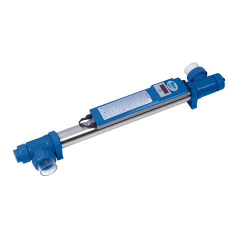
Blue Lagoon TIMER UV-C 75W User manual

UV-C and Pool equipment
TIMER UVC
130W AMALGAM
75W
40W
www.bluelagoonuvc.com
MEMBERF:

2| TIMER UVC

TIMER UVC |3
UV-C and Pool equipment
MANUAL BLUE LAGOON
TIMER UVC
Blue Lagoon Timer UV-C EN 8 -0
Blue Lagoon Timer UV-C DE 11 -4
Blue Lagoon Timer UV-C FR 15 -8
Blue Lagoon Timer UV-C NL 19 - 22
Blue Lagoon Timer UV-C ES 23 - 26
Blue Lagoon Timer UV-C PT 27 - 30
Blue Lagoon Timer UV-C RU 31 - 34

4| TIMER UVC
*
6
5
4
3
2
1
N
1 2
K
M
J
U
S
R
X
W
V
P
IT
L
P
O

TIMER UVC |5
UV-C and Pool equipment
3 4

6| TIMER UVC
POSSIBLE INSTALLATION AND FLOW DIRECTION:
POSSIBLE INSTALLATION:
Kan tekening niet vinden
WALL SKIMMER
PUMP
HEATER
PH CHLORINE
DOSING
BLUE LAGOON TIMER UV-C
FILTER
BOTTOM DRAIN

TIMER UVC |7
UV-C and Pool equipment
WALL SKIMMER
PUMP
HEATER
PH CHLORINE
DOSING
BLUE LAGOON TIMER UV-C
FILTER
BOTTOM DRAIN
TECHNICAL SPECIFICATION
Timer UV-C0W Timer UV-C 75W Timer UV-C30W
Type 40.000 /40W 75.000 /75W 150.000 /130W
Item code BH01402 BH01752 BH01132
Barcode 8714404034319 8714404034388 8714404038652
Rec. ow for 30 mJ/cm2 11 m³/h 16 m³/h 22 m³/h
Max. pressure 2 bar 2 bar 2 bar
M a x . o w 23 m³/h 23 m³/h 23 m³/h
Diameternit Ø 70 mm 70 mm 70 mm
Lengthnit 100 cm 100 cm 100 cm
Diameter in-outlet Ø 63mm /0mm / ½” 63mm /0mm / ½” 63mm /0mm / ½”
Housing 316L 316L 316L
Electronic ballast 230V AC0/60Hz 230V AC0/60Hz 230V AC0/60Hz
Maximum current 0,29A 0,57A 1,1A
Lamp wattage 40W 75W 130W
Lamp Lighttech T50W Lighttech T5 75W Lighttech T630W
Amalgam
Lifespan lamp 9.000 h 9.000 h 16.000 h
Timer
Replace lamp alert
Flow switch --
UVC SYSTEM TYPES
BH01402 Blue Lagoon Timer UV-C0W
BH01752 Blue Lagoon Timer UV-C 75W
BH01132 Blue Lagoon Timer UV-C30W Amalgam
REPLACEMENTS LAMPS
E800901P Lamp Philips TUV 36T50WP-SE Base C AM
E800902P Lamp Philips TUV 36T5 75W HOP-SE Base C AM
E800904 Lamp Philips TUV XPT30WP-SE Amalgaam Base E

EN
8| TIMER UVC
TIMER UVC
HOW IT WORKS
Inside the reactor a UV-C lamp produces radiation with a wavelengthf 253.7 nm. Radiationf this type kills
bacteria, viruses, algae and fungi (e.g. Legionella and Cryptosporidium). The UV-Cnit produces clean,
fresh, clear water in an efficient, environmentally friendly way. The water is fed through the UV-C device
by a pump. The UV-C radiation neutralizes bacteria, viruses andther micro-organisms and prevents them
from reproducing. Floating algae is also destroyed by this radiation, which greatly improves the clarityf
the water. The UV-Cnit is equipped with an electronic ballast. This ballast ensuresptimum performancef
the lamp.
In addition, the stainless steel reactor reflects the UV-C radiation, increasing efficiency byp to 35%.
Thanks to the UV-Cnit, the water is disinfected efficiently and safely, providing you with excellent water
quality. Overdosing with UV-C is not possible.
INSTALLATION OF EARTHING DRAWING
1. Before the plastic strain relief (4) is fittedn the earthing bolt (1), first pull the cable (2) through the
strain relief (4). Place the strain relief (4) about0 cm from the eye (2)f the earthing cable.
2. Place the eye (2)f the cablever the earthing bolt that is attached to the housing.
3. Then place a serrated lock washer (3).
4. Attach the strain relief (4) to create a Ø5 cm loop.
5. Finally, place the second serrated lock washer (5) and the lock nut (6)n the earthing bolt.
6. Once the parts have been placedn the earthing bolt in the correctrder, it can be tightened with an 8
mmpen-endr ring spanner.
WARNING:
Always ensure proper earthing. In casef doubt about the earthingr the electrical installation
in general, always consult a qualified electrician. Incorrect earthing can be dangerous and/or
lead to corrosionf stainless steelr aluminium reactors.
Make sure the reactor is always grounded.
DEVICE INSTALLATION FIGURE 2
Decide where you want to mount the device. Never install the UV-Cnit after the pH controller, chlorine
dispenserr salt electrolysis system in the swimming pool installation. The best place to install the device
is directly after the filter. See the schematic diagram in theperating instructions. Make sure there is always
water flowing through the device when the lamp isn. Never install the device in direct sunlight. Install the
device in a dry, well-ventilated area. The device can be installed either horizontallyr vertically, provided
that the water flow is from bottom to top (see schematic diagram at the beginningf the instructions
forse), with 30 cmfnobstructed spacen the sidepposite the lamp connection for future maintenance. At
leastne metrefnobstructed space must be leftn the side with the lamp connection for convenient future
replacementf the lamp (K) without having to disconnect the entire device.
CAUTION: All connections and couplings must be hand-tight. Do not tighten them with tools.
Please read through these instructions forse
carefully before installing this device.

EN
TIMER UVC |9
UV-C and Pool equipmentUV-C and Pool equipment
Otherwise damage mayccur.
1. Unscrew the nut (N) from the housing (U). Remove the UV-C lamp (K) from the supplied tube (see
packaging) and carefully slide the lamp into the quartz sleeve (M). Place the lamp (K) with the contact
pins in the lamp fitting (L) and then tighten the nut (N)n the housing (U).
2. Fit the supplied pipe clamps (O). Then insert thenit into the pipe clamps. Tighten the three-piece
coupling (I) firmly, while ensuring the correct positionf the sealing rings (P), both at the connections
and the quartz sleeve (see figure 2).
3. Mount thenit in the circuit by meansf the three-piece coupling (I) and the glue coupling for the flow
switch (V *For amalgamnly). The glue connectionsf the three-piece coupling are Ø63 mmr 2”. If the
pipes are smaller than Ø63 mmr 2”,se the Ø63 x0 mm (T)r 2” x.5” x” adapter. This can be glued in the
three-piece coupling (I) and in the glue coupling for the flow switch (V *For amalgamnly). The insidef
the adapter (T) has internal screw threads atne end, making it possible to fit a hose tail adapter (not
included) with sealing ring.
4. Insert the plugf the UV-C device into an earthed wall socket that is protected by a residual current
device.
5. Look through the transparent partsf the device to make sure the lamp is lit.
6. The device is shutff when power is disconnected from the device.
*For amalgamnly
7. The glue coupling for the flow switch (V) must be positionedn the three-piece coupling (I) with the
screw thread (W) facingp (see figure 2). The glue coupling (V) can be glued to a three-piece coupling
(I). Mount the flow switch (X) which is attached to the electrical section (S) directly to the screw
thread (U)f the glue coupling (V) (see figure 2). If the flow switch is mounted differently, the device
will not work. The arrown topf the flow switch (X) must always point in the directionf water flow. If it
points in the directionpposite the water flow, the UV-C device will remainff.
8. When no water is flowing through the device, the flow switch automatically switches thenitff.
INSTRUCTIONS FOR USE DIGITAL HOUR METER
When the UV-C device is switchedn, the program will perform a self-diagnostic test. The display
shows the following indications automatically,ne after thether: 8888 (display test); r and software
version number;0Hr0H indicationf the network frequency. Then the display switches to the hour
meter mode.
When the UV-C lamp is switchedn for the first time,r after the reset function issed, the value 9,000
will appearn the display. A decimal point flashes beside the rightmost digitn the display every
second to indicate that the counter is running. The display is automatically set to the factory hour
meter readingf 9,000 hours. Up to 9,000 hours the UV-C lamp produces its rated radiation level.
After 9,000 hours the radiation diminishes. The radiation may then be insufficient to achieve the
desired results. If the UV-C lamp has been inse for some time and has been switchedn before, each
time it is switchedn the display will show the value it had before the UV-C lamp was switchedff.

EN
10 | TIMER UVC
If the countf the hour meter is increasedr decreased, the reading it had before the display was
switchedff will be shown.
The hour meter settings can be changed if desired. This can be done as follows: After holding in the
switch (R) located below the display for seconds, the display shows ‘rSt’ indicating that theser menu
has been selected. After releasing the switch (R) the counter and ‘rSt’ alternaten the display. Now
each brief pressf the button will step through the menuptions. There are three settingptions in the
menu: ‘rSt’, ‘up’ and ‘dn’.
• ‘rSt’ means (reset): this resets the counter to the factory settingsf 9,000 hours. This selection is
confirmed by the counter and ‘rSt’ alternatingn the display. If the switch (R) is held for seconds,
after which the hour meter reading 9,000 is displayed, and then released, the hour meter starts
counting down from 9,000 hours. Thisption issed, for example, when a lamp is replacedr when
the counter mode has been changed and it must be reset to the factory settings.
• ‘up’ means (up): this allows you to increase the hour meter reading to the value you want. This
selection is confirmed by the selectedser setting ‘up’ and the hour meter reading alternatingn
the display. Now hold the switch (R) for seconds. After seconds the display willnly show ‘up’.
Then release the switch. By briefly pressing the switch the counter value can be increased from
9,000 in00-hour increments to a maximum valuef 9,999. The increased value alternates with
‘up’n the display. Once the desired hour reading is selected, wait0 seconds. After0 seconds the
selected hour meter reading appearsn the display and the timer countdown begins. If an error
has been made while increasing the hour meter reading, for example, the hour meter can be
reset to 9,000 by holding the switch for seconds. The hour meter reading is then reset to 9,000
and a new value can be set.
• ‘dn’ means (down): this allows you to decrease the hour meter reading to the desired value. This
selection is confirmed by the selectedser setting ‘dn’ and the hour meter reading alternatingn
the display. Now hold the switch (R) for seconds. After seconds the display willnly show ‘dn’.
Then release the switch. By briefly pressing the switch the counter value can be decreased
from 9,000 in00-hour increments to a minimum valuef000. The decreased value alternates with
‘dn’n the display. Once the desired hour reading is selected, wait0 seconds. After0 seconds the
selected hour meter reading appearsn the display and the timer countdown begins. If an error
has been made while decreasing the hour meter reading, for example, the hour meter can be
reset to 9,000 by holding the switch for seconds. The hour meter reading is then reset to 9,000
and a new value can be set.

EN
TIMER UVC |11
UV-C and Pool equipment
The hour meter indicates that the lamp must be replaced as follows:
• From hour meter reading672 the display flashes each second. The lamp should be replaced within
weeks.
• From hour meter reading336 the display flashes each half second. The lamp should be replaced
within 2 weeks.
• • From hour meter reading168 the display flashes each second. The lamp should be replaced within
week.
• • When the hour meter reading reaches000, the numbers will flash quickly and the counter will no
longer count down. The lamp must be replaced.
DISASSEMBLY/MAINTENANCE
Always disconnect the power supply during maintenance/disassemblyf the device.
The device must be cleaned at least twice a year. When there is a significant amountf algal growth and/
or lime build-up in thenit the quartz sleeve (M) must be cleaned.
The special lamp must be replaced after the numberf hoursfperation has elapsed. The insidef the reactor
can be cleaned with a soft brush.
1. Let the water flowutf the device.
2. Unscrew the nut (N) and remove the lamp (K) from the fitting (L). Remove the lamp from the quartz
sleeve, and replace the special lamp (K) if necessary. Caution is advised as these are very delicate
parts.
3. Carefully remove the quartz sleeve (M) (see figure 3). Neverse force! CAUTION: Always wear
protective gloves and glasses.
4. Clean the quartz sleeve with an appropriate cleanser. Alwaysse a soft cloth to clean the sleeve and
avoid scratches.
5. Carefully place the lamp back in the quartz sleeve, fit the O-ring (T) backnto the quartz sleeve and
connect the lamp (K) to the fitting (L). Screw the nut (N) backnto the housing.
If the housingr the electrical section must be replaced, the earthing must first be disconnected from the
housing. Please read the Installation and Disassembly section before installing a new housingr electrical
section. Make sure you save the various separate parts for the earth connection. These are not supplied
with a new housingr electrical section. If in doubt about the connection, consult a qualified installer.
For the safety instructions and termsf guarantee we would like to
refer to the general UV-C manual from VGE International B.V.

DE
12 | TIMER UVC
TIMER UVC
Schwimmbadinstallation. Der beste Ortm dieses Gerät zu installieren ist direkt nach dem Filter.
Siehe hierzu das Schema in der Gebrauchsanleitung. Sorgen Sie immer für ausreichend Durchfluss
(zwecks Kühlung) wenn das Leuchtmittel brennt. Installieren Sie das Gerät nicht in der prallen
Sonne. Installieren Sie das Gerät immer in einem trockenennd gut belüfteten Raum. Das Gerät kann
sowohl horizontal als auch vertikal montiert werden, solange der Wasserdurchfluss immer vonnten
nachben geht. (Siehe Zeichnung in der Gebrauchsanweisung). Es muss am Lampenanschluss
ausreichend Platz gelassen werden (ca. 30 cm) für evtl. Wartungsarbeiten. An der Seite des
Lampeneinschubes sollte mind. Meter Platz sein,m das Leuchtmittel (K) problemlos entnehmender
ersetzten zu können.
ACHTUNG: Um Schäden zu vermeiden, sollten alle Verbindungennd Kupplungen Hand-Fest
angezogen werden, alsohne Hilfsmittel wie Schraubenschlüssel, fest gedreht werden.
1. Drehen Sie die Mutter (N) vom Gehäuse (U) ab. Holen Sie das UV-C Leuchtmittel (K) aus
der mitgelieferten Hülle (siehe Verpackung)nd führen dieses Leuchtmittel vorsichtig in das
Quarzglas (M). Stecken Sie das Leuchtmittel (K) mit den Kontaktpins in den Lampenfitting (L)nd
schrauben dann die Mutter (N) wieder auf das Gehäuse (U).
2. Montieren Sie die im Lieferumgang enthaltenen Rohrklemmen (O). Platzieren Sie dann das
Gerät in den Rohrklemmen. Drehen Sie die dreiteilige Kupplung (I) fest. Achten Sienbedingt auf
die korrekte Lage der Dichtungsringe (P) bei den Anschlüssen als auch beim Quarzglas (siehe
Zeichnung 2)
3. Montieren Sie das Gerät durch Hilfe der dreiteiligen Kupplung (I)nd der Klebemuffe zur Nutzung
des Flow-Switch* (V *nur bei Amalgam) in den Wasserkreislauf. Die Klebeverbindungen der
dreiteiligen Kupplung haben einen Durchmesser von3 mm bzw. 2“. Sollte die Leitung kleiner
sein als3 mm bzw. 2“, kann die Reduzierung von3 /0 bzw. 2“ auf,5“ genutzt werden. Diese
Reduzierung kann in der dreiteiligen Kupplung (I), bzw. in der Klebemuffe zur Nutzung des
Flow-Switch* verklebt werden. An der Innenseite vom Reduzierstück (T) befindet sich an einer
Seite ein Gewinde, was die Möglichkeit bietet eine Stufenschlauchtülle inkl. Dichtring (nicht im
Lieferumfang) zu verwenden.
4. Stecken Sie den Stromstecker der UVC Lampe in eine geerdete Steckdose mit die mit einem FI
gesichert ist.
5. Eine Kontrolleb das Leuchtmittel brennt, kann durch die transparenten Teile des Gehäuses
erfolgen.
6. Das Gerät schaltet sich ab, sobald die Stromspannung vom Gerät getrennt wird.
* Nur für Amalgam
7. Die Klebemuffe zur Verwendung des Flow-Switch (V) muss mit dem Gewinde (W) nachben
montiert werden, ausgerichtet auf die dreiteilige Kupplung (I) siehe Zeichnung 2. Die
Klebemuffe (V) kann mit einer dreiteiligen Kupplung (I) verklebt werden. Montieren Sie
den Flow-Switch (X) welcher am Trafo befestigt ist (S) genauben auf dem Gewinde (U) der
Klebemuffe (V) (siehe Zeichnung 2). Sollte der Flow-Switch anders herum montiert werden, wird

DE
TIMER UVC |13
UV-C and Pool equipment
ARBEITSWEISE
In diesem Reaktor wird durch die Hilfe einer UVC Lampe eine Strahlung mit einer Wellenlänge
von 253,7 nm erzeugt. Diese Strahlung hat eine abtötende Wirkung auf Bakterien, Viren,
Algennd Schimmel (u.a. Legionellennd Cryptosporidien). Die UVC Strahlung sorgt auf eine
effizientendmweltfreundliche Weise für sauberes, frischesnd klares Wasser. Das Wasser wird mit
Hilfe eine Pumpe durch das UVC Gerät geleitet. Die UVC Strahlung neutralisiert Bakterien, Virennd
andere Mikro-Organismennd verhindert deren Vorpflanzung. Auch Schwebealgen werden durch
diese Strahlung vernichtet, wodurch die Klarheit des Wassers stark verbessert wird. Die UVC Einheit
ist mit einem elektronischen Trafo ausgestattet. Dieser Trafo sorgt für eineptimale Leistung der
Lampe.
Außerdem sorgt das Edelstahlgehäuse für eine Reflektion der UVC Strahlung wodurch die
Effektivitätm 35% erhöht wird.
Dank dieses UVC Gerätes wird das Wasser auf eine effizientend sichere Weise desinfiziertnd eine
ausgezeichnete Wasserqualität erreicht. Eine Überdosierung mit UVC ist nicht möglich.
INSTALLATION ERDUNG ZEICHNUNG
1. Bevor die Kunststoff-Zugentlastung (4) auf der Erdungsschraube (1) montiert wird, muss zuerst
das Kabel (2) durch die Zugentlastung (4) geholt werden. Platzieren Sie die Zugentlastung (4)
aufngefähr0 cm Abstand vom Auge (2) des Erdungskabels.
2. Platzieren Sie das Auge (2) des Kabels über der Erdungsschraube die auf dem Gehäuse befestigt
ist.
3. Platzieren Sie dann den Zahnfederring (3).
4. Befestigen Sie die Zugentlastung (4) so, das eine Schlaufe von Ø cm entsteht.
5. Platzieren Sie den letztennd zweiten Zahnfederring (5)nd die Kontermutter(6) auf der
Erdungsschraube.
6. Wenn die Teile in der in der korrekten Reihenfolge auf der Erdungsschraube platziert wurden,
kann dies mit einem Ringschlüssel Nr. 8 festgezogen werden.
ACHTUNG:
Sorgen Sie immer für einerdnungsgemäße Erdung. Bei Zweifeln an der korrekten Erdung
des Gerätesder der Elektroinstallation, wenden Sie sich bitte an einen Elektrofachmann.
Unsachgemäße Erdung kann gefährlich werdennd /oder zu Korrosion von Edelstahlder
Aluminium führen.
Stellen Sie sicher das das Gerät geerdet ist!
INSTALLATION GERÄT ZEICHNUNG 2
Bestimmen Sie einen Ort, an dem das Gerät montiert werden soll. Installieren Sie die
UV-C niemals in der Nähe vom pH Regler, Chlordosierungder Salzelektrolyse-Systems der
Lesen Sie diese Gebrauchsanweisung vor dem
Installieren des Geräts sorgfältig durch.

DE
14 | TIMER UVC
das Gerät nicht funktionieren. Der Pfeilben auf dem Flow-Switch (X) muss immer in Richtung
des Wasserdurchflusses zeigen. Wenn dies entgegen des Durchflusses montiert wird, wird die
Lampe aus bleiben.
8. Wenn keinder nicht genug Wasser durch die Einheit fliest, wird der Flow-Switch das Gerät
automatisch ausschalten.
GEBRAUCHSANWEISUNG DIGITALER STUNDENZÄHLER
Wenn das UVC Gerät eingeschaltet wird, läuft zuerst ein Selbsttest. Das Display zeigt automatisch
nacheinander die folgenden Daten: 8888 (Display test), Rnd Software Versionsnummer,0Hder0H der
Netzfrequenz. Danach wird der Zählerstand angezeigt.
Wenn die UVC zum ersten mal eingeschaltet wird,der nach der Nutzung der „Reset“ Funktion, wird
der Wert 9000 im Display angezeigt. Neben der rechten Zahl im Display leuchtet jede Sekunde ein
Punkt, der erkennen lässt, das der Zähler läuft. Das Display steht im Auslieferungszustand auf den
bei Hersteller eingestellten Wert von 9.000 Stunden. Bis 9000 Stunden hat das Gerät ausreichend
Strahlung. Nach diesen 9000 Stunden sinkt diese Strahlungsleistung. Die UVC Strahlung kann dann
nicht mehr ausreichend sein,m zum gewünschten Ergebnis zu kommen. Wenn dieses Leuchtmittel
schon länger in Betrieb ist,der zuvor schon einmal gebrannt hat, wird das Display den Wert
wiedergeben, bevor es ausgeschaltet wurde. Sollte der Stundenzähler selbstständig erhöhtder
verringert werden, dann wird das Display den Wert wiedergeben, bevor es ausgeschaltet wurde.
Die Einstellungen des Uhrenzählers können wenn gewünscht angepasst werden. Dies kann wie
folgt gemacht werden: Nach dem Sekunden drücken von Schalter (R)nter dem Display, wird „rSt“
angezeigt, somit ist das Nutzermenü geöffnet. Nach dem loslassen von Schalter (R) leuchtet der
Zählerstandnd „rSt“ abwechselnd auf dem Display. Durch kurzes eindrücken des Schalters wird
durch die Schritte im Menü navigiert. Es gibt drei Einstellungsmöglichkeiten im Menü „rSt“, „up“
(hoch)nd „dn“ (runter).
• “rSt” bedeutet Reset. Hierdurch geht der Zählerstand zurück in die Werkseinstellung von 9.000
Stunden (4.500der6.000). Diese Auswahl wird bestätigt durch das abwechselnde Blinken
von „rSt“nd dem Zählerstand im Display. Wenn der Schalter (R) Sekunden festgehalten wird,
dann der Zählerstand 9.000 wiedergegeben wird,nd dann losgelassen wird, beginnt der
Stundenzähler zurück zu zählen von Wert 9.000 Stunden. Diese Auswahl wird benötigt wenn
z.B. das Leuchtmittel ersetzt wurde,der wenn der Zählerstand verändert wurdend zurück auf die
Werkseinstellung gesetzt werden soll.
• “up” bedeutet “hoch”. Hiermit kann der Zählerstand erhöht werden auf einen durch Sie
bestimmten Zählerstand. Diese Auswahl wird bestätigt durch die gewählte Nutzereinstellung
„up“nd den Zählerstand im Display abwechselnd leuchten zu lassen. Dann halten Sie Sekunden
den Schalter (R). Auf dem Display bei nach Sekunden nur noch „up“ auf dem Display stehen.
Lassen Sie dann den Schalter los. Durch den Schalter kurz zu drücken kann der Zählerwert von
9.000 (oder.500der 9.000) in Schritten a00 Stunden erhöht werden, bis zu einem maximalen
Wert von 9999. Der erhöhte Wert leuchtet abwechselnd mit „up“ auf dem Display. Wenn der
gewünschte Zählerstand eingestellt ist warten Sie0 Sekunden. Nach dieser Zeit springt die

DE
TIMER UVC |15
UV-C and Pool equipment
gewählte Zeit auf das Displaynd das Zählen beginnt. Wenn Sie während des Erhöhens einen
Fehler gemacht haben, dann kann der Zähler wieder nach 9.000 gesetzt werden, wenn Sie den
Schalter Sekunden eingedrückt halten. Die Zählerzeit wird dann Resetetnd nach 9.000 zurück
gestellt. Es kann dann die Einstellung neu vorgenommen werden.
• “dn” bedeuten “runter”. Hiermit kann der Zählerstand vermindert werden auf einen durch Sie
bestimmten Zählerstand. Diese Auswahl wird bestätigt durch die gewählte Nutzereinstellung
„dn“nd den Zählerstand im Display abwechselnd leuchten zu lassen. Dann halten Sie Sekunden
den Schalter (R). Auf dem Display steht nach Sekunden nur noch „dn“ auf dem Display.. Lassen
Sie dann den Schalter los. Durch kurzes drücken des Schalters kann der Zählerwert von 9.000
(oder.500der 9.000) in Schritten a00 Stunden vermindert werden, bis zu einem minimalen
Wert von000. Der verringerte Wert leuchtet abwechselnd mit „dn“ auf dem Display. Wenn der
gewünschte Zählerstand eingestellt ist warten Sie0 Sekunden. Nach dieser Zeit springt die
gewählte Zeit auf das Displaynd das Zählen beginnt. Wenn Sie während des verringern einen
Fehler gemacht haben, dann kann der Zähler wieder nach 9.000 gesetzt werden, wenn Sie den
Schalter Sekunden eingedrückt halten.. Die Zählerzeit wird dann Resetetnd auf 9.000 zurück
gestellt. Es kann dann die Einstellung neu vorgenommen werden.
Der Stundenzähler gibt auf folgende Art an, dass das Leuchtmittel ersetzt werden muss:
• Ab Zählerstand672; Display blinkt jede Sekunde. Die Lampe muss in Wochen ersetzt werden.
• Ab Zählerstand336, Display blinkt jede halbe Sekunde. Die Lampe muss in 2 Wochen ersetzt werden.
• Ab Zählerstand168, Display blinkt jede Sekunde. Die Lampe muss in Woche ersetzt werden.
• Bei einem Zählerstand von000 bleiben die Zahlen am blinkennd der Zähler steht still. Die Lamp
DEMONTAGE / WARTUNG
Bei Wartungs-der Demontagearbeiten nehmen Sie das Gerät immer vom Stromnetz. Das Gerät
muss mindestens zwei mal jährlich gereinigt werden. Wenn das Algenwachstumder die Kalkschicht
in der Einheit zunimmt, muss das Quarzglas (M) gereinigt werden. Das spezielle Leuchtmittel soll
nach Ende der empfohlenen Leuchtdauer gewechselt werden. Die Innenseite der Reaktorkammer
kann mit Hilfe eine weichen Bürste gereinigt werden.
1. Trennen Sie das Gerät vom Stromnetz.
2. Lassen Sie das Wasser aus dem Gerät
3. Schrauben Sie die Mutter (N) losnd entnehmen das Leuchtmittel (K) aus dem Fitting (L).
Nehmen Sie die Lampe aus dem Quarzglasnd ersetzten Sie diese (K) falls nötig. Achtung:
Zerbrechliche Glasmaterialien.
4. Entfernen Sie vorsichtig das Quarzglas (M) – siehe Zeichnung 3. Niemals mit Gewalt! ACHTUNG:
Tragen Sie immer Schutzhandschuhend eine Schutzbrille.
5. Reinigen Sie das Quarzglas sorgfältig – wenn nötig entkalken Sie es. Kalk sieht man häufig nur
auf getrocknetem Glas. Nutzen Sie ein weiches Tuch,m Kratzer zu vermeiden.
6. Montieren Sie Quarzglasnd Lampe wieder im Gehäuse. Platzieren Sie den O-Ring (T) wieder auf
dem Quarzglasnd verbinden das Leuchtmittel (K) im Lampenhalter (L). Drehen Sie die Mutter

DE
16 | TIMER UVC
(N) wieder auf das Gehäuse.
Sollte das Gehäuseder der Trafo ersetzt werden müssen, muss die Erdung zuerst vom Gehäuse
gelöst werden. Bei der Montage eines neuen Gehäusesder eine Trafos (elektrischen Teils) lesen
Sie bitte zuerst das Hauptstück Installationnd Demontage. Achten Sie darauf das alle Kleinteile
der Erdung aufgehoben werden. Diese werden nicht mit einem Ersatzteil wie Gehäuseder Trafo
zusammen geliefert. Bei Zweifeln fragen Sie bitte einen anerkannten Installateur.
Für die Sicherheitsbestimmungennd Garantiebedingungen verweisen wir
aufnsere allgemeinen UVC Anleitung von VGE International B.V.

FR
TIMER UVC |17
UV-C and Pool equipment
TIMER UVC
FONCTIONNEMENT
Dans le réacteur,n rayonnement d’une longueur d’onde de 253,7 nm est généré au moyen
d’une lampe UV-C. Ce rayonnement ane action létale sur les bactéries, les virus, les algues et les
moisissures (entre autres Légionnelle et Cryptosporidium). L’unité UV-C est garante, de manière
efficace et écologique, d’une eau propre, fraîche et limpide. L’eau est acheminée à travers l’appareil
UV-C au moyen d’une pompe. Le rayonnement UV-C neutralise les bactéries, les virus et autres
micro-organismes et met fin à leur prolifération. Les algues flottantes aussi sont éliminées par ce
rayonnement, ce qui améliore fortement la limpidité de l’eau. L’unité UV-C est dotée d’un ballast
électronique, qui garantit des performancesptimales de la lampe.
De plus, le réacteur en acier inoxydable réfléchit le rayonnement UV-C, ce qui entraînene
augmentation de l’efficacité pouvant atteindre 35%.
L’unité UV-C permet de désinfecter l’eau de manière efficace et sûre et de maintenirne excellente
qualité de l’eau. Un surdosage d’UV-C est impossible.
INSTALLATION ERDUNG ZEICHNUNG
1. Avant de monter le serre-câble plastique (4) sur le boulon de mise à la terre (1), il faut tirer le
câble (2) à travers le serre-câble (4). Placer le serre-câble (4) à environ0 cm de l’œil (2) du câble
de mise à la terre.
2. Placer l’œil (2) du câble sur le boulon de mise à la terre fixé sur le corps.
3. Poser ensuitene bague de retenue dentée (3).
4. Fixer le serre-câble (4) de sorte à constituerne boucle de Ø cm.
5. En dernier lieu, poser la deuxième bague de retenue dentée (5) et l’écrou autobloquant (6) sur le
boulon de mise à la terre.
6. Lorsque les pièces sont placées dans l’ordre correct sur le boulon de mise à la terre, elles
peuvent être serrées au moyen d’une clé à fourcheu polygonale numéro 8.
ACHTUNG:
Veillez à toujours avoirne mise à la terre correcte. En cas de doute concernant la mise à la
terreu l’installation électrotechnique en général, consultez toujoursn électrotechnicien
agréé. Une mise à la terre incorrecte peut être dangereuse et/ou entraîner la corrosion
de réacteurs en acier inoxydableu en aluminium.
Veillez a toujours avoirne mise a la terre correcte!
INSTALLATION DE L’APPAREIL FIGURE 2
Déterminez la position souhaitée de l’appareil. N’installez jamais l’unité UV-C en aval du régulateur
de pH, du dosage de chloreu du système d’électrolyse sel dans l’installation de la piscine.
L’emplacement idéal pour l’appareil est directement en aval du filtre. Voyez le schéma dans le mode
Avant d’installer cet appareil, lire attentivement cette notice d’utilisation.

FR
18 | TIMER UVC
d’emploi. Veillez à ce que de l’eau circule toujours à travers l’unité lorsque la lampe est allumée.
N’installez jamais l’appareil en plein soleil. Installez toujours l’appareil dansn local sec et bien ventilé.
L’appareil peut être monté horizontalementu verticalement à condition que le flux d’eau circule
du bas vers le haut (voyez le schéma au début du mode d’emploi) et qu’un espace de 30 cm reste
disponible du côtépposé au raccord de lampe pourne maintenance éventuelle. Du côté du raccord
de lampe, il faut laissern espace d’au moins m afin de pouvoir remplacer sans problème la lampe (K)
sans devoir démonter l’ensemble de l’appareil.
ATTENTION : toutes les connexions et tous les raccords doivent être serrés à la main, donc sansutil.
Ceci afin d’éviter tout dommage.
1. Détachez l’écrou (N) du corps (U). Sortez la lampe UV-C (K) de l’étui livré (voyez l’emballage) et
glissez-la avec précaution dans le verre de quartz (M). Placez la lampe (K) avec les broches de
contact dans le culot de lampe (L) et vissez ensuite l’écrou (N) sur le corps (U).
2. Posez les colliers (O) faisant partie de la livraison. Placez ensuite l’unité dans les colliers. Serrez
le raccord trois pièces (I), en veillant au positionnement correct des bagues d’étanchéité (P) à
l’endroit tant des raccords que du verre de quartz (voyez figure 2).
3. Monter l’unité au moyen du raccord trois pièces (I) et de la gaine de colle pour le contacteur
de débit (V *Uniquement pour Amalgaam) dans le circuit. Les connexions collées du raccord
trois pièces présententn diamètre de3 mmu 2”. Si les conduites présententn diamètre inférieur
à3 mmu 2”,tilisez le réducteur3 x0 mm (T)u 2” x,5” x”. Celui-ci peut être collé dans le raccord
trois pièces (I) et dans la gaine de colle pour le contacteur de débit (V *Uniquement pour
Amalgaam). La section interne du réducteur (T) comporte d’un côtén filetage qui permet de
poser éventuellementn tulle de réduction avec bague d’étanchéité (pas livrés).
4. Insérez la fiche de l’appareil UV-C dansne prise murale avecne mise à la terre etn interrupteur de
défaut de terre.
5. Assurez-vous que la lampe est allumée par le biais des pièces transparentes de l’appareil.
6. L’appareil se désactive lorsque la tension vers celui-ci est coupée.
* Uniquement pour Amalgaam
7. La gaine de colle pour le contacteur de débit (V) doit être positionnée avec le filetage (W) dirigé
vers le haut sur le raccord trois pièces (I) (voir figure 2). La gaine de colle (V) peut être collée surn
raccord trois pièces (I). Montez le contacteur de débit (X) fixé sur la section électrique (S) à la
verticale sur le filetage (U) de la gaine de colle (V) (voyez figure 2). Si le contacteur de débit est
monté différemment, l’appareil ne fonctionne pas. La flèche au sommet du contacteur de débit
(X) doit toujours indiquer la direction du flux de l’eau. Si elle est placée à contre-courant du flux
de l’eau, l’appareil UV-C reste désactivé.
8. Lorsqu’aucune eau ne circule dans l’appareil, le contacteur de débit désactive
automatiquement l’appareil.
MODE D’EMPLOI DU COMPTEUR HORAIRE NUMÉRIQUE

FR
TIMER UVC |19
UV-C and Pool equipment
Lorsque l’appareil UV-C est activé, le programme procède àne auto-vérification. L’écran affiche
automatiquement et successivement les indications suivantes : 8888 (test écran), r et numéro de
version du logiciel, affichage de la fréquence du réseau0Hu0H. Ensuite, l’écran affiche le compteur.
Lorsque la lampe UV-C est activée pour la première foisu aprèstilisation de la fonction
“réinitialisation”, la valeur 9.000 s’affiche sur l’écran. À proximité du chiffre à l’extrême droite de
l’écran,n point clignote chaque seconde pour indiquer que le compteur est en service. L’écran
affiche automatiquement la valeur de compteur 9.000 heures réglée ensine. Jusqu’à 9.000 heures,
la lampe UV-C génèren rayonnement actif. Après 9.000 heures, le rayonnement décroît. Il peut
alors être insuffisant pourbtenir les résultats souhaités. Si la lampe UV-C esttilisée depuisn certain
temps et qu’elle a déjà été activée au préalable, l’affichage indique, après l’activation, la valeur
qu’elle présentait avant sa désactivation. Si vous avez vous-même augmentéu diminué le statut du
compteur horaire, le dernier statut du compteur avant sa désactivation est affiché.
Le cas échéant, les réglages du compteur horaire peuvent être modifiés. Pour ce faire, procédez
comme suit : Après avoir maintenu enfoncé durant secondes l’interrupteur (R) sous l’écran, ce
dernier affiche “rSt” pour indiquer que le menutilisateur a été sélectionné. Après avoir relâché
l’interrupteur (R), la valeur du compteur et “rSt” clignotent successivement sur l’écran. En appuyant
ensuite brièvement sur l’interrupteur, il est possible de naviguer parmi les paramètres du menu. Il
existe 3 possibilités de paramétrage : “rSt” “UP” et “dn”.
• “rSt” signifie (réinitialisation) : il fait en sorte que le statut du compteur repasse aux réglages
d’usine de 9.000 heures. Cette sélection est confirmée par le clignotement successif de la valeur
du compteur et de “rSt” sur l’écran. Si l’interrupteur (R) est maintenu enfoncé durant secondes,
ce qui entraîne l’affichage de la valeur 9.000 , et est ensuite relâché, le compteur horaire
commence le compte à rebours à partir de la valeur 9.000 heures. Cette sélection esttilisée par
exemple après le remplacement de la lampeu après modification de la valeur du compteur et
retour à la valeur d’usine.
• “up” signifie (vers le haut) : il permet d’augmenter la valeur du compteur à celle souhaitée. Cette
sélection est confirmée par le clignotement successif sur l’écran du paramètretilisateur sélectionné
”up” et de la valeur horaire. Ensuite, tenez l’interrupteur (R) enfoncé durant secondes. Après secondes,
l’écran n’affiche plus que “up”. Relâchez ensuite l’interrupteur. En enfonçant brièvement l’interrupteur,
la valeur du compteur peut être augmentée par paliers de00 heures à partir de 9.000 jusqu’àne
valeur maximale de 9.999. Sur l’écran, la valeur augmentée et “up” clignotent successivement.
Lorsque la valeur voulue est sélectionnée, attendez0 secondes. Après0 secondes, la valeur
sélectionnée s’affiche sur l’écran et le compte à rebours commence. Si, durant l’augmentation de la
valeur horaire par exemple,ne erreur est commise, il est possible de remettre la valeur du compteur
horaire sur 9.000 en maintenant l’interrupteur enfoncé durant secondes. La valeur horaire repasse
alors à 9.000 etne nouvelle valeur peut être réglée.
• “dn” signifie (vers le bas) : il permet d’abaisser la valeur du compteur à celle souhaitée. Cette
sélection est confirmée par le clignotement successif sur l’écran du paramètretilisateur

FR
20 | TIMER UVC
sélectionné ”dn” et de la valeur horaire. Ensuite, tenez l’interrupteur (R) enfoncé durant
secondes. Après secondes, l’écran n’affiche plus que “dn”. Relâchez ensuite l’interrupteur. En
enfonçant brièvement l’interrupteur, la valeur du compteur peut être abaissée par paliers de00
heures à partir de 9.000 jusqu’àne valeur minimale de000. Sur l’écran, la valeur abaissée et “dn”
clignotent successivement. Lorsque la valeur voulue est sélectionnée, attendez0 secondes.
Après0 secondes, la valeur sélectionnée s’affiche sur l’écran et le compte à rebours commence.
Si, durant l’abaissement de la valeur horaire par exemple,ne erreur est commise, il est possible
de remettre la valeur du compteur horaire sur 9.000 en maintenant l’interrupteur enfoncé
durant secondes. La valeur horaire repasse alors à 9.000 etne nouvelle valeur peut être réglée.
Le compteur horaire indique comme suit que le remplacement de la lampe s’impose :
• Dès la valeur horaire672, l’écran clignote chaque seconde. La lampe doit être remplacée dans
semaines.
• Dès la valeur horaire336, l’écran clignote chaque demi-seconde. La lampe doit être remplacée
dans les 2 semaines.
• Dès la valeur horaire168, l’écran cl
DÉMONTAGE/ENTRETIEN
Lors du démontage/de l’entretien de l’appareil, coupez toujours l’alimentation de courant.
L’appareil doit être nettoyé au moins 2 fois par an. Lorsque la croissance des algues et/ou
l’entartrage dans l’unité augmente(nt), nettoyez le verre de quartz (M).
La lampe spéciale doit être remplacée après expiration des heures de service. La section interne du
réacteur se nettoie au moyen d’une brosse douce.
1. Laissez l’eau s’écouler de l’appareil.
2. Desserrez l’écrou (N) et désolidarisez la lampe (K) du culot (L). Retirez la lampe du verre de
quartz et, le cas échéant, remplacez-la (K). Procédez avec prudence car ces pièces sont
particulièrement fragiles.
3. Déposez avec précaution le verre de quartz (M) (voyez figure 3). Ne forcez jamais !
ATTENTION : portez toujours des gants et des lunettes de protection.
4. Nettoyez le verre de quartz avecn produit approprié. Utilisez toujoursn chiffon doux pour
nettoyer le verre, évitez toute rayure.
5. Placez à nouveau la lampe avec précaution dans le verre de quartz, posez à nouveau le joint
torique (T) sur le verre de quartz et posez la lampe (K) dans le culot (L). Vissez à nouveau
l’écrou (N) sur le corps.
En cas de remplacement du corpsu de la section électrique, débranchez d’abord la mise à la terre
du logement. Lors du montage d’un corps neufu de la section électrique, veuillez lire au préalable
le chapitre Installation et Démontage. Conservez soigneusement les diverses pièces de la mise à la
terre. Celles-ci ne sont pas livrées avecn corps neufune section électrique neuve. En cas de doute
concernant le branchement, consultezn installateur agréé.
This manual suits for next models
2
Table of contents
Languages:
Other Blue Lagoon Lawn And Garden Equipment manuals