blue photon BlueCure Mini User manual

www.BluePhotonGrip.com • 855-777-20401002 Industrial Park Dr., Shelby, MI 49455
User GuideTechnology & Workholding Systems
®
Please read the user and operating guide carefully before using the controller. After reading, please keep this manual
handy so that you can refer to it at any time.
BlueCure Mini UV LED Controller
BlueCure mini spot curing system is for curing BlueGrip workholding adhesive.
Part # 65440 UV LED Controller, 4 Channel
Features
• 1-4 individual UV LED heads, interchangeable to any channel.
• 2.4inchescolordisplaywithmaincontrol,inputcongurations,
system maintenance and LED information.
• “Run / Stop” – control start or stop of the LED emission.
• Alarm icon on screen in the event of an error or fault.
• External control via optional foot pedal.
Packing List
No.Item Qty.
1. Ultraviolet (UV) LED Controller 1
2. Power Cord 1
3. Keys 1
4. UV LED Heads 1-4
5. Gripper Adapters 1-4
6. User & Operating Guide 1
7. UV Safety Glasses 1
8. Foot Pedal 1
CAUTION
This guide as well as additional manuals provide a description of the function, application
and safety considerations of the Blue Photon system. These manuals must be read and
understood before any attempt is made to install or use this system. Improper use could
result in damage to the product or unsafe conditions for the user. Follow these safeguards to prevent serious
injury or property damage. Consult the factory on turning applications.
www.BluePhotonGrip.com • 855-777-2040
2
®
User Guide
IMPORTANT
Before using the UV LED
equipment read and understand
all manufacturer’s documentation
for proper setup, safety and
necessary maintenance. **Caution** Do not stare
directly at the light emitted from the LED head. This
may be harmful, resulting in eye injury. Always use
UV protective eyewear.
WARNING
Please do not insert or pull plug out
with wet hands due to causing an
electric shock.
Please do not touch the controller
after running for a long period
of time, the unit may be hot at
touch. The device runs at high
temperatures.

Blue Photon Proprietary Information 3®
This user guide was written for the users of Blue Photon’s BlueCure Mini 4
controller. Before you use, read this manual carefully. In particular,
pay attention to the warnings and cautions that appear in the
safety and design sections at the front of the manual. Before
you begin, you should also read the maintenance instructions.
For more information, see Maintenance, page 12. Visit
our website for the most up-to-date product and safety
information: www.BluePhotonGrip.com.
Table of Contents
1. Structure and Functions
1.1 Controller Front Panel .......................................................................................................................... 4
1.2 Controller Back Panel ........................................................................................................................... 4
1.3 UV LED Head........................................................................................................................................ 4
2. Installation and Troubleshooting
2.1 Safety Cautions..................................................................................................................................... 5
2.2 Personal Protection Equipment (PPE).................................................................................................. 5
2.3 Troubleshooting.................................................................................................................................... 5
2.4 Controller Location............................................................................................................................... 5
2.5 Emergency Stop Instructions ............................................................................................................... 5
3. External Control
3.1 Signal Ports........................................................................................................................................... 6
3.2 External Signal Connections................................................................................................................. 7
3.3 RS232 Ports .......................................................................................................................................... 7
3.4 Serial Communication Protocol............................................................................................................ 8-9
3.5 Command and Response ..................................................................................................................... 9
4. System Operating Instructions
4.1 Operating Parameters.......................................................................................................................... 9
4.2 Operating Parameters Setup ............................................................................................................... 10
4.3 System Parameters .............................................................................................................................. 10
4.4 System Parameters Setup .................................................................................................................... 11
4.5 Blue Photon Factory Settings............................................................................................................... 11
5. Maintenance
5.1 Safety Cautions..................................................................................................................................... 12
5.2 Maintenance and Cleaning................................................................................................................... 12
Sales and Engineering Support
Blue Photon Technology & Workholding Systems LLC
1002 Industrial Park Dr., Shelby, MI 49455

www.BluePhotonGrip.com • 855-777-2040
4
®
User Guide
1.3 UV LED Head
Structure and Functions
1.1 Controller Front Panel 1.2 Controller Back Panel
Front Panel
No.Modules Functions
1. LCD Display Running Parameters
2. Set / Esc / Ent /
Stop / Run
Setting Buttons
3. Arrow Buttons Setting Buttons and UV LED Head
Control Buttons
4. Key Switch Turn On the Switch Before Setting
Turn Off the Switch After Setting
No.Modules Functions
1. UV LED UV Light Source
2. UV LED Head Air Cooling Type
3. Extended Head Extension
4. Flexible Cable 2 M Cable Length
Back Panel
No.Modules Functions
5. UV Output
Channels
Connect the UV LED Heads
6. Power Switch Turn On / Off the Controller
7. Signal Ports Input and Output Signal
8. RS232 Input and Output Signal
9. A/C Input Socket Power Input: 100~240V AC
50~60Hz
1
7
8
9
2
3
4
3
4
2
1
6
5
Blue Photon Proprietary Information 5®
Installation and Troubleshooting
Important: Before using the UV LED equipment, read and understand all documentation for proper setup, safety,
and necessary maintenance.
2.1 Safety Cautions
• Incorrect installation and troubleshooting could result in danger.
• Please lay out the cables properly. Do not allow cables to become tangled. Avoid sharp edges.
• Please note that the bending radius of the UV LED head cable should be over 50 mm (2 inches).
• Avoid pulling on the UV LED head cable.
• The ambient temperature of the work space should be less than 40°C (104°F).
• Do not plug or unplug UV LED heads with the controller on.
• DonotturnUVLEDheadsonwithoutrstinsertingintoaxture.
2.2 Personal Protection Equipment (PPE)
Before you start, make sure the following PPE is in place:
• UV light blocking goggles, glasses, or shield for anyone within 6 ft of the adhesive curing area.
• WearleatherglovesorsimilarlightblockingglovesiftheUVLEDheadsarenotinsertedintoaxturewhen
turned on.
• WearlongsleevesiftheUVLEDheadsarenotinsertedintoaxturewhenturnedon.
• Rubber gloves when handling alcohol or uncured adhesive.
Use a handheld radiometer (Blue Photon P/N 62020) to verify that no stray UV is escaping from the work area
where people are present.
2.3 Troubleshooting
• A/C input power supply: 100~240V, 50-60HZ.
• Conrmthatthepowercordisconnected.
• Check the connection to the “EMER” and “COM1” jumper.
• Verify that all UV LED heads are connected to the controller.
• Afterturningonthecontrollerpowerswitch,conrmthattheswitchindicatorlightisonandthattheLCD
is displaying correctly.
• Be sure to check that the external foot pedal, PLC or other devices are connected as well.
2.4 Controller Location
• Storecontrolleronaatworkbench.
• Install the UV LED heads on the back of the controller.
• Keep the UV LED controller and heads away from liquid, dust, dirt, oil, grease or other pollutants.
2.5 Emergency Stop Instructions
There are two signal ports on the back panel of the controller for emergency stopping. One signal port is number
11, “EMER”, and the other number is 12, “COM1”. They are used to stop the machine in case of emergency.
When the two signal ports are disconnected, the controller will not work. When the two signal ports are
connected, the controller works accordingly to the instructions.
If you are using the UV LED controller for automatic production lines, just connect the emergency stop signal ports
to “emergency stop” switch or an emergency stop system.
www.BluePhotonGrip.com • 855-777-2040
6
®
User Guide
External Control
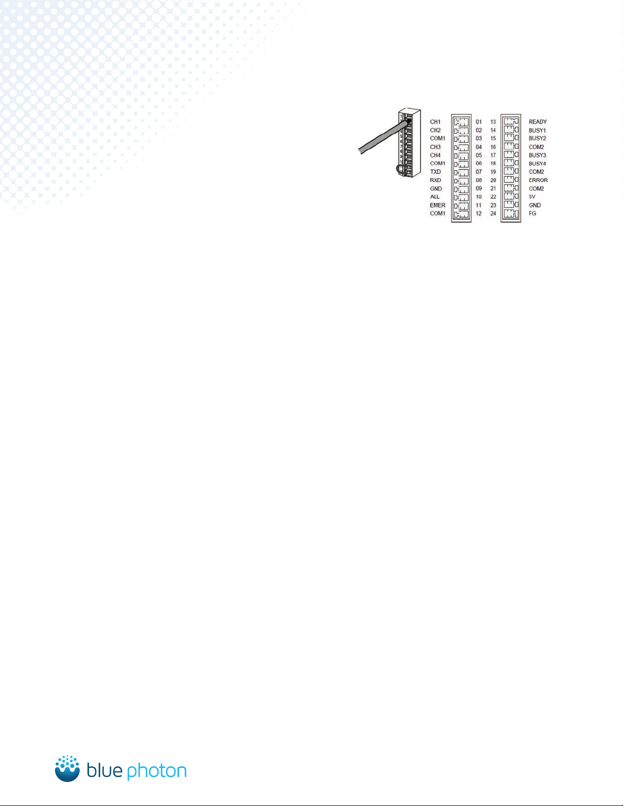
3.1 Signal Ports
Connector ion for external control (12 pin x 2)
• Tightening torque: 0.2N*M ~ 0.3N*M
• When peeling off the coating, be careful to
not damage the wires core.
• Do not twist the wires when connecting them.
• Do not put pull on the wires after connecting.
Pin No. Signal Port Functions
1. CH1 Channel 1 Stop / Run
2. CH2 Channel 2 Stop / Run
3. COM1 Grounded Common Input Terminal
4. CH3 Channel 3 Stop / Run
5. CH4 Channel 4 Stop / Run
6. COM1 Grounded Common Input Terminal
7. TXD RS232 Data Transmission Terminal
8. RXD RS232 Data Receiving Terminal
9. GND RS232 Grounded Terminal
10. ALL All Channels Stop / Run
11. EMER Emergency Stop the Controller
12. COM1 Grounded Common Input Terminal
13. READY Ready for Running Signal Feedback
14. BUSY1 Channel 1 Running Signal Feedback
15. BUSY2 Channel 2 Running Signal Feedback
16. COM2 Grounded Common Output Terminal
17. BUSY3 Channel 3 Running Signal Feedback
18. BUSY4 Channel 4 Running Signal Feedback
19. COM2 Grounded Common Output Terminal
20. ERROR Fault Signal Feedback
21. COM2 Grounded Common Output Terminal
22. 5V DC5V Output, Max. 100mA
23. GND DC5V Grounded Terminal
24. FG Forced Grounding Terminal

Blue Photon Proprietary Information 7®
3.2 External Signal Connections
Output Specications:
• Output Capacity: 10mA.
• Rated Load Voltage: DC 5~24V.
• Maximum Load Current: 10mA (for each output).
• When using the internal 5V power, the maximum load current should be less than 100mA.
• Maximum Voltage Drop: below 0.9V at “ON” status.
3.3 RS232 Ports
DSUB Connector 9 Pin
Pin No. Signal Port Abbreviation
1. Not Connected —
2. Send Data SD
3. Receive Data RD
4. Not Connected —
5. Signal Grounded SG
6. Not Connected —
7. Not Connected —
8. Not Connected —
9. Not Connected —
INPUT
No-voltage input from
open collectors or relays.
Rated Voltage: 5~24VDC
Output Capacity: 100mA (max)
Foot Pedal
5~24VDC
PLC Trigger Signal
OUTPUT
CONTACT INPUT
EXTERNAL POWER SUPPLY
NO CONTACT INPUT
INTERNAL POWER SUPPLY
RS232

www.BluePhotonGrip.com • 855-777-2040
8
®
User Guide
****Control Command****
• Stop / Run One UV Channel: “0x23 + 0x0E + address + 0xff + 0x01”. Data low bit “1” represents UV
channel run, “0” represents UV channel stop. “0x0E” is the command of UV channel Stop / Run.
• PULSE or LOW Mode Setting: “0x23 + 0x0F + address + 0xff + 0x01”. Data low bit “1” represents LOW
mode, “0” represents PULSE mode. “0x0F “ is the command of PULSE or LOW mode setting.
• UV Power Setting: ”0x23 + 0x00~0x0D + address + 0xff + 0xff“. Data low bit represents standard
brightness value, 0-100%. “0x00~0x0D” in turn represents the brightness value of the A/M/ST1~ST12, a
total of 14 brightness values.
• Running Mode Setting: “0x23 + 0x1E + address + 0xff + 0x01”. Data low bit “1” represents A mode, “2”
represents ST mode, “3” represents M mode, “4” represents CLOSE mode. “0x1E “ is the command of
running mode setting.
• ST Mode Step Number Setting: “0x23 + 0x1F + address + 0xff + 0x01” “0x1F“ is the command of step
number setting. The total step number is 12.
• Irradiation Time Setting: ”0x23 + 0x10~0x1C + address + 0xff + 0xff “. High or low data bytes represents
working time, 0-9999, unit 0.1s. “0x10~0x1C” in turn represents the brightness value of the A/ST1~ST12, a
total of 13 brightness values.
The high data bytes represents the high byte of time, the low data bytes represents the time of the low byte,
making up an integer data.
Afterallcommandsarecorrectlyreceived,itwillreturn“0x24”atthebeginningofatotalofvebytesdata.
****Check Command****
”Command + 0x40” represents check command.
• Check Running Status: ”0x23 + (0x0E + 0x40) + address + 0xff + 0x01”> Response: ”0x24 + (0x0E + 0x40)
+ address + 0xff + 0x01”. Data low bit “1”, represents UV channel run, “0”, represents UV channel stop.
• Check PULSE or LOW Mode: “0x23 + (0x0F + 0x40) + address + 0xff + 0x01”. Response: ”0x24 + (0x0F +
0x40) + address + 0xff + 0x01”. Data low bit “1”, represents LOW mode, “ 0”, represents PULSE mode.
• Check UV Power Setting: ”0x23 + (0x00~0x0D + 0x40) + address + 0xff + 0xff”. Response: ”0x24 +
(0x00~0x0D + 0x40) + address + 0xff + 0xff”. Data low bit represents standard brightness value, 0-100%.
”0x00~0x0D” in turn represents the brightness value of the A/M/ST1~ST12, a total of 14 brightness values.
• Check Running Mode: ”0x23 + (0x1E + 0x40) + address + 0xff + 0x01“. Response: ”0x24 + (0x1E + 0x40)
+ address + 0xff + 0x01“. Data low bit “1” represents A mode, “2” represents ST mode, “3” represents M
mode, “4” represents CLOSE mode.
3.4 Serial Communication Protocol
Signal Port RS232
Communication Mode Half Duplex Mode
Synchronous Mode Start and Stop Synchronization Mode
Transmission Cable 3 Core Shield Wire
Transmission Distance ≤15M
Transmission Speed 9600 DPS
Transmission Code ASCII
Transfer Format Data Length: 8 BIT
Check Bit: None
Stop Bit: 1 BIT
(1) Connected to the Controller
Connect a “UV LED” head to the controller,
the controller returns ”:“ (Hex 0x3A) means
the connection is successful.
(2) Instructions Format
0x23 + Command + Address +
Data (High 8 BIT) + Data (Low 8 BIT)
ADDRESS
”00” Represents UV Channel 1
“01” Represents UV Channel 2
“02” Represents UV Channel 3
“03” Represents UV Channel 4

Blue Photon Proprietary Information 9®
• Check Step Number: ”0x23 + ( 0x1F + 0x40) + address + 0xff + 0x01”. Response: ”0x24 + (0x1F + 0x40) +
address + 0xff + 0x01”. Data low bit represents step number. The total step number is 12.
• Check Irradiation Time: ”0x23 + (0x10~0X1C + 0x40)+ address + 0xff + 0xff“. Response: ”0x24 + (0x10~0x1C
+ 0x40) + address + 0xff + 0xff”. Two lowest bytes corresponds to high or low bytes of time. 0-9999, Unit: 0.1s.
0x10~0x1C in turn represents the brightness value of the A/ST1~ST12, a total of 13 time values.
• Check the Total Running Time: ”0x23 + 0x25 + address + 0xff + 0xff “. Response: ”0x24 + 0x25 + address +
0xff + 0xff “. Two lowest bytes corresponding to the cumulative time of the high, low byte, unit: H.
**** Fault Feedback ****
Feedback: ”0x24 + 0x00 + address + 0x0E + 0x20“. Two lowest bytes are corresponding to the error code. ”E20”
represents open circuit fault; ”E30” represents short circuit fault; ”E40” represents overheat fault.
****Save Settings****
Command: “0x23 + 0xEE + 0xAA + 0xff + 0xff” Response: ”0x24 + 0xEE + 0xAA + 0xff + 0xff”
****Setting Examples****
Run UV Channel 1: 0x23 0x00 0x00 0x00 0x01 Stop UV Channel 1: 0x23 0x00 0x00 0x00 0x00
Set UV Channel 1 A Mode and 100% UV Power: 100% 0x23 0x00 0x00 0xFF 0x64
Set UV Channel 1 M Mode and 80% UV Power: 0x23 0x01 0x00 0xFF 0x50
Set UV Channel 1 A Mode and 25.6 S Irradiation Time: 0x23 0x10 0x00 0x01 0x00
Set UV Channel 1 M Mode: 0x23 0x1E 0x00 0xFF 0x03
Set UV Channel 1 A Mode: 0x23 0x1E 0x00 0xFF 0x01
Set UV Channel 1 LOW Mode: 0x23 0x0F 0x00 0xFF 0x01
3.5 Command and Response
• The commands sent to the controller are called “command”.
• The codes returned by the controller are called “response”.
• After the command is sent, it will return a response.
• Send ASCII code.
If there is no response, there might be a problem with transmission format and command not being received.
Pleaseconrmthecommunicationspeed,datalength,odd-evencheck,andsoonarecorrect.
The controller indicates that the command is not properly handled when the response doesn’t include “$”, but
includes “!”, please refer to the default settings.
System Operating Instructions
4.1 Operating Parameters
No.Parameters Description
1. A Automatic Irradiation Mode
2. M Manual Irradiation Mode
3. CLOSE Close the UV Channel
4. 16ST Step Irradiation: 1~16 Step Number
5. PS Cycle the Step Irradiation: 1~99 Times
6. 100% UV Power: 0~100% Adjustable
7. 999.9 S Irradiation Time: 0~999.9 S

www.BluePhotonGrip.com • 855-777-2040
10
®
User Guide
4.2 Operating Parameters Setup
1. Turn the controller power switch on.
2. Turn the key switch on, located on front of control panel.
3. Press the “Run / Stop” button.
See below for example:
4. Press the “Set” button to enter into parameters setup mode.
See below for example:
5. Press “ ” and “ ”buttontomovethecursortotheitemneedingmodications.
6. Press “ ” and “ ” button to set the parameters.
7. Forthe16STmodesetting,press“Set”buttonafterthestepnumberisconrmed.Repeat5.and6.for
UV power and irradiation time setup. If the step number is over 4, press “Ent” button to display the next
page.Repeatituntilallissetupandnished.
8. Press the “Ent” button to save parameters.
9. If you don’t need to change the parameters, press “Esc” button.
10.Turn off the key switch and remove the key. The setup can only be done when the key switch is turned on.
11.Control the controller via UV channel buttons, foot pedal, PLC, and other external signal. The controller
will run accordingly to the settings.
4.3 System Parameters
No.Parameters Description
1. START START PULSE: Represents trigger signal.
START LOW: Represents continuous signal.
2. 000000H00M00S Register the total irradiation time of the UV channel.
3. LINK LINK ON: The UV channels can be controlled by an external signal.
LINK OFF: The UV channels can be controlled by the independent signal.
4. LOCK
LOCK ON: Under the automatic irradiation mode, the controller will not stop at the
set time.
LOCK OFF: Stop the controller at any time by control signal.
5. BUZZ BUZZ ON: Open the buzzer.
BUZZ OFF: Close the buzzer.
6. COPY COPYON:Copytheoperatorparametersoftherst“COPYON”settingchannel.
COPY OFF: Keeps the UV channels at default setting.
CH1 80% A STOP
CH2 80% M STOP
CH3 CLOSE STOP
CH4 16ST STOP
CH1 80% A 010.0 S
CH2 80% M
CH3 CLOSE
CH4 16ST
ST01 100% 000.0 S
ST02 100% 000.0 S
ST03 100% 000.0 S
ST04 100% 000.0 S

Blue Photon Proprietary Information 11 ®
4.4 System Parameters Setup
1. Turn the controller power switch on.
2. Turn the key switch on, located on front of control panel.
3. Press the “Run / Stop” button.
4. Press the “Set” button for over three seconds to enter into parameters setup mode.
See below for example:
5. Press “ ” and “ ”buttontomovethecursortotheitemneedingmodications.
6. Press “ ” and “ ” button to set the parameters.
7. Press the “Set” button for over three seconds to save parameters.
8. If you don’t need to change the parameters, press “Esc” button.
9. Turn off the key switch and remove the key. The setup can only be done when the key switch is turned on.
4.5 Blue Photon Factory Settings
Setup:
A Mode: UV Power 100%
Irradiation time 060.0s
1. Turn the controller power switch on.
2. Turn the key switch on, located on front of control panel.
3. Press the “Run / Stop” button.
4. Press the “Set” button to enter into parameters setup mode.
5. Press “ ” and “ ” button to move cursor “_” to the irradiation mode.
6. Press “ ” and “ ” button to change it to A mode.
7. Press “ ” and “ ” button to move cursor “_” to the UV power.
8. Press “ ” and “ ” button to change it to 100%.
9. Press “ ” and “ ” button to move cursor “_” to the irradiation time.
10.Press “ ” and “ ” button to change it to 060.0s.
11.Press the “Ent” button to save parameters.
CH1 START PULSE
CH2 START PULSE
CH3 START PULSE
CH4 START PULSE
CH1 100% A 060.0 S
CH2 100% A 060.0 S
CH3 100% A 060.0 S
CH4 100% A 060.0 S
Left: CH1~CH4 is the UV Channel Number
Middle: UV Power / Irradiation Mode
Right: Irradiation Time
www.BluePhotonGrip.com • 855-777-2040
1002 Industrial Park Dr., Shelby, MI 49455
®
Maintenance
5.1 Safety Cautions
• Only trained personal should attempt to repair.
• Turn off power supply before attempting to begin maintenance.
• Pull out the power plug before disassembling the equipment to avoid electric shock.
• Wear UV light blocking goggles, glasses or shield, leather gloves or similar light blocking gloves, and long
sleeves during operations.
5.2 Maintenance and Cleaning
• Measure the UV intensity or UV energy with UV-A meter periodically. If it is not enough for curing, please
replace it with a new UV LED head. The calibration period is related with the running frequency. Minimum
UV output is 350 mW.
• During use, the UV LED head can be polluted by the volatile of UV adhesive and the environmental dust. It
is necessary to clean the optical lens and tube to ensure the UV intensity and heat dissipation. Please use
lens tissue, non-dust cloth and alcohol for cleaning. Please turn off the power and make sure it is completely
cool before cleaning.
©2022 Blue Photon Technology & Workholding Systems LLC. All Rights Reserved. Blue Photon has made every effort to ensure the accuracy
of the product information in this document; however, we are not responsible for typographical discrepancies. Actual products may vary from
those shown in photos. Refer to our website for current product and safety information. Blue Photon BlueCure Mini 4 V1.0 10644 11.09.22
This manual suits for next models
1
Table of contents


