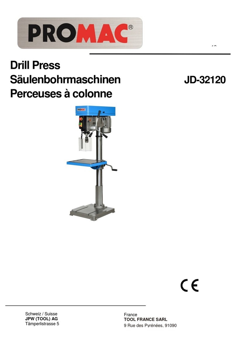
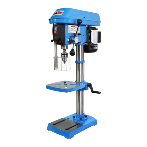
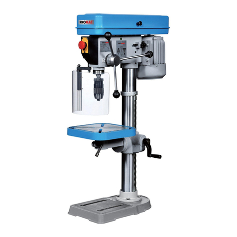
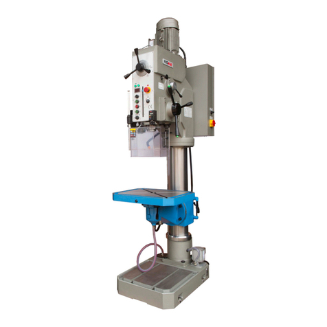
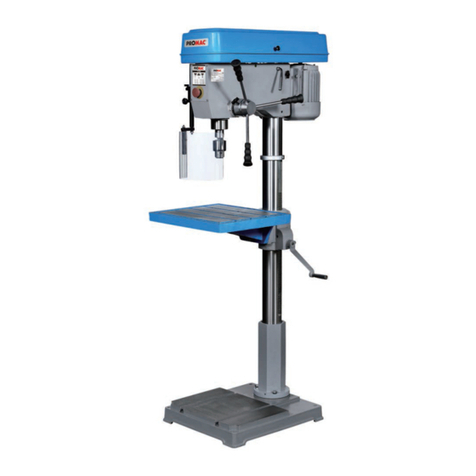
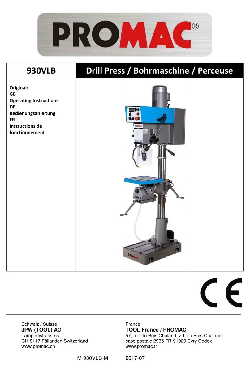
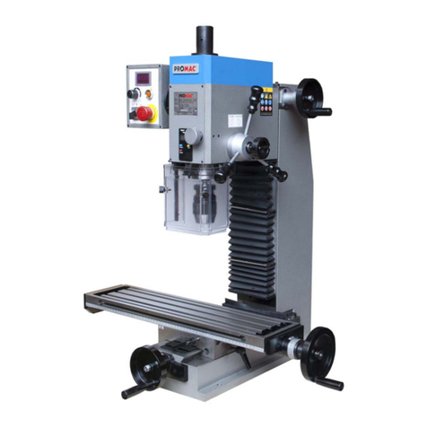
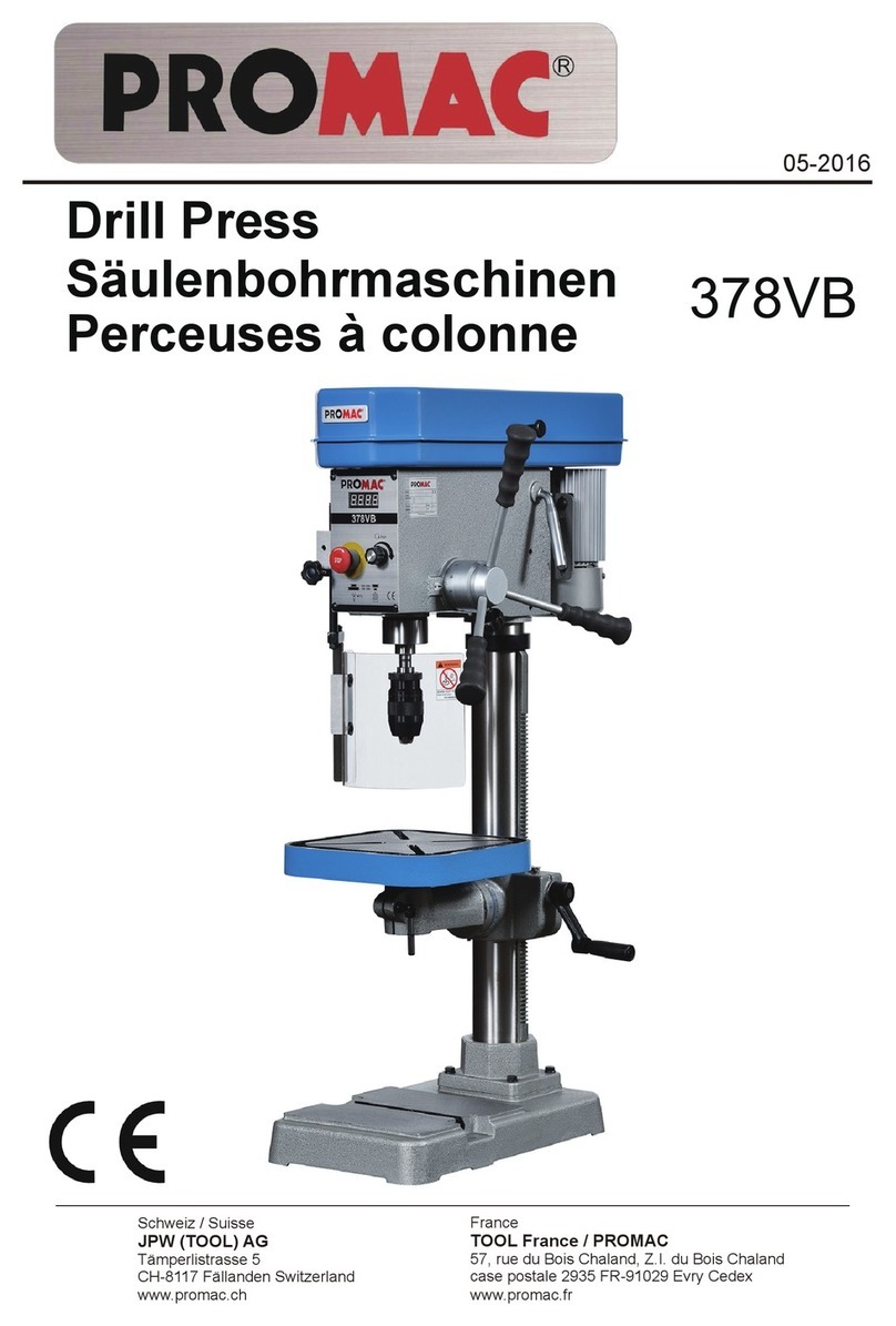
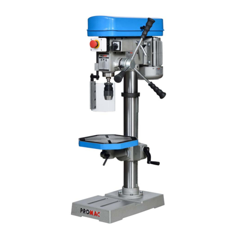
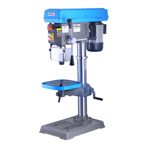
Promac 378VLB User manual

378VLB
Schweiz / Suisse
JPW (TOOL) AG
Tämperlistrasse 5
CH-8117 Fällanden Switzerland
www.promac.ch
France
TOOL France / PROMAC
57, rue du Bois Chaland, Z.I. du Bois Chaland
case postale 2935 FR-91029 Evry Cedex
www.promac.fr
06-2016
Drill Press
Säulenbohrmaschinen
Perceuses à colonne

CE-Conformity Declaration
CE-Konformitätserklärung
Déclaration de Conformité CE
Product / Produkt / Produit:
Drill Press
Säulenbohrmaschine
Perceuse à colonne
ϯϳϴs>
Brand / Marke / Marque:
PROMAC
Manufacturer / Hersteller / Fabricant:
JPW (Tool) AG, Tämperlistrasse 5, CH-8117 Fällanden
Schweiz / Suisse / Switzerland
We hereby declare that this product complies with the regulations
Wir erklären hiermit, dass dieses Produkt der folgenden Richtlinie entspricht
Par la présente, nous déclarons que ce produit correspond aux directives suivantes
2006/42/EC
Machinery Directive
Maschinenrichtlinie
Directive Machines
2014/30/EU
electromagnetic compatibility
elektromagnetische Verträglichkeit
compatibilité électromagnétique
designed in consideration of the standards
und entspechend folgender zusätzlicher Normen entwickelt wurde
et été développé dans le respect des normes complémentaires suivantes
EN ISO 12100:2010
EN 12717:2001+A1:2009
EN 60204-1:2006+A1:2009
EN 61000-6-2:2005
EN 61000-6-4:2007+A1:2011
Responsible for the Documentation / Dokumentations-Verantwortung / Résponsabilité de Documentation:
Hansjörg Meier
Head Product-Mgmt. / Leiter Produkt-Mgmt. / Resp. Gestion des Produits
JPW (Tool) AG
2016-0ϲ-2ϯAlain Schmid, General Manager
JPW (Tool) AG, Tämperlistrasse 5, CH-8117 Fällanden
Schweiz / Suisse / Switzerland

NOTE:
It is advisable for user to read this Instrucon Manual in order to avoid accident.
If the operaon method used in this drilling machine us the same as the method used in ordinary
machine, possible hazard may occur during the process. Therefore, it isimperave that user should pay
extra auon and make sure that his operang method is correct. Slight negligence to any of the safety
measures will certainly cause accident to the user.
The manufacturer designed this machine especially focusing on its scheduled using scope. Therefore, it
is advisable that the user should pay aenon not to exceed the said using scope. Also, do not make any
modificaon to the spare parts and structure of the machine.
If you have any queson regarding and operang method of this machine and Cannot find the soluon
in the Instrucon Manual, please contact your vendor directly.
Correct Operation Instruction of This Machine
1. For your own safety, do not start the said machine before reading the Instrucon Manual carefully. One
of the necessary safety measures is to understand its operaon principle and operaon method first.
2. Do not alter any of the protecve pieces in order to maintain its completeness
3. Plug the fan plug for power supply into the socket with earth wire. If your socket dose not have an
earth wire, then connect the earth terminal of this machine
4. Before starng this machine, it is imperave to take away all wrenches and latch handle not connected
to the machine. Also, your should make it a habit to check the surrounding of the said machine every
me before suing, to see there is any small spare part around that may cause running fault breakdown).
5. Before installing the machine, clean your working ground on order to prevent any accident occurring.
6. Do not use this machine in a highly dangerous place. Also, do not install the machine in a humid or
water leaking place. During the process of work, the user should make sure to keep its working ground
clean anyme.
7. Do not let any unauthorized or ignorant person or children near the said machine, and should be sure
to keep a proper distance from the machine anyme.
8. Put a safety lock on the door of your working ground in order to prevent children from starng the
machine.
9. Avoid overloading the machine. Also, for your own safety, be sure to abide to its using scopes.
10. Do not use the machine outside its using scope.
EN – ENGLISH
3

1. Wear proper clothes while working. Do not wear any clothes that can easily be ripped by the machine
while operating, such as clothes that flutter, ordinary gloves scarf, ring, and small chain. You should
also wear anti-skid shoes and hat (cap) that can fully hold in long hairs.
2. When operating this machine, you should wear a goggle and dust-proof mask anytime. Besides, make
sure to abide to the related safety measures specified by the government’s Bureau of Works.
3. Use a hand vice or other fixing device to fix all the spare parts for processing. Do not use your hands to
fix them in order to avoid serious accident and unable to operate the said machine.
4. Stand firmly in front of this machine while working (both feet’s position, body equilibrium, etc.)
5. Keep the machine and its pointed edges clean at all time in order to get the best working efficiency.
Also, should follow the instructions in the Instruction Manual carefully in changing the tools, coating
grease, and cleaning.
6. Before cleaning this machine or changing the tools (such as saw blade, drill),pull off the power plug first
to avoid electrocution.
7. Use the tools suggested by the manufacturer of this machine while working and abide to the related
instruction in the Instruction Manual, because using spare parts not related to this machine is an
unsafe behavior.
8. Avoid touching the machine unintentionally. Also, before plugging in the plug into the socket, check if
switch button is as 【OFF】position or not.
9. Do not stand on the machine in order to avoid slipping down carelessly or hitting the blade and cause
injury.
10. Remember to check abnormal part in the running process of the machine carefully.
It is advisable that you should change the said part or protective piece before continuing the work.
11. Do not leave the working ground while the machine is running. It is necessary for your to leave, turn
off the power and wait for the machine to stop completely before leaving.
12. Do not use this machine if you had taken any alcohol (liquor or wine), medicine, or drugs.
4

1 PARTSA
Unpack carton, check your machine to see parts listed below:
A. Main Parts:
1. Head assembly 1 pc
2. Column with flange 1 pc
3. Arm of table and bracket 1 set
4. Table 1 pc
5. Base 1 pc
B. Accessories
1. Screw & washer 4 sets
2. Clamp bolt ( Table arm ) 1 pc
3. Clamp bolt (Table bracket) 1 pc
4
5. Bow-shaped handle
. Knob (Pulley cover) 1 pc
6. Allen key ( 3mm, 5mm ) 2 pcs
7. Height adjus ng handle 1 pc
8. Feeding handle & knob 3 sets
9. Chuck guard 1 pc
10. Arbor & wedge 2 pcs
11. Chuck 1 pc
Note: If you find and parts missing or damaged, contact thr dealer for exchange or replacement
1
2
3
4
5
1 pc
5

II. ASSEMBLY
1. Assembly the Column
* Place column assembly on base and align holes in column support
with holes in base.
* Secure the column with four or three bolts and washers provided.
Fig. 1
2. Install table bracket
2-1 Take off collar and rack
2-2 Install table bracket togeter with rack. Fig. 2.
Fig. 2
3. Install bracket handle and clamp bolt. Fig. 4-5
Fig.3
3. Griff der Halterung und Befestigungsschraube installieren
(Abb. 4-5)
Fix handle with attached set screw.
Fig.4
Install clamp bolt to fix table bracket.
Fig.5
6

4. Install table and clamp with bolt. Fig. 6
Fig.6
5. Aach the Head Assembly
* Carefulley put the head assembly over column and slide it
onto column into posion. Align head frame with table
and base.
* Fix set screws in right side of head to lock head into
posion then ghten with allen wrench. Fig. 7
Fig.7
6. Install the Feeding Handles.
* Screw knob on each feeding handle, install them
into hub of pinion sha. Fig. 8
Fig.8
7. Aach the Arbor and Chuck
7-1 Insert abor into spindle first. Pull feeding handle
down to press abor inward. Fig.9
7-2 Open chuck jaws completely by turning aached
chuck key counter clockwise to the end. Put a
piece of scrap wood on the table to protect chuck
nose.
7-3 Install chuck to the arbor ghtly. Fig.10
Fig.9
8. Install knob and screw of upper pulley cover. Fig.11
Fig.11 Fig .10
7

III ADJUSTMENT
1. Table Adjustment
A. Height Adjustment
To adjust up or down, loosen the clamp bolt then adjust the table
to your desired position by swing the table bracket handle.
Fig. 12
Fig. 12
B. Tilting Adjustment:
Loosen the table bevel lock bolt with adjustable wrench.
Tilt table to desired angle and retighten the bolt. Fig. 13
Fig. 13
C. Swing 360 °
Loosen clamp bolt then swing table to appropriate
position and retighten clamp bolt. Fig. 14
Fig.14
2. Feed Depth Adjustment
2-1 Depth control scale sleeve type Loose the clamp bolt
and move to the desired depth then retighten the clamp olt.
Fig. 15-1, 15-2
Fig.15-2 Fig.15-1
Table bracket h
andle
Lock nut
Clamp bolt

3. Speed Adjustment
3-1 1. Open the pulley case and 1 the belt tension lock
handle.
2. Choose speed for drilling operaon and move belt to
correct posion for desired speed.
3. Push motor backward unitl moderate belt tension is
acquired. Then reghten the lock handle again.
Fig 16
Fig.16
The proper drill speed fo r a given drill bit size is as on following table:
9

BEDIENPANEL
EMERGENCY SWITCH
O
I
( SWITCH ) SPEED REGUAL TOR
Operation
1. This machine is equipped with a 2 HP 180V DC - Adjusting belt tension
collector motor. The voltage is 230V and this is Use a spanner to tightenor loosen the bolt
stepped up to 180V DC in the machine. (itemno. 43 ) to achieve the correct tension.
2. The motor is fitted exceeds 15A a warning single - Belt replacement
willbe heard and the machine should be stopped Use a spanner to loosen the bolt (itemno.43) and
immediately. Stop work and wait a few seconds release the belt tension. Replace the belt.
untilthe signalstops. It is then safe to resume work. Set the correct belt tensionbytighteningthe bolt.
Ifyou continue work instead of stopping and waiting, - After adjusting the belt tension or replaceing the
thee machine willstop automatically after 2 seconds. belt, tightenthe 4 nuts onthe motor.
In this case you willneed to start the machine again. - Close the cover over the belt pulleys and fastenit
3. Spindle speed is from200 to 2100 rpm. The re- with the original screws.
gulator for adjusting and setting the speed is easily 5. Motor service
accessible on the front panel. - The motor is a 2 HP 180DC model.
4. Replacing the belt or adjusting the belt tension. - The motor has 2 carnob brushes with a lifespan of
- Open the cover above the belt pulleys. Use a 1,000 working hours.
screwdriver to remove the screw onthe front of Always replace both at the same time when the motor
the cover and open the cover as much as possible. output is low.
- The motor is fixed in place with 2 nuts
(itemno. 37). Lossen these.
10

Special Safety Rules For Drill Press:
1. Caution : This drill press is intended for use only with drill bits. This use of other accessories may be
hazardous.
2. Correct drilling speeds : Factors which determine the best speed to use in any drill press operation
are :Kind of material being worked, size of hold, type of drill or other cutter, and quality of cut desired.
The smaller the drill, the greater the required RPM. In soft materials, the speed should be higher than
for hard metals.
3. Drilling in metal: Use clamps to hold the work when frilling in metal. The work should never be held in
there bare hand, the flutes of the drill may seize the work at any time, especially when breaking
through the stock. If the piece is whirled out of the operator's hand, he may be injured, in any case, the
drill will be broken when the work strikes the column.
4. The work must be clamped firmly while drilling : Any tilting, twisting, or shifting results not only in a
rough hold, but also increases drill breakage. For flat work, lay the piece on a wooden base and clamp
it firmly down against the table to prevent it from turning. If the piece is of irregular shape and cannot
be laid flat in the table, it should be securely blocked and clamped.
5. The chuck shall be securely fastened to the spindle and so that it can’t separate from spindle.
6. Remove Key from chuck after adjustment.
7. The tool is to be disconnected from the power supply while the motor is being mounted, connected or
reconnected.
8. Secure the tool to the supporting structure if, during normal operation, there is any tendency for the
tool to tip over, slide, or walk on the supporting surface.
9. The set screws of head frame should be screwed tightly before suing this machine.
10. Connect to a supply circuit protected by a circuit breaker or time delay fuse.
11. Fasten base to floor or worktable before using the drill press.
VII. Important Notice For CE
Handling of Machine
1. The total weight of this machine must be ensured before handling.
2. It is better to handle this machine with the help of lifting tools.
Environment Requirements for Installation
1. Be sure to provide sufficient light for operation according to the codes or regulations published for
local area. If you do not get the information about lighting, a light intensity of 300 Lux is the least
value to be supplied.
2. The place where machine install must be flat and big enough for the operation.
Noise Level
1. The noise level of this machine is about 75 db(A)during operation.
2. While taking provisions for the risk of noise, the noise level of working environment should be
taken into consideration also.
11

VII Electric
ELECTRICAL CONNECTION/DISCONNECTION & OPERATION
For three phase :
1. Electrical connection:
1. A cable with four wires is equipped to connect your machine into the 3 phase power supply.
Please connect your machine into the power supply with hand-operated disconnecting device, which
is in compliance with subclause 5.3 of EN 60204-1, such as on fuse breaker or plug/socket combination.
2. For the protection of control device, we recommend the operation to supply a fuse with 6 A current
rating of fuse, and the total length between fuse and connection terminal shall not exceed 1.5m.
3. The exact power source voltage, frequency, and number of phase shall be checked according to the
installation diagram and circuit diagram.
4. The correct direction of drilling press should be checked after connecting.
2. Electrical disconnection:
1. The disconnection is carried out by hand-operated disconnection device.
2. Be sure to disconnect this machining from power source, when you want to stop the job, Maintenance,
and adjustment.
3. Grounding
The grounding of the drilling press is carried out by connecting the Yellow/Green terminal of supply
cable to the grounding terminal of power source. Be sure to ground your machine before connecting
machine to power source in any situation.
WARNING !
Do not disconnect grounding terminal before disconnecting power source.
For single phase :
1. The connect, disconnection, and grounding is carried out through the plug, equipped on the drilling
press. For the safety reason, Do not change this plug into any the other type in any situation.
2. For the protection of control device, we recommend the operated to supply a fuse with 6 A current
rating of fuse, and the total length between buse and connection terminal shall not exceed 1.5m.
3. The exact power source voltage, frequency, and number of phase shall be checked according to the
installation diagram and circuit diagram.
Operation:
1. "START" : Push the button marked with " I ".
2. "STOP": Push the button marked with " O".
3. "Interlock Switch": Limit switch in the pulley cover.
WARNING !
Do not stop machine with interlock switch in normal operation.

HINWEIS:
Bie lesen Siedie vorliegende Bedienungsanleitung sorgfälg durch und beachten allehierin enthaltenen
Sicherheits- und Vorsichtsmaßnahmen, um Unfällezu vermeiden.
Bei Anwendung vonBetriebsmethoden, wiesieauf anderen Maschinen üblich sind, auf dieser
Säulenbohrmaschine kann es während des Bearbeitungsprozesses zu Unfällen, Kollisionen usw. kommen.
Daher muss der Bediener stets sorgfälg darauf achten, dass Betriebs- und Bearbeitungsmethoden dem
besmmungsmäßigen Gebrauch gemäß den Vorschrien indiesem Handbuch entsprechen. Bei auch nur
geringfügiger Abweichung vonden vorgeschriebenen Sicherheitsmaßnahmen kann es zu
schwerwiegenden Unfällen mit Personen- und Sachschäden inFolge kommen.
Der Hersteller gewährleistet Sicherheit und zugesicherte Eigenschaen dieser Maschine nur unter
Einhaltung ihres besmmungsgemäßen Gebrauchs.Es obliegt daher dem Betreiber/Bediener der
Maschine, alle Vorschrien und Maschinenspezifikaonen einzuhalten und zu beachten. Zudem sind
jegliche Änderungen an Maschinenauau und Zubehör untersagt.
Bei Fragen bezüglich Betriebsmethoden dieser Maschine wenden Siesich bie direktan Ihren
zuständigen Händler, sollten SieAntworten auf die Fragen nicht indieser Bedienungsanleitung finden.
Anweisungen für den korrekten Maschinenbetrieb
1.Lesen SieimSinne Ihrer eigenen Sicherheit die Bedienungsanleitung vor Start des Maschinenbetriebs
sorgfälg durch. Einumfassendes Verständnis des Arbeitsprinzips und der Betriebsmethoden der
Maschine istwesentlicher Bestandteil der Sicherheitsmaßnahmen.
2.AlleSchutzvorrichtungen der Maschine dürfen weder manipuliert noch inirgendeiner Weise geändert
werden, um ihre Integrität nicht zu beeinträchgen.
3.Schließen Sieden Netzstecker des Lüers an eine geerdete Stromquelle an. IstIhre Netzsteckdose
nicht mit Schutzleiter versehen, muss der Anschluss an die Masseklemme dieser Maschine erfolgen.
4.Vor Start der Maschine müssen alle nicht für den Maschinenbetrieb erforderlichen Werkzeuge
(Schraubenschlüssel,Griffe usw.) enernt werden. Überprüfen Siedie Maschinenumgebung zudem
vor dem Start rounemäßig auf zurückgebliebene kleine Ersatz- und andere Teile, die zu Kollisionen
und Ausfall der Maschine führen können.
5.Vor Installaon der Maschine muss die Arbeitsumgebung gründlich gereinigt werden, um Unfällemit
Personen- und Sachschäden zu vermeiden.
6.Der Einsatz der Maschine ingefährlicher Umgebung - gleich aus welchem Grund - iststriktuntersagt.
Der Aufstellortder Maschine muss frei vonLufeuchte und eindringendem Wasser sein.Auch
während der Bearbeitung muss die Arbeitsumgebung stets sauber gehalten werden.
7.Gestaen Sieden Aufenthalt unbefugter Personen nicht inMaschinennähe und halten Sieselbststets
ausreichenden Abstand zur Maschine und ihren beweglichen Teilen.
8.Versehen Sieden Zugang zum Arbeitsbereich mit einem Sicherheitsschloss, um unbefugten Personen
den Zutriund potenziellen Start der Maschine zu verwehren.
9.Jegliche Überschreitung der max.Spezifikaonen der Maschine istunzulässig. Die Einhaltung aller
Sicherheitvorschrien, Grenzwerte usw. liegt inIhrem eigenen Sicherheitsinteresse.
10.Die Maschine darf nur für den besmmungsgemäßen Gebrauch verwendet werden.
DE – DEUTSCH
13

1.WährendallerArbeitenistgeeignetepersönlicheSchutzausrüstungzutragen.DasTragenvonloser
Kleidung,KettenundRingen(SchmuckimAllgemeinen)sowieandererinbeweglichen
MaschinenteilenverfänglicherGegenständeistuntersagt.DasTragenvonSicherheitsschuhenund
Kappen/Schutzhelmenistebenfallsvorgeschrieben;offenelangeHaaresindstriktuntersagt.
2.WährenddesMaschinenbetriebsistdasTragenvonSchutzbrilleundstaubdichterMaske
vorgeschrieben.Zudemsindallelokalen/regionalenarbeitsschutzrechtlichenSicherheitsmaßnahmen
einzuhalten.
3.VerwendenSieeinenmanuellenSpannstockoderandereSpannvorrichtungfürdasAufspannenaller
ZubehörteilefürdieBearbeitung.
BeiAufspannenmitbloßerHandkannesanderfallszuschwerwiegendenVerletzungenkommen.
4.SorgenSiebeiArbeitenanderMaschinefürfestenStand(beideFüßefestaufdemBoden,Körperim
Gleichgewichtusw.).
5.HaltenSieMaschineundspitzeKantenusw.stetssauber,umbestmöglicheArbeitseffizienzzuerzielen.
BefolgenSieaußerdemgenaualleAnweisungenbezüglichWerkzeugwechsel,Schmierung(Fett,Öl)
undReinigunginderBedienungsanleitung.
6.VorReinigendieserMaschineoderAuswechselnvonWerkzeugen(wiez.B.Sägeblatt,Bohrerusw.)
musszuerstderNetzsteckergezogenunddieMaschinevomNetzgetrenntwerden,umdieGefahrvon
Stromschlägenzuvermeiden.
7.VerwendenSieausschließlichdievomMaschinenherstellervorgeschriebenenWerkzeugefürArbeiten
anderMaschineundbeachtenalleinderBedienungsanleitungenthaltenenSicherheits‐undanderen
Vorschriften,daz.B.dieVerwendungandereralsdervorgeschriebenenZubehör‐undErsatzteileals
unsicheresVerhaltengiltundzuAusschlussderGarantiesowieUnfällenführenkann.
8.JedeunbeabsichtigteBerührungderMaschineistverboten.VorAnschlussandasStromnetzmuss
sichergestelltwerden,dassderNetzschalteranderMaschineausgeschaltetist=【OFF】.
9.DasBesteigenderMaschineistuntersagt,daesandernfallsdurchAusrutschenunddurchKontaktmit
demSägeblattusw.zuschwerenVerletzungenkommenkann.
10.WährendderBearbeitungmussdieMaschinekontinuierlichaufUnregelmäßigkeiten,unrundlaufende
Teileusw.überprüftwerden.
AnormaleTeilebzw.defekteTeilemitSchutzfunktionmüssenvorFortsetzungdesBetriebs
ausgewechseltwerden.
11.VerlassenSieniedenArbeitsbereichbeilaufenderMaschine.VordemVerlassenschaltenSiedie
Stromversorgungausundwarten,bisdieMaschinevollständigabgestoppthat.
12.DerBetriebderMaschineunterAlkoholund/oderDrogen,Medikamentenusw.istbeiStrafeuntersagt.
14

I AUSPACKEN UND ÜBERPRÜFEN AUF VOLLSTÄNDIGKEIT
Packen Sie Ihre Maschine aus und überprüfen sie anhand
der folgenden Teileliste auf Vollständigkeit:
A.
1. 1 Stck.
2. Säule mit Flansch 1 Stck.
3. und -halterung 1 Satz
4. 1 Stck.
5. Standfuß 1 Stck.
B. Zubehör
1. Schraube & Unterlegscheibe 4 Sätze
2. ( ) 1 Stck.
3. ( ) 1 Stck.
4
5. Bügelgriff
. Knopf (Scheibenabdeckung) 1 Stck.
6. Innensechskantschlüssel ( 3mm, 5mm ) 2 Stck.
7. Kurbel für Höhenverstellung 1 Stck.
8. Verstellhebel & -knopf für Maschinenzustellung 3 Sätze
9. Spritzschutzabdeckung 1 Stck.
10. Dorn & Keil 2 Stck.
11. 1 Stck.
Hinweis: Bei fehlenden oder defekten Teilen ren Sie bi e umgehend Ihren Händler bezüglich
Neulieferung/Austausch.
1
2
3
4
5
1 Stck.
15

II.MONTAGE
1.Säulemontieren
*DieSäuleaufdemStandfußplatzierenunddie
BohrungenimSäulenfußmitdenBohrungenim
Standfußausrichten.
*DieSäulemitdenvieroderdreimitgelieferten
SchraubenundUnterlegscheibenaufdemFuß
befestigen.
Abb.1
2.HalterungdesBohrtischesanbringen
2‐1BundundGestellentfernen.
2‐2TischhalterungzusammenmitGestellinstallieren.Abb.2.
Abb.2
2‐3Bundmontierenundfestanziehen.Abb.3
Abb.3
3.GriffderHalterungundBefestigungsschraubeinstallieren
(Abb.4‐5)
GriffmitzugehörigerStellschraubesichern.
Abb.4
BefestigungsschraubezumFixierenderTischhalterungeinsetzen.
Abb.5
16

4. Bohrsch installieren und mit Schraubesichern ( Abb. 6)
Abb.6
5. Kopaugruppe moneren
* Kopaugruppe präzise auf die Säule setzen und entlang
der Säule nach unten in Posionschieben. Rahmen der
Kopaugruppe mit Bohrsch und Standfuß ausrichten.
* Kopf mit Stellschrauben rechts am Kopf fixieren, dann
Schrauben mit Innensechskantschlüssel anziehen. Abb. 7
Abb.7
6. Griffe für dieMaschinenzustellung installieren
* Knopf auf jeden Griff schrauben und Griffe in die Nabe an
der Ritzelwelle einsetzen. Abb. 8
Abb.8
7. Dorn und Bohrfuer moneren
7-1 Zuerst den Dorn in die Spindel einsetzen. Verstellgriff
nach unten ziehen, um den Dorn nach innenzu
drücken. Abb.9
7-2 Bohrfuerbacken durch Drehen des monerten
Fuerschlüssels bis zum Anschlag in
Gegenuhrzeigerrichtung ganz öffnen. EinStück Holz
zum Schutz des Bohrfuerkopfes auf dem Tisch
platzieren.
7-3 Spannfuer sicher auf dem Dorn moneren. Abb.10
Abb.9
8. Knopf und Schraube der oberen Riemenscheibenabdeckung installieren (Abb.11)
Abb.11 Abb.10
17

III EINSTELLUNG
1. Einstellung des Bohrsches
A. Höhenverstellung des Bohrsches
Für die Höhenverstellung des Tisches nach oben und
unten wird die Klemmschraube gelöst und der Tisch
dann durch Drehen der Kurbel an der Tischhalterung in
die gewünschte Posion gebracht. Abb. 12
Abb. 12
B. Verstellung der Tischneigung:
Sicherungsschraube für die Neigungsverstellung des
Bohrsches mit verstellbarem Schraubenschlüssel lösen.
Tisch in die gewünschte Posion neigen und Schraube
wieder anziehen. Abb. 13
Abb. 13
C. 360°-Schwenk um die Tischachse
Klemmschraube lösen und Bohrsch in die erforderliche
Posion schwenken, dann Klemmschraube wieder
anziehen. Abb. 14
Abb.14
2. Einstellung der Zustellefe
2-1 Skala - Tiefeneinstellung (mit Skalenhülse)
Klemmschraube lösen, auf die gewünschte Tiefe
einstellen und Klemmschraube wieder anziehen.
Abb. 15-1, 15-2
Abb.15-2 Abb.15-1
Kurbel zur Höhenverstellung
des Tisches
Sicherungsmutter
Klemmschraube
18

3. Einstellung der Drehzahl
3-1 1. Gehäuseabdeckung der Riemenscheibe öffnen
und Arreerhebel für die Einstellung der
Riemenspannung lösen.
2. Drehzahl für Bohrbetrieb wählen und
Riemenposion auf die gewählte Drehzahl
einstellen.
3. Motor so weit nach hinten schieben, dass eine
mäßige Riemenspannung erreicht ist.
Anschließend wird der Arreerhebel wieder
angezogen. Abb.16
Abb.16
Die korrekte Bohrdrehzahl für die verschiedenen Bohrergrößen finden Sie in der nachfolgenden Tabelle:
19

BEDIENPANEL
Betrieb
1. Diese Maschine ist mit einem2 PS 180V DC
Kollektormotor ausgerüstet. Die Spannung
beträgt 230V und wird in der Maschine in 180V
DC umgewandelt.
2. Bei Überschreiten von 15 A bei installiertem
Motorwird ein Warnton ausgegeben und die
Maschine muss sofort gestoppt werden. In
diesemFall die Bearbeitung sofort beenden und
warten, bis dasSignal nicht mehr ausgegeben
wird. Danach kann die Arbeit sicher fortgesetzt
werden.
Wird die Bearbeitung bei Ausgabe des
Warnsignals nichtgestoppt, erfolgt automatisch
ein Maschinenhalt nach 2 Sekunden.
Danach ist ein Maschinenneustart erforderlich.
3. Die Spindeldrehzahl liegt zwischen 200 und
2100 U/min. Der Drehzahlregler ist über das
vordere Bedienpaneleinfach zugänglich.
4. Auswechseln des Riemens und Einstellung der
Riemenspannung
- Die Abdeckung über den Riemenscheiben
öffnen. Die Schraube an der Frontabdeckung
mit einemSchraubendreherentfernen und die
Abdeckung bis zumAnschlag öffnen.
- Der Motor ist in seiner Position mit 2 Muttern
gesichert (Teil Nr. 37). Die Muttern lösen.
- Einstellung der Riemenspannung
Die Schraube (Teile Nr. 43) mit einem
Schraubenschlüssel anziehen oder lösen, bis
die korrekte Spannung erreicht ist.
- Auswechseln des Riemens
Die Schraube (Teil Nr. 43) mit einem
Schraubenschlüssel lösen, um den Riemen zu
entspannen. Den Riemen auswechseln.
Die korrekte Riemenspannung durch Anziehen
der Schraube einstellen.
- Nach Einstellung der Riemenspannung oder
Auswechseln des Riemens müssen die vier
Muttern am Motor wieder angezogen werden.
- Die Abdeckung über den Riemenscheiben
wieder schließen und mit den vorgesehenen
Schrauben sichern.
5. Motorwartung
- Der Motor ist ein 2 PS 180DC Modell.
- Der Motor verfügt über 2 Kohlebürsten mit
einer Standzeit von 1000 Betriebsstunden.
Bei nachlassender Motorleistung müssen
immer beide Bürsten ausgewechselt werden.
NOT-AUS- SCHALTER
AUS
EIN
( DRUCKTASTER )
DREHZAHLREGLER
20
Table of contents
Languages:
Other Promac Power Tools manuals

Promac
Promac BX-840VADT User manual

Promac
Promac JDT-5030 User manual

Promac
Promac 213A User manual

Promac
Promac 387AB User manual

Promac
Promac PBM-1839V User manual

Promac
Promac 212VLL User manual

Promac
Promac 930VLB User manual

Promac
Promac 212 User manual

Promac
Promac 214AB-M User manual

Promac
Promac JD-3285-M User manual