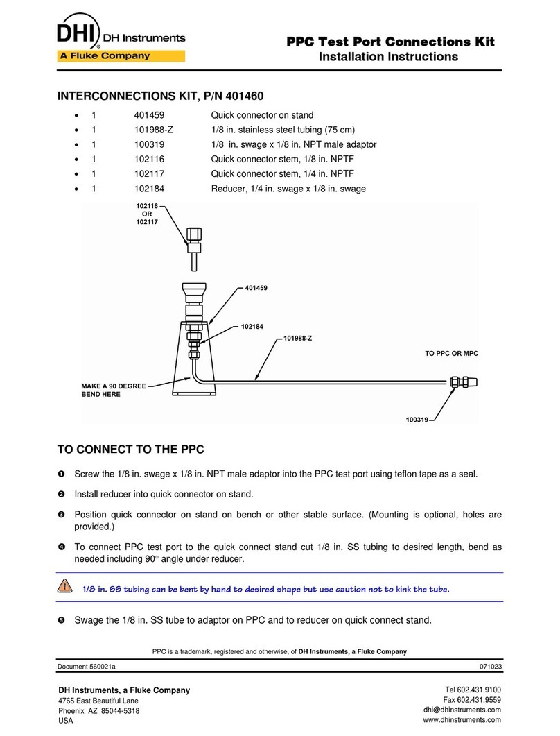
Blue Point Engineering RX-8 User manual

Copyright © 2011 Blue Point Engineering All Rights Reserved
Blue Point
Wireless Radio Control of Puppets
Engineering Inc.
RF Control C
Pointing the Way to Solutions!
Hardware Setup Overview
Blue Point Engineering Inc. Phone (303) 651-3794www.BPEsolutions.com
For more information on these products or to place an order
Page 1
RF
Transmitters
RX-8
RX8-PT
RX-LT
RX8-ch1,2
RX8-ch3,4
On/Off
Switch Board
Control Signal
Line Power Line
DC Voltage
RX8-ch1-8
VDC
Setup Overview
No.1
No.2
9VDC
Battery
2600 mAh
RF Receiver
Servo
Board
WIZ-12
Servo
Board
WIZ-12
Servo
Servo
Servo
Relay
Driver
Board
DB-SRD

Page 2
Copyright © 2011 Blue Point Engineering All Rights Reserved
RX8-PT
RX-LT
RX-8
RF Receiver
Board
SRD Board Power / On Off -
Distribution Board
Battery
Servos
Servo Driver
Board (Wiz12)
Servo Driver
Board (Wiz12)
Power Connector Battery
Power Connector Hook-up
Wire
COMPONENTS / PARTS
RF Long Range
Transmitter
RF Short Range
Key fob
Transmitter
9VDC @ 2.4 Amps
2.1 x 5mm Power
Jack (Male)
2.1 x 5mm
Power Jack
(Female)
3 Wire ( Black - Red - White )
Center
Positive
Center Positive
Ribbon Cable
with Connectors

Page 3
Copyright © 2011 Blue Point Engineering All Rights Reserved
RX8-PT
RX-LT
RX-8
SRD
Servo Driver
Board (Wiz12)
Ribbon
Connector
RX8 to SRD Board

Page 4
Copyright © 2011 Blue Point Engineering All Rights Reserved
RX8-PT
RX-LT
+
W
-
-
+
W
Servo No.1
Board (Wiz12)
+-
W
+-
W
Control Wire Setup
Servo No.2
Board (Wiz12)
- Black
- Red
- Yellow / White
R/C Servo
Connection
Standard +5 Vdc
R/C Servo
W
R
B
W
R
B
R/C Servo Setup
RX-8
SRD
Hook-up
Wire
See Operation Manual for info
on programming Wizard-12
Board Servo Travel Limits
Cut to needed
length
R/C Servo
Connection
R/C Servo
Connection
Servo No 1

RX8-PT
RX-LT
Page 5
Copyright © 2011 Blue Point Engineering
All Rights Reserved
Servo No.1
Board (Wiz12)
Power Setup
-
+
Black Wire = Power - (Negative)
Red Wire = Power + (Pluse)
CAUTION:
+ Power
- Power
-
+To Servo No.2
Board (Wiz12)
Battery
Power Plug
Adapter
Battery Power Cable
-
+
RX-8
-+
SRD
On/Off Switch
Optional
Power out
to RX8
Power Board
- OR -
(With Battery Accessories)
(With Battery Accessories)
-
+
2.1 x 5mm
Power Jack
2.1 x 5mm
Power Jack

RX8-PT
RX-LT
Page 6
Copyright © 2011 Blue Point Engineering
All Rights Reserved
SRD Board Overview
Ribbon Cable
SRD Board
To Servo Driver
Board-1 (Wiz12)
SS Relay Output Switch -Ch 5
Servo 1 Power
Connector + / -
Board Power Connector
2.1 5mm Power jack
(Center Positive +)
To Servo Driver
Board-2 (Wiz12)
Servo 2 Power
Connector + / -
SS Relay Output Switch -Ch 7
SS Relay Output Switch -Ch 6
SS Relay Output Switch -Ch 8
Servo / Relay Driver Board
Aux Power Connection
( RX8) + / - LED Status Light (Ch8)
Solid State Relay IC
Wire Terminal Block
Wire Secure Holes / Wire Tie
Mp3 Audio
Playback Module
LED Lighting
Effects Modules
Special Effects
Modules
SS Relay Closure
Output ON/OFF
Optional
Wires
Optional
To RX8 Board Connector
(Signal / Power)
Servo / Relay Driver Board
Mounting
Holes
CH-1,2
CH-3,4

RX8-PT
RX-LT
Page 7
Copyright © 2011 Blue Point Engineering
All Rights Reserved
RX-2 Overview
Board Power Connector
2.1 5mm Power jack
(Center Positive +)
Ribbon Cable to
SDR Board
Switch ON / Off DIP
Switches to Set Servo Travel
Movements
Left - Center - Right
Right - Center - Left
Left- Center
Right-Center
Servo Movements
Ch On/Off Status LED
RX Receiver to Hand Held Transmitter
LEARN Button
Adjustable
0-5 VDC Output Per Channel 1-8
(Switched ON / Off - Hand Transmitter)
Relay Outputs 5-8
Servo No.2
Servo No.1
Servo Playback
Optional
RF signal

Instruction I
Blue Point
Pointing the Way to Solutions!
Engineering www.BPEsolutions.com
Copyright © 2011 Blue Point Engineering Inc. , All Rights Reserved
Set - Up / Servo Travel
Servo Travel Adjustment
Wizard - 12
Wizard - 12
Controller
W
+
Rotational
Potentiometer
Interface Board
-Black
Wire
Red
Wire
White
Wire
+
-
Rotate
W
+-
Check Wire Connections
for correct polarity
CAUTION
-
+
POTENTIOMETER
10k Ohm
W
Optional
Connector
(M/F)
Wizard - 12
Controller
(+) Red Wire
(-) Black Wire
Power
Connection
9 Vdc @ 1 Amp
+ Vdc
center
- Vdc
outside
2.1 x 5mm
Power Jack
Power Connection
Wall or Battery Supply
- Black
- Red
- White
Caution
Check Wire Connections
for correct polarity
Wall Plug Power Supply
9 Vdc @ 1.0 Amp

Instruction I
Blue Point
Pointing the Way to Solutions!
Engineering www.BPEsolutions.com
Copyright © 2011 Blue Point Engineering Inc. , All Rights Reserved
Wizard - 12
Set - Up / Servo Travel
Servo Travel Adjustment
-+
R/C Servo
Connection
- Black
- Red
- White
Servo (-)
Servo (+)
Servo (S)
Caution
Check Correct
Servo Connection
Power
Connection
+ Vdc
center
- Vdc
outside
Wall Plug Power Supply
9 Vdc @ 1.0 Amp
2.1 mm
B/C
A +/-
C/B
Upper Servo
Travel Range
JP2
Configuration
Jumper Block
Momentary Short
Jumper Block OFF
when operating
Controller
JP1
Configuration
Jumper Block
Momentary Short
Jumper Block OFF
when operating
controller
Lower Servo
Travel Range
Potentiometer
Connection Terminal
POTENTIOMETER
W-+
W
See Servo Travel Calibration guide on using
the Jumper Blocks for setting the Upper and
Lower Servo Travel Movements
Rotational
R/C Servo
WBR
Optional
Connector
Analog
Servo
Travel Ranges (B-A-B)
B
R
W
2.1 x 5mm
Power Jack
Caution

Instruction I
Blue Point
Pointing the Way to Solutions!
Engineering www.BPEsolutions.com
Copyright © 2011 Blue Point Engineering Inc. , All Rights Reserved
Wizard - 12 Servo Travel Calibration
- Black
- Red
- White
Servo Travel Calibration
Troubleshooting:
Q. I am having trouble getting the servo to move when I adjust the potentiometer.
A1. Reset the Servo Lower and Upper Limit Ranges:
Temporarily short JP1 pin pain set or JP2 pin pair set by placing a jumper onto the pin pair for a
few seconds, then remove the jumper.
A2. Check to see that the Potentiometer has been wired correctly to the control board
terminal block. Wires +, - and W. Does the Wizard-12 board have power?
A3. Check to see if the servo is designed to move only a set amount (See servo
information specifications from manufacture on servo)
Connect a potentiometer, servo and power supply to the Wizard-12
controller board.
Adjusting the potentiometer will control the position of the attached servo.
The full range of the potentiometer and board electronics will generate
pulse width equivalent to a 180-degree servo movement. (1ms - 2ms)
Some servos will not accommodate this movement range. so take care
not to drive the servo into its limit stops at the extreme setting range.
Servo Travel Servo
Travel
JP1 JP1
Upper Servo
Travel Range
Setting the Servo Movement / Travel Range
Upper Limit Range:
Adjust the potentiometer and move the servo output
travel to the upper range point that you want the servo
to stop at. Temporarily short the JP1 pin pair set by
placing the jumper onto the pin pair for a few seconds,
then remove the jumper. This will record in memory the upper movement
travel range limit. This setting will be retained even after the power is turned
off, and will stay in memory until manually reset to a new range.
Lower Limit Range:
Adjust the potentiometer and move the servo output travel to the lower range
point that you want the servo to stop at.
Temporarily short the JP2 pin pair set by placing the jumper onto the pin pair
for a few seconds, then remove the jumper.
This will record in memory the upper movement travel range limit. This setting
will be retained even after the power is turned off, and will stay in memory until
manually reset to a new range. JP2 JP2
Lower Servo
Travel Range
JP2 JP1
JP1
-OR-
JP2
To RESET the Servo Lower and Upper Travel Limit Ranges:
Temporarily short JP1 pin pair set or JP2 pin pair set by placing a jumper onto
the pin pair for a few seconds, then remove the jumper. This will reset the servo
movement travel limit values recorded in memory to a 0 value allowing the servo
to move the full travel range of the servo.
(Note: some servos move only small travel ranges, as manufactured. For max
travel, select a servo that has the desired travel ranges you need)
Note: If the servo does not move as the potentiometer is adjusted, it may be that the upper and
lower limit travel ranges are overlapping. Try re setting the limits again or RESET the limit settings and
start again with the servo limits
Wiz-12
Potentiometer
RESET

4
Instruction I
Blue Point
Pointing the Way to Solutions!
Engineering www.BPEsolutions.com
Set - Up / Changing Address
RF Handheld Modules
RX-8 RF System
Using a paper clip, press the CREATE button down on the RF handheld Transmitter through the hole in the back of the
case. A LED will now light up indicating that the new address is being created. The address will be randomized for as
long as the button is held down. Release the button and the new randomized address will be activated. The LED will
begin flashing to indicate that the Control Permission Buttons access may now be set. Press the buttons 1-8 on the
front of RF handheld transmitter. Press the CREATE button with the paper clip again to record you actions. A new
button address and Control Permissions are now set in the RF handheld Transmitter. The RF Receiver board will
now need to learn the address before it will accept any handheld button transmissions.
The RF Long Range Handheld Transmitter allows the selection of one of 16,777,216 (2 ) unique addresses. All
Transmitters come ready to go with an address preset. To avoid conflict with other units or to create your own unique
address or add additional RF Receiver boards, you will need to change the RF handheld Transmitter and RF Receiver
board address.
24
Press
CREATE
button Flashing
LED Press
Control Permission
Buttons 1-8
Press
CREATE
button
(Paper clip)
1-8
1234
STEPS
(Paper clip)
Press the LEARN button down momentarily on the RF Receiver board. The Yellow LED will begin flashing indicating that
the Receiver board is ready to learn the new handheld Transmitter addresses. Press buttons 1-8 on the front of the RF
handheld Transmitter. Press the LEARN button down momentarily on the RF Receiver board again to record the actions
of the handheld Transmitter buttons. The RF Receiver board is now ready to recognize the handheld Transmitter buttons
and turn on the corresponding output channels 1-8 when activated by the handheld Transmitter. Test the system by
pressing a button on the RF handheld Transmitter; a corresponding output on the RF Receiver board should be activated
1-8 (LED- Green ON).
RF Long Range Handheld Transmitter
RF Receiver Board - 8 Channel
RX8
Receiver
Board
1
STEPS 23
Press
Buttons
1-8 Press
LEARN
Button
Press
LEARN
Button
Yellow LED Copyright © 2011 Blue Point Engineering Inc.
All Rights Reserved
Green
LED's
TEST
Long Range Handheld Transmitter
5
Teach RF
Receiver
new
Address

BATTERY REPLACEMENT
The LR remote unit utilizes a standard CR2032 Lithium Button Cell . In normal use, it will provide 1 to 2 years
of operation. To replace the battery, remove the access cover by pressing firmly down on the area and sliding it
off. Once the unit is open, remove the battery by sliding it from beneath the holder. There may be the risk of
explosion if the battery is replaced by the wrong type. Replace it with the same type of battery while observing
the correct battery +/- polarity.
Blue Point
Pointing the Way to Solutions!
Engineering
Copyright © 2011 Blue Point Engineering Inc.
All Rights Reserved
Set - Up / Battery - Transmission
RF Handheld Modules
RX-8 RF System
RF Transmitter and Receiver CONSIDERATIONS
Only one Transmitter at a time can be activated within a reception area. While the Transmitted signal consists of
encoded digital data, only one carrier of any particular frequency can occupy airspace at any given time. If two
identical Transmitters are activated in the same area at the same time, then the signals will interfere with each other
and the decoder will not see a valid transmission if the address is the same. NOTE: Two Receiver boards or more can
be activated at the same time and share a common RF handheld Transmitter address or two Transmitters of different
addressing and associated Receiver boards can be used in the same reception area with no interference issues usually.
CR2032 lithium button cell
CAUTION: Observe battery polarity
Battery +
(Plus) UP
Slide Out
Press
Down
Open Battery
Case Cover
Battery
Key Fob Handheld
Transmitter
(1-5) Buttons
Long Range
(LR) Handheld
Transmitter
1-8 Buttons
RF Receiver Board 1
RF Receiver Board 2
Address 1
Address 2
Address 1 -OR - Address 3
Address 3
Address 2 -OR - Address 3
Address 3
LR Remote
Channels 6-8 Not Available
Instruction I
www.BPEsolutions.com

Instruction I
Blue Point
Pointing the Way to Solutions!
Engineering www.BPEsolutions.com
Set - Up / Changing Address
RF Handheld Modules
RX-8 RF System
Using a paper clip, press the ADD button down on the RF handheld Transmitter through the hole in the back of the case.
The address will be randomized for as long as the button is held down. Release the button and the new randomized
address will be activated. Press the buttons 1-5 on the front of RF handheld Transmitter. Press the ADD button with
the paper clip again to record you actions or wait 17 seconds for it to time out. A new button address and Control
Permissions are now set in the RF handheld Transmitter. The RF Receiver board will now need to learn the address
before it will accept any handheld Key Fob button transmissions 1-5.
The RF Key Fob Handheld Transmitter allows the selection of one of 16,777,216 (2 ) unique addresses. All
transmitters come ready to go with an address preset. To avoid conflict with other units or to create your own unique
address or add additional RF receiver boards, you will need to change the RF handheld Transmitter and RF receiver
board address.
24
Press
Control
Permission
Buttons 1-5(Paper clip)
Press
Down
Add
button
1
2
3
STEPS
Press the LEARN button down momentarily on the RF Receiver board. The Yellow LED will begin flashing indicating that
the Receiver board is ready to learn the new handheld Transmitter addresses. Press buttons 1-5 on the front of the RF
handheld Transmitter. Press the LEARN button down momentarily on the RF Receiver board again to record the actions
of the handheld Transmitter buttons. The RF Receiver board is now ready to recognize the handheld Transmitter buttons
and turn on the corresponding output channels 1-5 when activated by the handheld Transmitter. Test the system by
pressing a button on the RF handheld Transmitter; a corresponding output on the RF Receiver board should be activated
1-5 (LED- Green ON). NOTE: LED's 6-8 and Channels 6-8 Not used with Key Fob Transmitter
RF Key Fob Handheld Transmitter
RF Receiver Board - 8 Channel
RX8
Receiver
Board
1
STEPS 234
Press
Buttons
1-5 Press
LEARN
Button
Press
LEARN
Button
Yellow LED
Copyright © 2011 Blue Point Engineering Inc. All Rights Reserved
Green
LED's 5TEST
Press
Down
Add
button
Key Fob Handheld Transmitter
NOTE: Channels 6-8 Not used
with Key Fob Transmitter
4
Teach RF
Receiver
new
Address
Channels 6-8 Not Available

INSTRUCTION TO THE USER
FCC compliance
This device complies with Part 15 of the FCC Rules.
Operation of this device is subject to the following two conditions:
(1) This device may not cause harmful interference, and
(2) this device must accept any interference received, including interference that may cause
undesired operation.
This equipment has been tested and found to comply with the limits for a Class B
digital device, pursuant to Part 15 of the FCC Rules. These limits are designed to
provide reasonable protection against harmful interference in a residential installation. This
equipment generates, uses and can radiate radio frequency energy and, if not installed and
used in accordance with the instructions, may cause harmful interference to radio
communications. However, there is no guarantee that interference will not occur in a particular
installation. If this equipment does cause harmful interference to radio or television reception,
which can be determined by turning the equipment off and on, the user is encouraged to try
to correct the interference by one or more of the following measures:
Reorient or relocate the receiving antenna.
Increase the separation between the equipment and receiver.
Connect the equipment into an outlet on a circuit different from that to which the receiver is
connected.
Consult the dealer or an experienced radio/TV technician for help.
This equipment has been certified to comply with the limits for a Class B computing device,
pursuant to FCC Rules. In order to maintain compliance with FCC regulations, shielded
cables must be used with this equipment. Operation with non-approved equipment or
unshielded cables is likely to result in interference to radio and TV reception. The user is
cautioned that changes and modifications made to the equipment without the approval of
manufacturer could void the user’s authority to operate this equipment.
Instruction I
Blue Point
Pointing the Way to Solutions!
Engineering www.BPEsolutions.com
FCC Compliance, Certification
RF -Transmitter 418MHz
RX-8 RF System
FCC ID: OJM-OTX-XXX-LRMSA
IC: 5840-LRMS-XXXA 418MHz
Long Range Handheld RF Transmitter (8 CH)
FCC ID: OJM-OTX-XXX-KFMSA
IC: 5840A-KFMS-XXXA 418MHz
Key Fob Handheld RF Transmitter (5 CH)
Copyright © 2011 Blue Point Engineering Inc. , All Rights Reserved
Table of contents
Other Blue Point Engineering Cables And Connectors manuals
