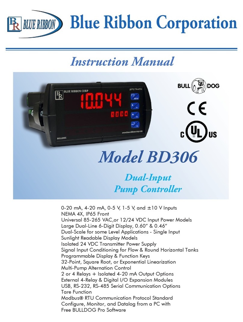
Blue Ribbon BB4000 User manual

Blue Ribbon Corporation
Instruction Manual
Model BB4000
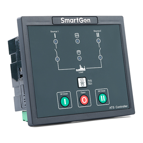
Station Controller
Blue Ribbon Corp
2770 Long Road
Grand Island, NY 14072
Ph: 716-773-9300
email: [email protected]
Website: www.blueribboncorp.com
DISCLAIMER: No representations or warranties are made with respect to the contents of this Instruction Manual. Blue Ribbon Corp
reserves the right to revise this manual and to make changes periodically to the content thereof, without obligation
to notify any persons of such revisions.

Model 311 Hazardous Approved Installation Manual
Table of Contents
1. IntroductIon . . . . . . . . . . . . . . . . . . . . 1
1.1. Applications. .................................1
1.2. Standard Features. ............................1
1.3. Optional Features..............................1
1.4. Specications. ................................1
1.5. Ordering Information...........................2
2. operator Interface functIons . . . . . . . . . . . 3
2.1. How to View a Setup Parameter Value. ............3
2.2. How to Change a Setup Parameter Value. ..........3
2.3. How to Simulate Levels..........................4
2.4. How to Enter the Security Code. ..................4
3. Menu - systeM setup . . . . . . . . . . . . . . . . 5
4. Menu - data dIsplay. . . . . . . . . . . . . . . . 10
5. puMp call sequence - setup paraMeters . . . . . 12
5.1. Number of Pumps Present - Parameter P.13. .......12
5.2. Number of Pumps Allowed to Run at the Same Time - Parameter P.14.
12
5.3. Number of Pumps Allowed to Run On Generator - Parameter P.15. 12
5.4. Alternator Sequence Mode - Parameter P.16. .......13
6. puMp call sequence - setup paraMeters . . . . . 13
6.1. Pump Stop Mode - Parameter P.17................13

Model 311 Hazardous Approved Installation Manual
6.2. Automatic Alternation - Parameter P.18............14
6.3. Forced Lead Pump Position - Parameter P.39.. . . . . . . 14
6.4. Time Based Alternation - Parameter 5.1. ..........14
7. alternatIon sequence Mode . . . . . . . . . . . 15
7.1. Standard Alternation Parameter P.16-1. .........15
7.2. Pump 1 Always Lead...........................15
7.3. Pump 1 Always Lead...........................16
7.4. Split Alternation Parameter P.16 = 4. ...........16
7.5. Fixed Alternation Parameter P.16 = 5. ...........17
7.6. Stepped On/Off Sequence. .....................17
8. dIscrete Input functIons . . . . . . . . . . . . . 18
8.1. Pump 1 (2, 3, 4) Disable - Functions 1-4. ..........18
8.2. Level Freeze - Function 5. ......................18
8.3. External Alternation - Function 6. ................18
8.4. On Generator - Function 7. .....................19
8.5. All Pump Disable - Function 8. ..................19
8.6. Sequence Input 1 (2, 3, 4) - Functions 9 - 12........19
8.7. Call Pump 1 (2, 3, 4) Last - Functions. .............19
8.8. Low Level Alarm - Function 17. ..................19
8.9. High Level Alarm - Function 18. .................20
8.10. Telemetry E - D - Functions 19 - 30.. . . . . . . . . . . . . . 20
8.11. Normal Pump Operation Disable - Function 31......20
8.12. Float Backup - Lower Level - Function 32. .........20
8.13. Float Backup - Off Level - Function 33. ...........21
8.14. Float Backup - 1st On Level - Function 34. ........21
8.15. Float Backup - 2nd On Level - Function 35. .......21
8.16. Float Backup - 3rd On Level - Function 36.........21

Model 311 Hazardous Approved Installation Manual
8.17. Float Backup - 4th On Level - Function 37. ........21
8.18. Float Backup - High Level - Function 38. .........22
8.19. Start Flush Cycle - Function 39. .................22
9. systeM status . . . . . . . . . . . . . . . . . . . 22
9.1. High Level Alarm. ............................22
9.2. Low Level Alarm. .............................23
9.3. Power Indication..............................23
9.4. Fault Indication...............................23
9.5. Fault Code - Parameter FLC. ....................23
9.6. Last Fault Code - Parameter LFC. ................24
9.7. Fault Code Table. .............................25
10. analog level Input (4-20 Ma Input)- calIbratIon procedure
27
10.1. Level Input Zero - Parameter P.25. ...............27
10.2. Level Input Span - Parameter P.24..............27
10.3. Level Display Span VS. Transducer Calibration. ..28
11. varIable frequency drIve speed control optIon setup
29
11.1. VFD Speed Control - Setup Parameters. ...........29
12. flush cycle . . . . . . . . . . . . . . . . . . . 30
12.1. Flush Cycle Steps:. ............................30
12.2. Automatically Starting Flush Cycle:. ..............30
12.3. Manually Starting / Stopping Flush Cycle:. .........31
12.4. Flush Cycle - Setup Parameters. .................31

Model 311 Hazardous Approved Installation Manual
13. flow calculator . . . . . . . . . . . . . . . . . 32
13.1. Latest Inow Rate - The Most Recently Determined Flow Rate into the Lift Station.32
13.2. Average Daily Inow Total - The Flow Totals from the Last 7 days Averaged Together.
32
13.3. Pump Outow Rate - The Most Recently Determined Outflow Rate of Each Pump.
32
13.4. Flow Calculator - Setup Parameters. ..............33
13.5. Flow Calculator - Surface Area Calculation. ........34
13.6. Flow Calculator - Display Parameters. ............34
14. coMMunIcatIon wIth ascada systeM . . . . . 35
14.1. MODBUS Functions Supported. ..................35
14.2. Setup for Connection to a SCADA System. ..........35
15. rs232 serIal port . . . . . . . . . . . . . . . . 36
16. ethernet port - optIon . . . . . . . . . . . . . 37
16.1. Features. ...................................37
16.2. Setup of Ethernet Port..........................37
17. scada regIsters . . . . . . . . . . . . . . . . 38
18. scada features . . . . . . . . . . . . . . . . . 42
18.1. Level. 42
18.2. Discrete Inputs. ..............................42
18.3. Auxiliary Analog Input Data.....................43
18.4. Pump On / Off and Alarm Levels. ................43
18.5. Disabling Pump Operation......................43
18.6. Forcing a Pump On. ...........................43
18.7. Setting Speed of Pumps Forced On. ..............44

Model 311 Hazardous Approved Installation Manual
18.8. Forcing Pump Alternation.......................44
18.9. Forcing Lead Pump Position. ....................44
18.10. Remote Control of Relays.................44
18.11. Flush Cycle. ...........................45
18.12. Flow Calculator Data. ...................45
18.13. High Level Telemetry. ...................45
18.14. Low Level Telemetry.....................45
18.15. Fault Codes. ..........................46
18.16. Pump Speed Reference. .................46
18.17. Elapsed Time Meters. ...................46
19. scada trouble shootIng . . . . . . . . . . . 46
19.1. Communication Activity Indicator. ................46
19.2. Address of Last Slave Polled by Master. ...........47
19.3. Record of Last Modbus Message. ................47
19.4. Communication Fault Codes. ....................47
20. connectIon dIagraM. . . . . . . . . . . . . . . 48
20.1. Standard Features. ...........................48
20.2. Connection Diagram - Optional Analog I/O. .......49
20.3. Connection Diagram - Lead Pump Selector Switch. ..50
20.4. Connection Diagram - Analog Level Input . ........51
20.5. Connection Diagram - Level Probe. ..............52
20.6. Level Probe - Placement and Setup. ..............53
20.7. Control Schematic Example. ....................54
20.8. Float Backup Example - Pump Down. .............55
20.9. Operator Interface. ...........................57
20.10. Enclosure Mechanical Layout. ............58
20.11. Panel Cutout. .........................59
21. warranty. . . . . . . . . . . . . . . . . . . . . 60

1
Model BB4000 Controller Instruction Manual
1. IntroductIon
1.1. Applications
Simplex, Duplex, Triplex, or Quadraplex
Liquid Level Control
Pump Down (Empty a Tank) or Pump Up (Fill
a Tank)
Fixed or Variable Speed Control
Where Connection to a SCADA System is
Required
1.2. Standard Features
All Setup Parameters Values may be viewed or
changed from the front of the unit.
Level Input Source - Menu Selectable:
–Analog Level Input [4-20mA from
Pressure Transducer]
–Level Probe [Conductance Probe with
10 Electrodes]
Regulated +20Vdc power for Analog Level
Input
RS-232 Serial Port with Modbus RTU Protocol
High and Low Level Alarm Relays and Alarm
Indication
Adjustable lag Pump(s) Delay
Alternation Schemes - Menu Selectable:
–Standard Alternation
–Pump 1 Always Lead - Stays On with
other Pumps
–Pump 1 Always Lead - Turns Off with
other Pumps On
–Split Alternation - Pumps 1&2, and
Pumps 3&4
–Fixed Sequence - Pump 1 Always Lead
–Stepped On/Off - Only One Pump
Runs at a Time
Alternator Logic Skips Disabled Pumps
First On - First Off or First On - Last Off
Alternation
Level Simulation (Automatically ends after 1
minute)
Security Code Protected Parameter Setup
18 Discrete Inputs programmable for the
following functions:
–Pump disable with HOA in OFF, or
pump fault
–External Lead Pump Selector Switch
–All pump disable - for connection to
Phase Monitor
Return to Table of Contents
–Limit number of pumps called while on
emergency power
–Alternation by External Time Clock
–Freeze wet well level during a bubbler
tube purge
–Call pump last
–Float switch backup
–Low Level Pump Cutoff
–Start Flush Cycle
–A variety of SCADA functions
Status of Discrete Inputs may be viewed from
front of Controller
Backup Control, and High & Low Alarms using
a Level Probe
Output Relays may be programmed for control
through SCADA
Automatic Flush Cycle to reduce sludge build up
Flow Calculator that provides the following Flow
Data:
–Latest Inflow Rate
–Average Daily Inflow Total (Average of Last
7 Days)
–Pump Outflow Rate (Latest for Each Pump)
1.3. Optional Features
Up to four Isolated 4-20mA Analog Outputs
that may be used for VFD speed control or for
sending out a copy of the Level Input
Up to four Isolated 4-20mA Auxiliary Analog
Inputs that may be used to collect analog data
for SCADA
4-20mA Analog Level Input may be ordered as
an Isolated Input
Ethernet Port with the following Protocols:
Modbus TCP or Modbus RTU
1.4. Specications
Input Power: 120 VAC ±10%, 13 VA max
External Dimensions: 6.9”x 8.5”x 4.9”
Agency Approvals: UL 508, CAN/CSA
Ambient Operating Temperature:
Without Analog Outputs:
-20 °C to +65 °C (-4 °F to +149 °F)
With Analog Outputs:
-20 °C to +50 °C (-4 °F to +122 °F)
Level Display: 3 Digit, 7 Segment LED

2
Model BB4000 Controller Instruction Manual
Return to Table of Contents
Level Display Range: 0-999 feet
(Decimal Point Position is Selectable)
Indicators: LED
Color: White with Blue Lettering
Relays: 6A @ 250VAC
Analog Level Input: 4-20mA, 250Ω Load, Transient Protected
Level Probe Inputs: ±8V, 60Hz Square Wave ±0.8mA max, Transient Protected
Discrete Inputs: 24Vdc, Transient Protected
Power for Discrete Inputs: Unregulated +24Vdc, Transient Protected
Power for Analog Level Input: Regulated +20Vdc ±1V, Transient Protected
Analog Outputs: Isolated 4-20mA Maximum Load Resistance: 600Ω
Auxiliary Analog Inputs: Isolated 4-20mA, 250Ω Load, Transient Protected
1.5. Ordering Information
Part Number: BB4000 - X X X X
Number of Optional
Analog Outputs:
0 = Zero Analog Outputs
1 = One Analog Output
2 = Two Analog Outputs
3 = Three Analog Outputs
4 = Four Analog Outputs
Number of Optional
Auxiliary Analog Inputs:
0 = Zero Auxiliary Analog Inputs
1 = One Auxiliary Analog Input
2 = Two Auxiliary Analog Inputs
3 = Three Auxiliary Analog Inputs
4 = Four Auxiliary Analog Inputs
Blank = RS232 Port
E = RS232 Port & Ethernet Port
Blank = Non-Isolated Analog Level Input
S = Isolated Analog Level Input

3
Model BB4000 Controller Instruction Manual
Return to Table of Contents
2. operator Interface functIons
2.1. How to View a Setup Parameter Value
1. Press push-button PB-M until the Menu Scroll Mode indicator comes on.
2. Press push-button PB-D and PB-U as needed to arrive at the desired Parameter view.
3. Parameters Shown on Front of Controller:
The value of the Parameter is displayed
whenever the indicator next to the Para-
meter label is on.
Parameters in the System Setup Sub-Menu:
The value of the Parameter in the System Setup Sub-Menu may be
viewed by using the push-button PB-M to toggle from the Parameter
number (P. 13, for example) to the Parameter value.
2.2. How to Change a Setup Parameter Value
1. Press push-button PB-M until the Menu Scroll mode indicator comes on.
2. Press push-button PB-D and PB-U as needed to arrive at the Parameter you wish to
change.
3. Parameters Shown on Front of Controller:
Press Push-button PB-M until the Value change indicator comes on.

4
Model BB4000 Controller Instruction Manual
Return to Table of Contents
Parameters in the System Setup Sub-Menu:
Press push-button PB-M until the Value Change indicator comes
on. The current value of the Parameter will then be displayed.
4. Press and hold for 4 seconds, either push-button PB-D or PB-U, to change the Para-
meter to the desired new value. (If the Parameter values will not change, they may be
locked. See directions below to un-lock Parameters.)
5. Press push-button PB-M or PB-L to exit the Value Change mode.
2.3. How to Simulate Levels
1. Press push-button PB-S.
Note: The Simulation starts from the actual level displayed prior to entering the
Level Simulation mode.
2. Press push-button PB-D or PB-U as needed to change the simulated level.
3. To end the level simulation press push-button PB-L.
Note: If you do not exit the Level Simulation mode, normal operation will resume
automatically 60 seconds after the last time the PB-U, PB-D, or PB-S push-buttons
were pressed.
2.4. How to Enter the Security Code
1. Press the push-button PB-M until the Menu Scroll mode indicator comes on.
2. Press push-button PB-U until the display reads SEC.
3. Press push-button PB-M to change to the Value Change mode.
4. Press and hold for 4 seconds, either push-button PB-D or PB-U, to change the value
displayed to that of the correct security code.

5
Model BB4000 Controller Instruction Manual
3. Menu - systeM setup
Return to Table of Contents
Parameter Default
Value
Current
Value Setting DefinitionS
- 2.0 ft Low LevelAlarm SCADARegister 40021 Range: 0.1 - 99.9 ft
Note: To DisableAlarm, see Parameter P.50.
- 3.0 ft 1st Pump Off Level SCADARegister 40013 Range: 0.2 - 99.9 ft
- 6.0 ft 1st Pump On Level SCADARegister 40012 Range: 0.2 - 99.9 ft
- 4.0 ft 2nd Pump Off Level SCADARegister 40015 Range: 0.2 - 99.9 ft
- 7.0 ft 2nd Pump On Level SCADARegister 40014 Range: 0.2 - 99.9 ft
- 4.5 ft 3rd Pump Off Level SCADARegister 40017 Range: 0.2 - 99.9 ft
- 8.0 ft 3rd Pump On Level SCADARegister 40016 Range: 0.2 - 99.9 ft
- 5.0 ft 4th Pump Off Level SCADARegister 40019 Range: 0.2 - 99.9 ft
- 9.0 ft 4th Pump On Level SCADARegister 40018 Range: 0.2 - 99.9 ft
- 10.0 ft High LevelAlarm SCADARegister 40020 Range: 0.5 - 99.9 ft
- 5 sec. Lag Pump(s) Delay Range: 1 - 100 seconds
SEC 0Security Code - Enter Your Security Code Here toAllow Parameters to be
Changed. Change to other Number to Re-lockAll Parameters.
Note: The Security Code may be Customized using Parameter P.26. See Page 6.
P.13 4Number of Pumps Present See Page 12.
1 = 1 Pump 2 = 2 Pumps 3 = 3 Pumps 4 = 4 Pumps
P.14 4Number of PumpsAllowed to Run at the Same Time See Page 12.
1 = 1 Pump 2 = 2 Pumps 3 = 3 Pumps 4 = 4 Pumps
P.15 4Number of PumpsAllowed to Run On Generator See Page 12.
1 = 1 Pump 2 = 2 Pumps 3 = 3 Pumps 4 = 4 Pumps
Note: Must Connect Transfer Switch Contacts to Discrete Input Programmed for Function 7.
P. 16 1
Alternator Sequence Mode
1 = StandardAlternation See Page 15.
2 = Pump 1Always Lead - Stays On With Other Pumps See Page 15.
3 = Pump 1Always Lead -Turns Off With Other Pumps See Page 16.
4 = SplitAlternation - Pumps 1&2, and Pumps 3&4 See Page 16.
5 = Fixed Sequence - Pump 1Always Lead See Page 17.
6 = Stepped On/Off - Only One Pump Runs at a Time See Page 17.
P.17 2Pump Stop Mode See Page 13.
1 = First On Last Off 2 = First On First Off
P.18 1AutomaticAlternation See Page 14.
1 = Enabled 2 = Disabled
P.19 1Pump Up or Down Mode
1 = Pump Down - Empty a Tank 2 = Pump Up - Fill a Tank
Note: When Parameter P.19 is Changed, New Default Level Parameter Values will be Loaded.
P.20 - P.23. - VFD Speed Control Setup See Page 29.
All Level Settings Have the Decimal Point Artificially Inserted Based on Parameter P.36.

6
Model BB4000 Controller Instruction Manual
Return to Table of Contents
Parameter Default
Value
Current
Value Setting DefinitionS
P.24 11.5 ft
Level Input Calibration - Span Range: 0.9 - 99.9 ft See Page 27.
Notes:
1. 20 mAis Typically Applied to theAnalog Input while Setting the Span.
2. Parameter P.24 Shows the Wet Well Level, while allowing the Up & Down
Push-buttons to Change the Internal Number used to Calculate the Displayed Level.
3. When Controller is set to Operate using a Level Probe, Parameter P.24 shows “77.7”.
P.25 0.0 ft
Level Input Calibration - Zero See Page 27.
Notes:
1. 40 mAis Typically Applied to theAnalog Input while Setting the Zero.
2. Parameter P.25 Shows the Wet Well Level, while allowing the Up & Down
Push-buttons to Change the Internal Number used to Zero the Displayed Level.
3. When Controller is set to Operate using a Level Probe, Parameter P.25 shows “77.7”.
P.26 0
Security Code Setup Parameter - Establishes What Value Will beAccepted as
the Security Code at Parameter SEC. Range: 0 - 255
Note:
1. To Change Parameter P.26, the Current Security Code Must First be Entered into SEC.
2. When You Change Parameter P.26 and Exit the Value Change Mode Parameter, P.26 Will
No Longer be Viewable, Until You Enter the New Security Code into Parameter SEC.
3. If You Forget Your Security Code, Consult the Factory for the Master Security Code.
P.28 1 SlaveAddress See Page 35.
P.29 - P.32 - RS232 Serial Port Setup See Page 36.
P.33 1 RegisterAccess Mode See Page 35.
P.35 1 sec. Stop Pump Delay Range: 1 - 100 seconds
Note: This is the Time Period that the Wet Well Level Must RemainAt or Below (At orAbove for
Pump UP P.19=2) the Respective OFF Level Setting in order to Turn Off a Pump.
P.36 1 Display Decimal Point Position 0 = No Decimal Point 1 - XX.X 2 = X.XX
P.37 1 min. Pump Re-enable Delay after Float Backup Low Level (High Level)
Notes: Range: 1 - 255 minutes
1. Pump Down (Parameter P.19 = 1) - Delay Starts when the Low Level Float Input Opens.
2. Pump Up (Parameter P.19 = 2) - Delay Starts when the High Level Float Input Opens.
P.38 1 min. Delay Canceling Remote Control Commands
Notes: Range: 0 - 254 minutes
1. Delay Starts when Serial Communication is Lost.
2. To Allow all Remote Commands to Remain in Effect (Until Power Loss) Set P.38 = 255.
P.39 0Forced Lead Pump Position SCADARegister 40022 See Page 14.
0 = NormalAlternation 1 (2, 3, 4) = Pump 1 (2, 3, 4) as Lead
P.40 - P.43 - Flush Cycle Setup See Page 31.
P.44 - P.47 - Flow Calculator Setup See Pages 33 - 34.
P.49 240 Analog Level Input - Signal Conditioning Control Range: 1 - 254
10 = Very Slow 100 = Slow 240 = Normal 250 = Fast
P.50 1Low LevelAlarm Mode 0 = Disabled 1 = Enabled
Note: Setting “0” Disables Low LevelAlarms from theAnalog Level Input or Level Probe Inputs.
P.51 0Time BasedAlternation Range: 1 - 255 1/6 hour See Page 14.
0 = Disabled 1 = 1/6 hour 6 = 1 hour 48 = 8 hours 144 = 24 hours
P.52 0 Pump 1 (2, 3, 4) Disable - Discrete Input Mode 0 = Normal 1 = Logic Inverted
FLC -Fault Code SCADARegister 40047 See Fault CodeTable on Pages 25-26.
Note: ThisAutomatically Returns to Zero when the Fault Clears (Except for Faults 20-29).
All Level Settings Have the Decimal Point Artificially Inserted Based on Parameter P.36.
Menu - SySteM Setup

7
Model BB4000 Controller Instruction Manual
Return to Table of Contents
Parameter Default
Value
Current
Value Setting DefinitionS
LFC -Last Fault Code SCADARegister 40048 See Fault Code Table on Pages 25-26.
Note: This is a Copy of the Last Non-Zero Fault Code that was shown on Parameter FLC.
oPr - Operating Program Revision Number - Controller SCADARegister 40063
EPr - Operating Program Revision Number - Ethernet Board
All Level Settings Have the Decimal Point Artificially Inserted Based on Parameter P.36.
Menu - SySteM Setup
F.01 1Discrete Input 1
Function Function of Input: Connect To:
F.02 2Discrete Input 2
Function 0 = No Function
1 = Pump 1 Disable . . . . . . . . . . . . . . . . . . . . . . . . . . . . . . . . . . . HOAand Fault Logic
2 = Pump 2 Disable . . . . . . . . . . . . . . . . . . . . . . . . . . . . . . . . . . . HOAand Fault Logic
3 = Pump 3 Disable . . . . . . . . . . . . . . . . . . . . . . . . . . . . . . . . . . . HOAand Fault Logic
4 = Pump 4 Disable . . . . . . . . . . . . . . . . . . . . . . . . . . . . . . . . . . . HOAand Fault Logic
5 = Level Freeze . . . . . . . . . . . . . . . . . . . . . . . . . . . . . . . . . Bubbler Tube Purge Logic
6 = ExternalAlternation . . . . . . . . . . . . . . . . . . . . . . . . . . . . . . . . .External Time Clock
7 = On Generator . . . . . . . . . . . . . . . . . . . . . . . . . . . . . . . . .Automatic Transfer Switch
8 =All Pump Disable . . . . . . . . . . . . . . . . . . . . . . . . . . . . . . . . . . . . . . . Phase Monitor
9 = Sequence Input 1 . . . . . . . . . . . . . . . . . . . . . . . . . .Lead Select Switch - 1 as Lead
10 = Sequence Input 2 . . . . . . . . . . . . . . . . . . . . . . . . .Lead Select Switch - 2 as Lead
11 = Sequence Input 3 . . . . . . . . . . . . . . . . . . . . . . . . .Lead Select Switch - 3 as Lead
12 = Sequence Input 4 . . . . . . . . . . . . . . . . . . . . . . . . .Lead Select Switch - 4 as Lead
13 = Call Pump 1 Last . . . . . . . . . . . . . . . . . . . . . . . . . . . . . . . . . . . . . . .Logic Contact
14 = Call Pump 2 Last . . . . . . . . . . . . . . . . . . . . . . . . . . . . . . . . . . . . . . .Logic Contact
15 = Call Pump 3 Last . . . . . . . . . . . . . . . . . . . . . . . . . . . . . . . . . . . . . . .Logic Contact
16 = Call Pump 4 Last . . . . . . . . . . . . . . . . . . . . . . . . . . . . . . . . . . . . . . .Logic Contact
17 = Low LevelAlarm . . . . . . . . . . . . . . . . . . . . . . . . . . . . . . . .Low Level Float Switch
18 = High LevelAlarm . . . . . . . . . . . . . . . . . . . . . . . . . . . . . . . High Level Float Switch
19 = Telemetry E . . . . . . . . . . . . . . . . . . . . . . . . . . . . . . . . . . . . . . . Telemetry Contact
20 = Telemetry F . . . . . . . . . . . . . . . . . . . . . . . . . . . . . . . . . . . . . . . Telemetry Contact
21 = Telemetry G . . . . . . . . . . . . . . . . . . . . . . . . . . . . . . . . . . . . . . .Telemetry Contact
22 = Telemetry H . . . . . . . . . . . . . . . . . . . . . . . . . . . . . . . . . . . . . . . Telemetry Contact
23 = Telemetry J . . . . . . . . . . . . . . . . . . . . . . . . . . . . . . . . . . . . . . . .Telemetry Contact
24 = Telemetry K . . . . . . . . . . . . . . . . . . . . . . . . . . . . . . . . . . . . . . . .Telemetry Contact
25 = Telemetry L. . . . . . . . . . . . . . . . . . . . . . . . . . . . . . . . . . . . . . . .Telemetry Contact
26 = Telemetry M . . . . . . . . . . . . . . . . . . . . . . . . . . . . . . . . . . . . . . . Telemetry Contact
27 = TelemetryA . . . . . . . . . . . . . . . . . . . . . . . . . . . . . . . . . . . . . . . .Telemetry Contact
28 = Telemetry B . . . . . . . . . . . . . . . . . . . . . . . . . . . . . . . . . . . . . . . .Telemetry Contact
29 = Telemetry C . . . . . . . . . . . . . . . . . . . . . . . . . . . . . . . . . . . . . . . Telemetry Contact
30 = Telemetry D . . . . . . . . . . . . . . . . . . . . . . . . . . . . . . . . . . . . . . . Telemetry Contact
31 = Normal Pump Operation Disable . . . . . . . . . . . . . . . . . . . . . . . . . . .Fault Contact
32 = Float Backup - Low Level . . . . . . . . . . . . . . . . . . . . . . . . .Low Level Float Switch
33 = Float Backup - Off Level . . . . . . . . . . . . . . . . . . . . . . . . . . .Off Level Float Switch
34 = Float Backup - 1st On Level . . . . . . . . . . . . . . . . . . . . .1st On Level Float Switch
35 = Float Backup - 2nd On Level . . . . . . . . . . . . . . . . . . . .2nd On Level Float Switch
36 = Float Backup - 3rd On Level . . . . . . . . . . . . . . . . . . . . 3rd On Level Float Switch
37 = Float Backup - 4th On Level . . . . . . . . . . . . . . . . . . . . .4th On Level Float Switch
38 = Float Backup - High Level . . . . . . . . . . . . . . . . . . . . . . . . High Level Float Switch
39 = Start Flush Cycle . . . . . . . . . . . . . . . . . . . . . . . . . . . . . . . . . .External Time Clock
Notes:
1. Function of Discrete Inputs may be set to “0” when Input is used only to
collect data for SCADAand no other Function is desired.
2. All Discrete Inputs may be read from SCADARegisters 40035 - 40037,
regardless of the Function assigned to the Input
3. See Pages 18-22 for description of each of the above Functions.
4. Pump 1 (2,3,4) Disable logic may be inverted. See Parameter P.52.
F.03 3Discrete Input 3
Function
F.04 4Discrete Input 4
Function
F.05 5Discrete Input 5
Function
F.06 6Discrete Input 6
Function
F.07 7Discrete Input 7
Function
F.08 8Discrete Input 8
Function
F.09 9Discrete Input 9
Function
F.10 10 Discrete Input 10
Function
F.11 11 Discrete Input11
Function
F.12 12 Discrete Input 12
Function
F.13 13 Discrete Input 13
Function
F.14 14 Discrete Input 14
Function
F.15 15 Discrete Input 15
Function
F.16 16 Discrete Input 16
Function
F.17 17 Discrete Input 17
Function
F.18 18 Discrete Input 18
Function

8
Model BB4000 Controller Instruction Manual
Return to Table of Contents
All Level Settings Have the Decimal Point Artificially Inserted Based on Parameter P.36.
Menu - SySteM Setup
Parameter Default
Value
Current
Value Setting DefinitionS
F.19 1
Level Input Source
1 =Analog Level Input (4-20 mA) on J21
2 = Level Probe Input on J25
3 = Level Probe Input on J25 (Flashes Level Probe Electrode No. of Level Settings.)
4 = Remote Level Input (Follows the Level written to SCADARegister 40025.)
Note: Level Probe not suitable for applications measuring Storm Water or Well Water.
F.20 12 in. Level Probe Electrode Spacing Range: 3 - 24 Inches
F.21 0.0 ft Level Offset Range: 0.0 - 5.0 ft
Note: This adds to the Level from theAnalog Level Input or Level Probe Input.
F.22 100 Level Probe Sensitivity Range: 90 - 210
100 - Typical Sewage 150 = Light Sewage
Check value of Parameter L.10 with Electrode 10 covered, add 40 to it, and enter value for F.22.
Note: Level Probe not suitable for applications measuring Storm Water or Well Water.
F.23 1 Analog Output 1 Function 1 = Pump 1 Speed (Active When Pump 1 is Called)
2 - Pump 2 Speed (Active When Pump 2 is Called)
3 - Pump 3 Speed (Active When Pump 3 is Called)
4 - Pump 4 Speed (Active When Pump 4 is Called)
5 - Speed Reference any Pump (AlwaysActive)
6 = Copy of Wet Well Level
F.24 2 Analog Output 2 Function
F.25 3 Analog Output 3 Function
F.26 4 Analog Output 4 Function
F.31 1HI Relay Output Function
0 = Disabled 1 = High LevelAlarm 2 = Remote Control (SCADACoil 25)
Note: High Level indicator on front of unit will operate regardless of setting.
F.32 1LO Relay Output Function
0 = Disabled 1 = Low LevelAlarm 2 = Remote Control (SCADACoil 26)
Note: Low Level indicator on front of unit will operate regardless of setting.
F.33 1P1 Relay Output Function
0 = Disabled 1 = Pump 1 Call 2 = Remote Control (SCADACoil 27)
Note: When set on “0” or “2” Pump 1 will be skipped over in allAlternation Sequence Modes.
F.34 1P2 Relay Output Function
0 = Disabled 1 = Pump 2 Call 2 = Remote Control (SCADACoil 28)
Note: When set on “0” or “2” Pump 2 will be skipped over in allAlternation Sequence Modes.
F.35 1P3 Relay Output Function
0 = Disabled 1 = Pump 3 Call 2 = Remote Control (SCADACoil 29)
Note: When set on “0” or “2” Pump 3 will be skipped over in allAlternation Sequence Modes.
F.36 1P4 Relay Output Function
0 = Disabled 1 = Pump 4 Call 2 = Remote Control (SCADACoil 30)
Note: When set on “0” or “2” Pump 4 will be skipped over in allAlternation Sequence Modes.
E.01 - E.62 - Ethernet Port Setup See Page 37.

9
Model BB4000 Controller Instruction Manual
Return to Table of Contents
Menu - SySteM Setup
Parameter Default
Value
Current
Value Setting DefinitionS
Level Probe Backup Functions 0 = Function Not Used
1 = Electrode Input 1 on Connector J25-1
2 = Electrode Input 2 on Connector J25-2
3 = Electrode Input 3 on Connector J25-3
4 = Electrode Input 4 on Connector J25-4
5 = Electrode Input 5 on Connector J25-5
6 = Electrode Input 6 on Connector J25-6
7 = Electrode Input 7 on Connector J25-7
8 = Electrode Input 8 on Connector J25-8
9 = Electrode Input 9 on Connector J25-9
10 = Electrode Input 10 on Connector J25-10
b.01 0Low LevelAlarm
b.02 0 Pump Control - Off Level
b.03 0 Pump Control - 1ST On Level
b.04 0 Pump Control - 2ND On Level
b.05 0 Pump Control - 3RD On Level
b.06 0 Pump Control - 4TH On Level
b.07 0High LevelAlarm
Notes For Level Probe Backup Functions: For status of Level Probe inputs see Coils 583 - 592 in SCADARegister 40037.
1. When the controller is set up to follow a 10 Electrode Conductance Level Probe as the primary level input source (Parameter F-19 = 2
or 3), the backup functions described here are not needed and will not operate.
2. If a Function is not desired (such as Pump Control - 4TH On Level), set the respective parameter equal to zero.
3. An effective Backup Pump Control would involve having a 3 point Level Probe placed high in the wet well. The Level Probe would
be connected to Connector J25 terminals 1, 2, and 3. The Off Level should be made to operate from the bottom Electrode by setting
Parameter b.02 = 3. The 1STOn Level should be set to operate from Electrode 2 by setting Parameter b.03 = 2. The 2ND On Level
should be set to operate from Electrode 1 by setting Parameter b.04 = 1. If additional pumps are present, set the 3RD On and 4TH On
Levels to operate from Electrode 1 by setting Parameter b.05 = 1, and b.06 = 1.
4. If a Backup High LevelAlarm is desired, set Parameter b.07 to the number of the Electrode Input to which the High Level Probe is
connected. This feature is for alarm and telemetry only and will not function as a redundant pump call. See SCADAnotes page 42.
5. If a Backup Low LevelAlarm is desired, set Parameter b.01 to the number of the Electrode Input to which the Low Level Probe is
connected. This feature is for alarm and telemetry only and will not function as a redundant pump off. See SCADAnotes page 45.
6. Whenever the Backup Pump Control is active, the Fault indicator will be on and a fault code of 30 will be present in Parameter FLC,
and set Coil 15 in SCADARegister 40001.

10
Model BB4000 Controller Instruction Manual
Return to Table of Contents
4. Menu - data dIsplay
Parameter Data DeSCriPtion
L.01 Electrode 1 Status Value Level Probe Electrode Status Values
Normal Range when Un-Covered: 240 - 255
Normal Range when Covered by Typical Sewage: 55 - 70
Notes:
1. The Controller compares each of the Electrode Status Values with what is set on Para-
meter F.22. When the value drops below the setting on Parameter F.22, the Controller
logic considers the Electrode to be covered by liquid.
2. Parameters L.01 - L.10 are also used to diagnose Out of Sequence Faults (Fault Codes
21 - 29).
3. For the status of the Level Probe inputs see Coils 583 - 592 in SCADARegister 40037.
L.02 Electrode 2 Status Value
L.03 Electrode 3 Status Value
L.04 Electrode 4 Status Value
L.05 Electrode 5 Status Value
L.06 Electrode 6 Status Value
L.07 Electrode 7 Status Value
L.08 Electrode 8 Status Value
L.09 Electrode 9 Status Value
L.10 Electrode 10 Status Value
L.11
Level Probe Test Signal Status Normal Range: 230 -254
Note: This is a Measure of the ±8v, 60 Hz Square Wave Sent Out to Each Electrode to read the level. If the value is below 210, a
malfunction has occurred in the circuit that provides the Square Wave used to read the level. In this case, the wet well level display
will show zero, the Fault indicator will be turned on, and Fault Code 20 will be generated.
FLH Flow Calculator - Latest Inow Rate
See pages 32 - 35. FLH, FLL Gallons Per Minute
SCADARegister 40080
FLL
FdH Flow Calculator - Average Daily Inow Total
See pages 32 - 35. FdH, FdL Units set by Parameter P.45.
SCADARegister 40081
FdL
F1H Flow Calculator - Pump 1 Outow Rate
See pages 32 - 35. F1H, F1L Gallons Per Minute
SCADARegister 40082
F1L
F2H Flow Calculator - Pump 2 Outow Rate
See pages 32 - 35. F2H, F2L Gallons Per Minute
SCADARegister 40083
F2L
F3H Flow Calculator - Pump 3 Outow Rate
See pages 32 - 35. F3H, F3L Gallons Per Minute
SCADARegister 40084
F3L
F4H Flow Calculator - Pump 4 Outow Rate
See pages 32 - 35. F4H, F4L Gallons Per Minute
SCADARegister 40085
F4L

11
Model BB4000 Controller Instruction Manual
Menu - Data DiSplay
Parameter Data DeSCriPtion
n.01 Discrete Input 1 Status
Discrete Input Status
0 = Input Open
1 = Input Closed
Notes:
1. Discrete Input Status is used when troubleshooting the wiring and logic connected
to the Discrete inputs.
2. Discrete Input Status data may be read by SCADAat Registers 40035 - 40037.
See Page 29.
n.02 Discrete Input 2 Status
n.03 Discrete Input 3 Status
n.04 Discrete Input 4 Status
n.05 Discrete Input 5 Status
n.06 Discrete Input 6 Status
n.07 Discrete Input 7 Status
n.08 Discrete Input 8 Status
n.09 Discrete Input 9 Status
n.10 Discrete Input 10 Status
n. 11 Discrete Input 11 Status
n. 12 Discrete Input 12 Status
n. 13 Discrete Input 13 Status
n. 14 Discrete Input 14 Status
n. 15 Discrete Input 15 Status
n. 16 Discrete Input 16 Status
n. 17 Discrete Input 17 Status
n. 18 Discrete Input 18 Status
n.19 AuxiliaryAnalog Input 1 Status Auxiliary Analog Input Status Range: 0-255
Where: 0 = 0.0 mA 51 = 4.0 mA 255 = 20 mA
Note: Auxiliary Analog Input data may be read by SCADA in either an
8-Bit or 10-Bit format. See Page 30.
n.20 AuxiliaryAnalog Input 2 Status
n.21 AuxiliaryAnalog Input 3 Status
n.22 AuxiliaryAnalog Input 4 Status
d.01 Voltage of +5 Volt Power Supply SCADARegister 40049 Normal Range: 8.5V - 11.3V
Note: Voltage is measured ahead of Voltage Regulator.
d.02 Voltage of +24 Volt Power Supply SCADARegister 40050 Normal Range: 21.1V - 25.5V
d.03 Pump 1 VFD Speed Reference (Percent of Full Speed, 0 - 100%) SCADARegister 40038
d.04 Pump 2 VFD Speed Reference (Percent of Full Speed, 0 - 100%) SCADARegister 40039
d.05 Pump 3 VFD Speed Reference (Percent of Full Speed, 0 - 100%) SCADARegister 40040
d.06 Pump 4 VFD Speed Reference (Percent of Full Speed, 0 - 100%) SCADARegister 40041
d.07 Serial CommunicationActivity Indicator See Page 46.
d.08 Serial Communication - Shows theAddress of the Last Slave Polled by the Master See Page 47.
d.09 Serial Communication - Shows the Last Modbus Function Code Received See Page 47.
d.10 - d.86 Serial Communication - Shows the Entire Rest of the Modbus Message Received
Return to Table of Contents

12
Model BB4000 Controller Instruction Manual
5. puMp call sequence - setup paraMeters
The following is a description of each of the Setup Parameters used to establish the Pump Call
Sequence:
Note: Discrete inputs programmed with Functions 1-4, 6-7, 9-12, and 13-16 are also available
to establish or modify the Pump Call Sequence. See the description of these Discrete Input Func-
tions on pages 14-16.
5.1. Number of Pumps Present - Parameter P.13
This Parameter establishes how many pumps are available at the Lift Station to perform level
control.
Simplex (1 pump) Duplex (2 pumps) Triplex (3 pumps) Quadraplex (4 pumps)
Parameter Default
Value Setting DefinitionS
P.13 4Number of Pumps Present
1 = 1 Pump 2 = 2 Pumps 3 = 3 Pumps 4 = 4 Pumps
5.2. Number of Pumps Allowed to Run at the Same Time - Parameter P.14
In cases where there is an inadequately sized discharge pipe, or inadequate electrical power,
running all available pumps at the same time may be a problem. This Parameter is used to set
an upper limit on the number of pumps called to run at the same time. If there is no need for
this feature P.14 may be left on its default value of 4.
Parameter Default
Value Setting DefinitionS
P.14 4Number of Pumps Allowed to Run at the Same Time
1 = 1 Pump 2 = 2 Pumps 3 = 3 Pumps 4 = 4 Pumps
5.3. Number of Pumps Allowed to Run On Generator - Parameter P.15
In cases where the Emergency Generator is not sized large enough to run all the available
pumps, this Parameter is used to set an upper limit on the number of pumps called to run
on the Generator. There must be a contact from the Transfer Switch connected to one of the
Controller’s Discrete Inputs and it must be programmed for Function 7. If there is no need for
this feature, Parameter P.15 may be left on its default value of 4.
Return to Table of Contents
Parameter Default
Value Setting DefinitionS
P.15 4Number of Pumps Allowed to Run On Generator
1 = 1 Pump 2 = 2 Pumps 3 = 3 Pumps 4 = 4 Pumps

13
Model BB4000 Controller Instruction Manual
5.4. Alternator Sequence Mode - Parameter P.16
This Parameter is provided to allow the Controller to accommodate a variety of special
sequence requirements.
Return to Table of Contents
Parameter Default
Value Setting DefinitionS
P.16 1
Alternator Sequence Mode
1 = Standard Alternation See Page 15.
2 = Pump 1 Always Lead - Stays On With Other Pumps See Page 15.
3 = Pump 1 Always Lead - Turns Off With Other Pumps See Page 16.
4 = Split Alternation - Pumps 1&2, and Pumps 3&4 See Page 16.
5 = Fixed Sequence Pump - 1 Always Lead See Page 17.
6 = Stepped On/Off - Only One Pump Runs at a Time See Page 17.
6. puMp call sequence - setup paraMeters
6.1. Pump Stop Mode - Parameter P.17
This Parameter establishes which pump is the next one to be stopped, when there are two or
more pumps on.
The Controller has a corresponding “Pump Off Level” setting for each of the “Pump On Level”
settings. For the “Pump Stop Mode” feature to operate, the “Pump Off Level” settings must be
set on different levels. If all the “Pump Off Level” settings are set on the same level it does not
matter what Parameter P.17 is set on.
First On Last Off - In this mode, as the level reaches one of the “Pump Off Level” settings, the
pump that was most recently turned on is turned off, leaving the one that was called to run first
still running.
First on First Off - In this mode, as the level reaches one of the “Pump Off Level” settings, the
pump that was most recently turned on is left on and the pump that has been on the longest is
turned off. This results in a longer cool down period for each pump between starts. This mode
works the best in stations where one pump is required to run for a long period of time, with an
occasional need for an additional pump.
Parameter Default
Value Setting DefinitionS
P.17 2 Pump Stop Mode 1 = First On Last Off 2 = First On First Off

14
Model BB4000 Controller Instruction Manual
6.2. Automatic Alternation - Parameter P.18
This Parameter is provided so that normal automatic alternation may be disabled (turned off).
Typically, normal alternation is disabled only in applications that have an external Time Clock
used to alternated the pumps. (The Time Clock would be connected to a Discrete Input pro-
grammed for “External Alternation”, Function 6.)
Return to Table of Contents
Parameter Default
Value Setting DefinitionS
P.18 1 Automatic Alternation 1 = Enabled 2 = Disabled
6.3. Forced Lead Pump Position - Parameter P.39
This Parameter is provided so that a fixed sequence may be established with the selected pump
always as lead. For example setting Parameter P.39 on 1 will cause a fixed pump call sequence
of 1-2-3-4. Parameter P.39 may also be changed by writing a 0,1,2,3 or 4 to SCADA Register
40022.
Parameter Default
Value Setting DefinitionS
P.39 0Forced Lead Pump Position SCADA Register 40022
0 = Normal Alternation 1(2,3,4) = Pump (1(2,3,4) as Lead
6.4. Time Based Alternation - Parameter 5.1
This feature may be used to ensure that alternation periodically occurs even in applications that
tend to run one pump for a long period of time. The internal Time Clock starts and runs when-
ever at least one pump is called to run. When it times out, it forces the alternation of the pumps
and then resets the Time clock. The Time Clock is also reset each time a Normal Alternation
Occurs.
Parameter Default
Value Setting DefinitionS
P.51 0Time Based Alternation Time Clock Range: 1 - 255 1/6 hour
0 = Disabled 1 = 1/6 hour 6 = 1 hour 48 = 8 hours 144 = 24 hours
Table of contents
Other Blue Ribbon Controllers manuals
Popular Controllers manuals by other brands
MSA
MSA SMC Sentry-IT NEMA Retrofit Kit operating manual
Phasetronics
Phasetronics EP1-xx10 Series Operation and service manual

Honeywell
Honeywell 5 Nm Series Product data
White Rodgers
White Rodgers 50A55 troubleshooting guide
Dwyer Instruments
Dwyer Instruments MPR1 Installation, operation and maintenance instructions
Texas Instruments
Texas Instruments C2000 Piccolo LaunchPad quick start guide
