D
I
A
G
R
A
M
1
NO JUMPER FOR NON-
FLOODED AND SEALED
BATTERIES.
ADD JUMPER
FOR FLOODED
BATTERIES:
SUPPLIED
JUMPER
BATTERY PANEL
Installation & System Connections:
MOUNTING
Mount the controller near your battery securely using the holes provided on the enclosure’s flanges
or with a means appropriate to the application.
Mount near battery.
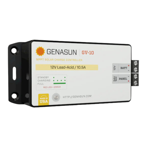
The GV-10 can be mounted in any orientation.
Do not expose to water.
Do not mount in direct sunlight or near a source of heat.
Allow adequate airflow around the controller to achieve maximum output capability.
For outdoor use, the controller must be housed in an enclosure providing protection
at least equivalent to NEMA Type 3.
SELECTING THE BATTERY TYPE (LEAD-ACID / PB MODEL ONLY)
Your GV-10-Pb-12V controller is supplied set to the “SEALED” charging profile, which is appropriate for most
types of sealed lead-acid and gel batteries, as well as some types of AGM batteries. A “FLOODED” setting is
available for flooded batteries and other types of AGM batteries. The “FLOODED” setting includes equalization
charging. Please consult the specification table at the end of this manual to determine the best setting for
your battery type. To change your GV-10 controller to the “FLOODED” setting, unscrew the four screws on the
diagram 1. Use care when installing the jumper, as incorrect installation can damage the controller. For sealed
batteries, do not install the jumper.
r
e
CONNECTING THE SOLAR PANEL
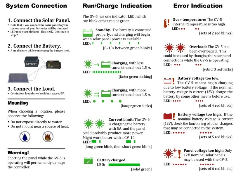
Connect the solar panel to the +PANEL and –PANEL terminals. While connecting the battery first
will not damage the GV-10, we recommend connecting the panel first. This eliminates the risk of short-
circuiting the panel while the GV-10 is operating, which can cause damage.
In most applications, the panel should be connected only to the GV-10.
Do not use blocking diodes for single panel installations; they reduce system
performance with no benefit.
Multiple panels may be connected in parallel up to the maximum power limit of the controller, with
a blocking diode used for each panel (unless otherwise recommended by the panel manufacturer).
These panels should be the same model and facing the same direction, otherwise we recommend
using a separate controller for each panel.
Solar panel voltage rises in cold weather. Check that the solar panel open circuit voltage (Voc)
will remain below the maximum input voltage of the GV-10 at the coldest possible expected
temperature.
Note: In the GV-10, the negative side of the battery is connected internally to the negative side of the
solar panel.
(NFPA 70) or the standards in force at the installation location.
Electrical connections may be made in any order; however the sequence below is
recommended.
CONNECTING THE BATTERY
Connect the battery to the +BATT and –BATT terminals.
A small spark while connecting the battery is ok.
Any loads should be connected directly to the battery. The GV-10 does not provide
protection against over-discharge.
t
u
Note: Make sure to inspect the controller at least once
per year to ensure proper performance. Please see the
Inspection & Maintenance section in this guide.
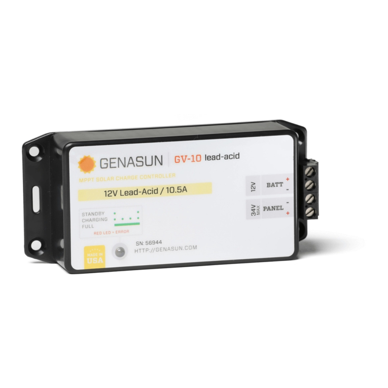
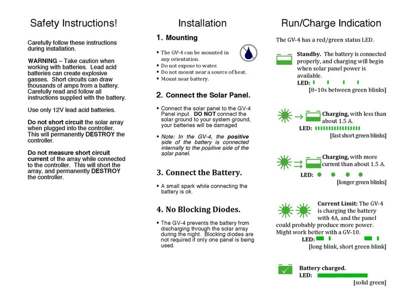
The GV-10 has a
MULTICOLOR LED.
Learn about this indicator
on the following page.
