Blue Sea Systems WeatherDeck 4302 User manual
CAUTION symbol refers to a potentially hazardous situation which, if not avoided, may
result in minor or moderate injury.
WARNING symbol refers to a potentially hazardous situation which, if not avoided, could
result in death or serious injury.
Instructions
WeatherDeck®Waterproof Fuse Panels
PN 4302 / PN 4304 / PN 4306 / PN 4308
Blue Sea Systems Inc. p 360.738.8230
425 Sequoia Drive f 360.734.4195
www.bluesea.com
6443 Rev.005
WARNING
CAUTION
Installation
GUARANTEE: Blue Sea Systems stands behind its products for as long
as you own them. Find detailed information at www.bluesea.com/about.
For customer service, call 800-222-7617.
Maximum Operating Voltage 12V DC
Maximum Operating Amperage 15A @ 12V DC (per circuit)
Backlight Operating Current (Amperage) 10mA/Illuminated Circuit
Panel Cumulative Rating 30A (PN 4302)
60A (PN 4304)
90A (PN 4306)
100A (PN 4308)
Switch Rating 15A Maximum
Backlighting Voltage 12V DC Nominal
Fuse Rating 15A installed, others available
Material: Cover UV Resistant Thermoplastic
Panel UL-V0 Flame Resistant Thermoplastic
Regulatory
Waterproof IP67—Protected against immersion up to 1 meter for 30 minutes
Specications
Specications subject to change. See bluesea.com for additional information and specications
Designed for open-cockpit and ybridge applications
• Includes 15A, ATO®/ATC®Fuse installed in each position
• Bicolored LEDs illuminate circuit labels to quickly identify OFF (Red),
ON (Green), or Blown (No color) circuits
• Backlighting is compatible with DeckHand Dimmers
• Independent label backlighting allows switching and dimming
• Integrated switch guards reduce the risk of accidental switching
• Panels can be mounted in four different orientations
• Panel front rated waterproof IP67 when properly mounted with the
watertight mounting gasket
• UV stabilized weather-resistant faceplate snaps on and off providing
access to components and concealing mounting screws
• Square Format Label Set 4215 included
DC AC
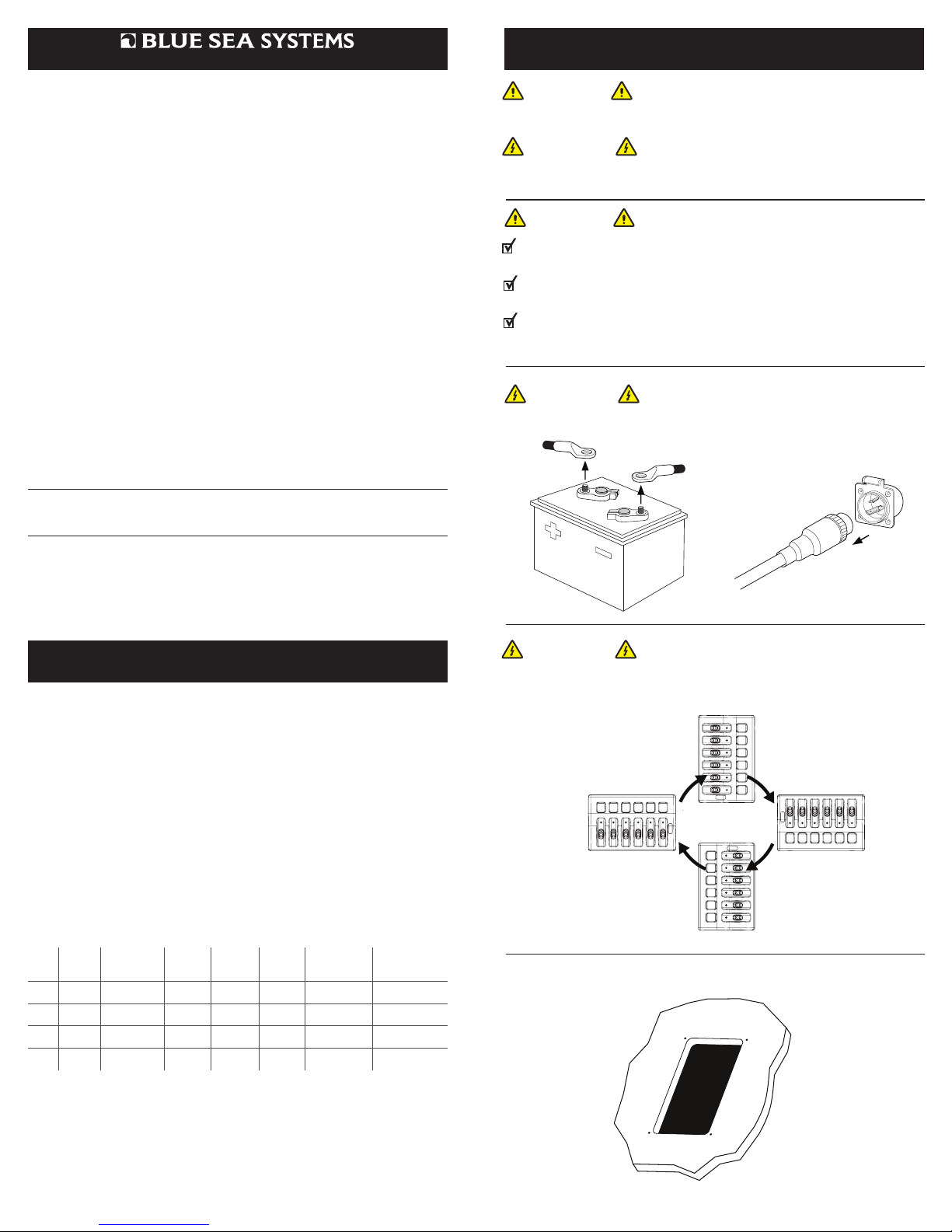
1. Before beginning electrical installation, disconnect all AC and DC power sources.
2. Selectmountinglocationandpanelorientationawayfromammableareas.
Panel can be mounted in any of the four orientations shown below.
WARNING
CAUTION
If you are not knowledgeable about electrical systems, consult an
electrical professional.
If the panel front is to be exposed to water, it must be properly sealed to the surface.
The included gasket must be in place and the panel screwed down securely.
Panel switches are not ignition proof—the panel must NOT be installed in an
explosive environment such as a gasoline engine room or battery compartment.
3. Cut opening with template provided.
WARNING
PN
Positions Voltage Width
in (mm)
Height
in (mm)
Depth
in (mm)
Width
Mounting
Centers in (mm)
Height
Mounting
Centers in (mm)
4302 2 12V DC 3.88
(98.55)
2.60
(66.04)
2.50
(63.50)
3.31
(84.07)
2.04
(51.82)
4304 4 12V DC 3.88
(98.55)
4.30
(109.22)
2.50
(63.50)
3.31
(84.07)
3.74
(95.00)
4306 6 12V DC 3.88
(98.55)
6.00
(152.40)
2.50
(63.50)
3.31
(84.07)
5.44
(138.18)
4308 8 12V DC 3.88
(98.55)
7.70
(195.58)
2.50
(63.50)
3.31
(84.07)
7.14
(181.36)
®

Installation (continued)
Apply 12V DC label, and circuit labels. Remove fuse seal and check that
appropriately rated fuses are installed for each device.
6. Make connections as per diagram at right.
a. Connect + 12V DC source to the busbar.
b. Connect -12V DC negative to quick connect terminal
marked “Negative”.
c. Connect the positive side of each appliance to a switch
output terminal. Connect the negative side to DC negative.
4. To remove cover, apply heal of hand to label area and pull back on the cover edge.
Application Example
Connect adequate gauge supply
wire and circuit protection for
safe operation up to Panel
Cumulative Rating.
PN 4306 shown for
illustration purposes
VHF
BILGE PUMP
FISH FINDER
STEREO
HORN
GPS
EXAMPLE DEVICES
COMMON BUSBAR
FUSE
Legend
DC Positive
DC Negative
Optional: For dimming control of
label backlighting, remove
dimmer control wire from busbar
and connect to an electronic
Pulse Width Modulating dimmer
like Blue Sea Systems PN 7506.
CAUTION! If 24-hour bilge
function is required, constant
power source must be considered.
Optional:ON-OFF Battery Switch
like Blue Sea Systems’ PN 6006 or
9003e.
5. Securely tighten toggle switch boots. Mount panel in cutout with provided
gaskets and screws. Insert fuse seal over fuses, ensure 2 seal ribs are
pressed in the panel. Reattach the cover.
COVER FUSE SEAL FUSES
CIRCUIT LABELS
GASKET
VOLTAGE LABEL
COVER
FUSE SEAL
TOGGLE
SWITCH
BOOTS
CUTOUT
WITH GASKET
AND SCREWS
This manual suits for next models
3
Other Blue Sea Systems Control Panel manuals


Popular Control Panel manuals by other brands

Schenck process
Schenck process Intecont Tersus Beltweigher instruction manual

Ravel
Ravel RE-900 Installation, commissioning & operating user manual

HST
HST HST-HP201-2AB product manual

Agilent Technologies
Agilent Technologies Turbo-V 69-8850 user manual

AERMEC
AERMEC FMT 10 Use and installation manual

NAPCO
NAPCO Gemini GEM-P9600 Programming instructions


Bosch
Bosch D7212GV3 Program entry guide

DSC
DSC CLASSIC PC1555 instruction manual

Cozzia
Cozzia 16027 manual

Baumuller
Baumuller b maXX 3000 Instruction handbook

Comtech EF Data
Comtech EF Data RAP-100 Installation and operation manual

Channel Safety Systems
Channel Safety Systems FW1001 User manual & log book