2
Installation
6
Amendment 6
© Moffat Ltd, August 2015
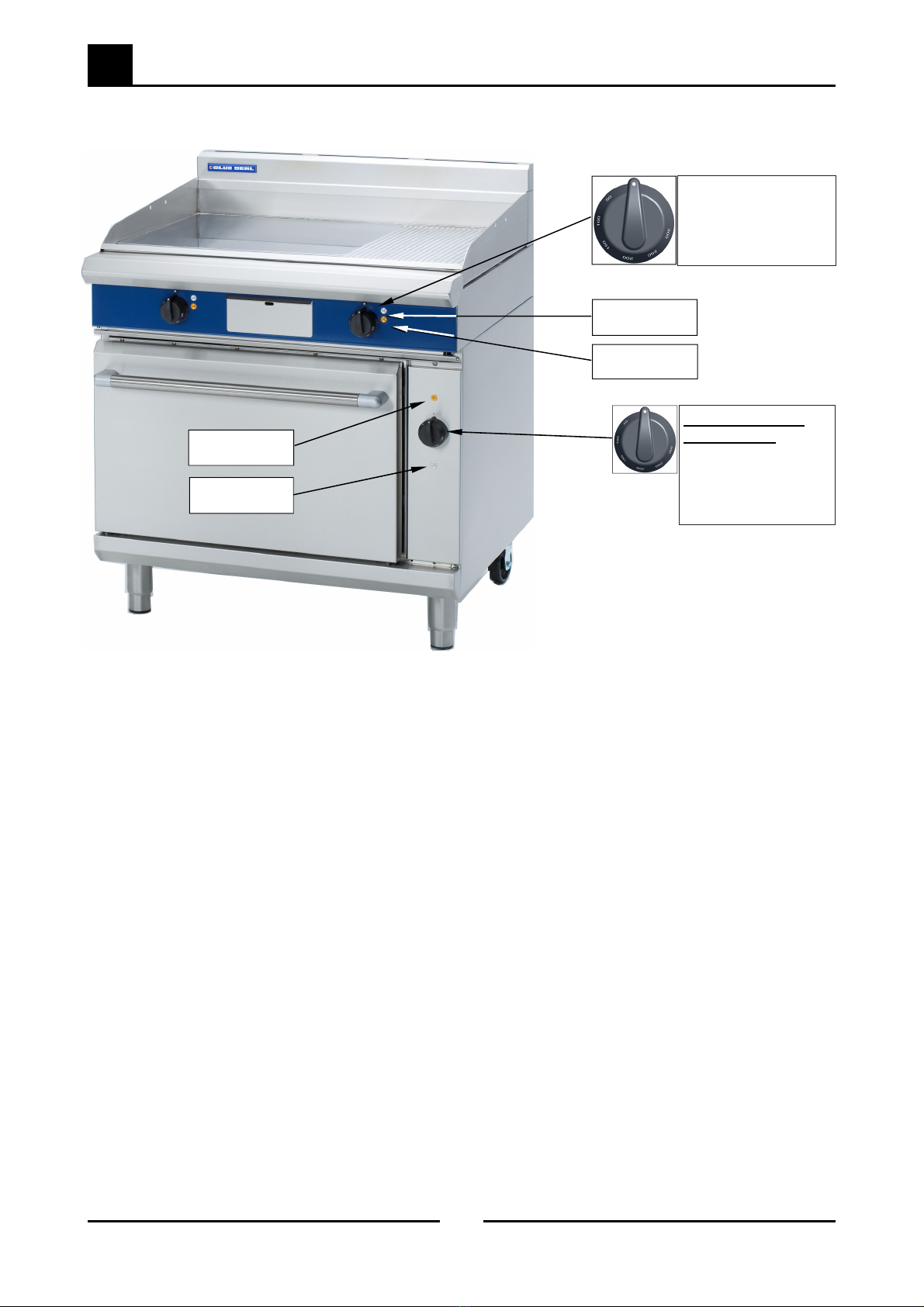
Blue Seal Evolution Series Electric Dedicated Griddle Ranges
Assembly
All Models
All models come pre-assembled.
NOTE: This appliance is fitted with adjustable feet / castors to enable the unit to be positioned securely and level. This
should be carried out on completion of electrical connection. Refer to the 'Electrical Connection' section.
Optional Accessories (Refer to Replacement Parts List)
Plinth Kit. For installation details, refer to the instructions supplied with each kit.
Electrical Connection
Each appliance should be connected to an adequately protected power supply and isolation switch mounted adjacent to, but not
behind the appliance. This switch must be clearly marked and readily accessible in case of fire.
1. Check that the electricity supply is correct as shown on the Rating Plate.
(Refer to the dimension drawings for rating plate location).
2. The supply terminal connections are located at the rear of the the appliance.
Refer to ‘Electrical Connections’ in the ‘Specifications’ section of the manual.
3. Remove the control panel to allow connection access for the electrical supply.
4. Bring the supply cable up through the grommet at the back of the appliance
and through the compression type gland provided on the rear of the main
electrical switchgear panel.
5. Connect the mains supply to L1, L2 and L3 fuse carrier connections for 3
phase.
6. Connect neutral and earth conductors to neutral stud and earth stud
respectively.
7. For all connections ensure that conductors are secure and appropriately
terminated.
8. Tighten the cable gland to secure against tension on the cable.
NOTE:
This appliance must be grounded / earthed.
Fixed wiring installations must incorporate an all-pole disconnection switch.
9. Correctly locate the appliance into its final operating position and using a spirit level, adjust the legs so that the appliance is level
and at the correct height.
10. Connect the power supply to the appliance.
11. Check that the electrical supply is as shown in the 'Specifications' section.
Commissioning
1. Before leaving the new installation;
a. Check the following functions in accordance with the operating instructions.
Check the current draw and loading for the equipment. Refer to the 'Specification' section for the correct electrical
requirements.
Check that all the connections are correct and that all cover panels have been re-fitted.
Check that the appliance functions in accordance with the operating instructions.
Ensure that this instruction manual is left with the appliance.
b. Ensure that the operator has been instructed in the areas of correct operation and shutdown procedure for the appliance.
NOTE:
If for some reason it is not possible to get the appliance to operate correctly, turn off the electrical power
supply and contact a qualified service person. The supplier of this appliance will be able to recommend a
suitable person.
Make sure that the electrical supply is turned off before any service or maintenance work is carried out.
Rating Plate
Location
THIS APPLIANCE MUST BE EARTHED. IFTHE SUPPLY CORD IS DAMAGED, IT MUST BE REPLACED BY ASUITABLY QUALIFIED PERSON IN
ORDER TO AVOID AHAZARD.
Warning