Installation
3
© Moffat Ltd, January 2007
Revision 1/
Blue Seal Evolution Series Gas Salamander
Installation Requirements
NOTE: It is most important that this salamander is installed correctly and that operation is
correct before use. Installation shall comply with local electrical, gas, health and
safety requirements.
Blue Seal Salamanders are designed to provide years of satisfa tory servi e, and orre t installation is
essential to a hieve the best performan e, effi ien y and trouble-free operation.
This applian e must be installed in a ordan e with National installation odes and in addition, in
a ordan e with relevant National / Lo al odes overing gas and fire safety.
AUSTRALIA: - AS5601 - Gas Installations.
NEW ZEALAND: - NZS5261 - Gas Installation.
UNITED KINGDOM: - Gas Safety (Installation & Use) Regulations 1998.
- BS6173 - Installation of Catering Applian es.
- BS5440 - 1 & 2 Installation Flueing & Ventilation.
IRELAND: - IS 820 - Non - Domesti Gas Installations.
Installations must be carried out by qualified service persons only. Failure to install
equipment to the relevant codes and manufacturer’s specifications shown in this section will
void the warranty.
Components having adjustments protected (e.g. paint sealed) by the manufacturer are only
allowed to be adjusted by an qualified service person. They are not to be adjusted by the
installation person.
Unpacking
• Remove all pa kaging and transit prote tion from the applian e in luding all prote tive plasti
oating from the exterior stainless steel panels.
• Che k equipment and parts for damage. Report any damage immediately to the arrier and
distributor.
• Report any defi ien ies to the distributor who supplied the applian e.
• Che k that the available gas supply is orre t to that shown on the rating plate lo ated on the front
bottom orner of the right hand side panel.
• Che k that the following parts have been supplied with the applian e:
Location
1. Installation must allow for a suffi ient flow of fresh air for the ombustion air supply.
Combustion Air Requirements
Natural Gas 9m³/hr minimum.
LPG / Propane 9m³/hr minimum.
2. Installation must in lude adequate ventilation means, to prevent dangerous build up of ombustion
produ ts.
1 x Salamander Ra k. 1 x Wall Mounting Bra ket, in luding;
1 x Trough Tray. - 2 x 25mm Bla k Plasti Spa ers.
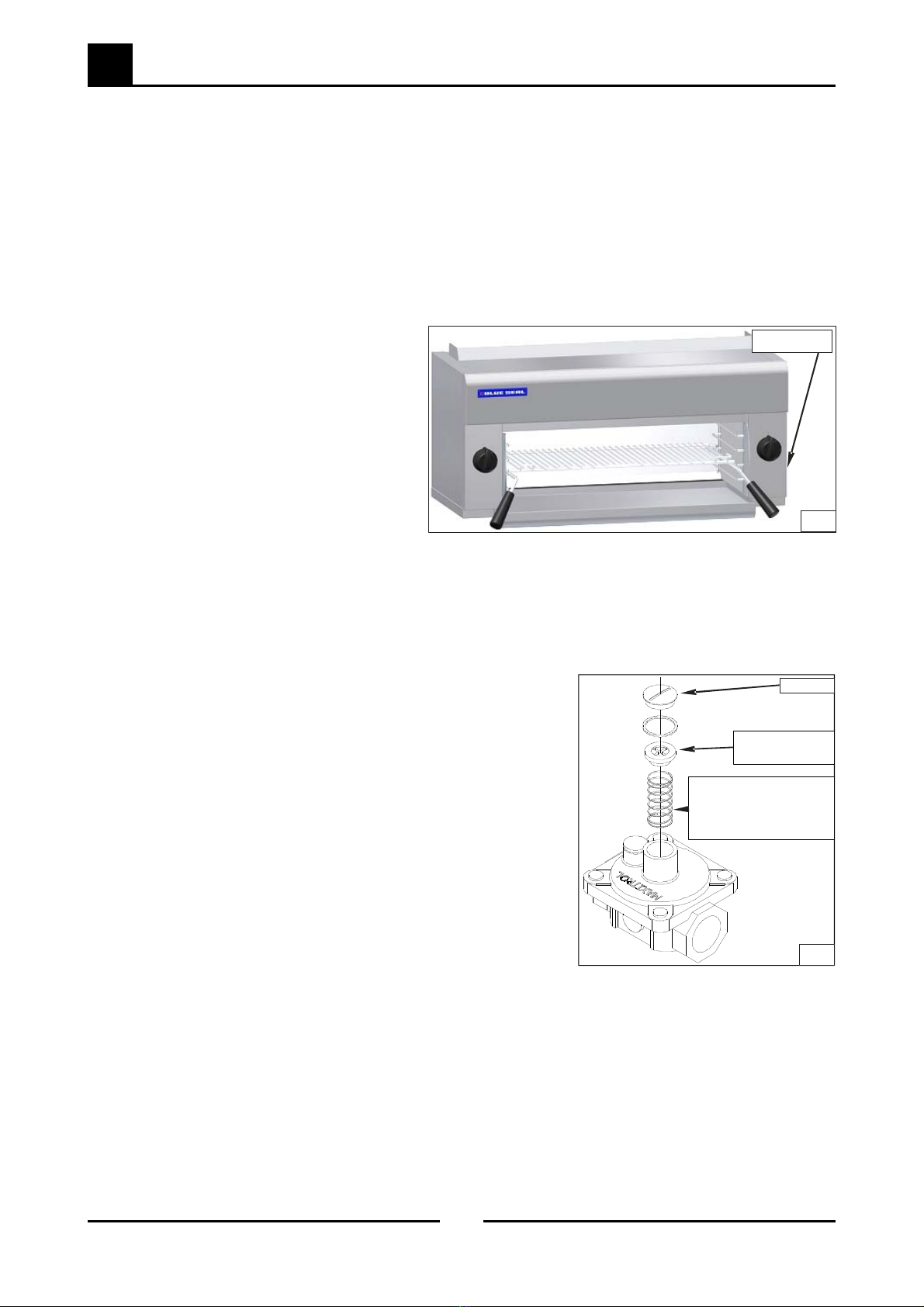
1 x Gas Regulator. - 2 x 3/8” Bolts / Nuts.
1 x Alternate Gas Conversion Kit.