Blue Technix EVAL-BF5 Series Instructions for use
www.tinyboards.com
Maximum Power at Minimum Size
Hardware User Manual
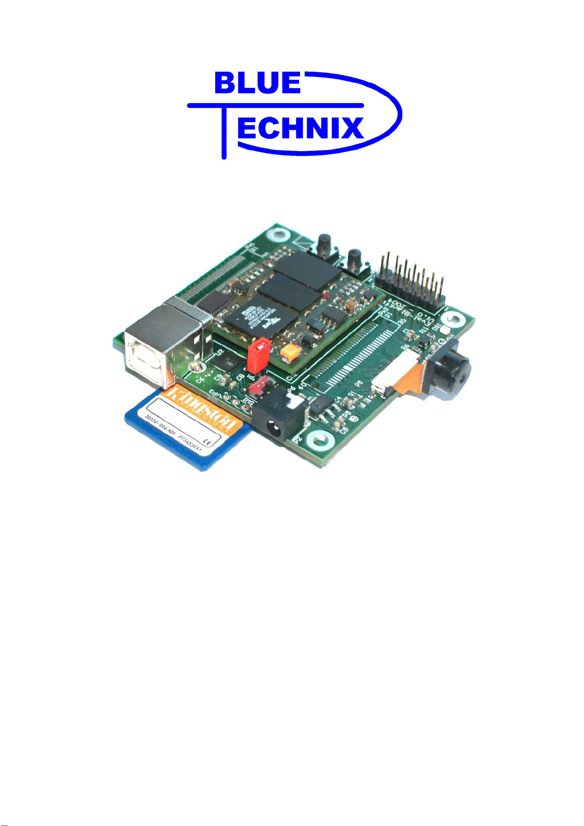
EVAL-BF5xx Board
* SD-Card and Camera Module are not included in the EVAL-BF5xx package.

Blackfin EVAL-BF5xx Hardware User Manual
Contact
Bluetechnix Mechatronische Systeme GmbH
Waidhausenstr. 3/19
A-1140 Vienna
AUSTRIA/EUROPE
http://www.bluetechnix.com
http://www.tinyboards.com
Version 2.0
2005-05-31
Document No.: 100-2022-01

Blackfin EVAL-BF5xx Hardware User Manual
Table of Contents
1 Introduction ......................................................................................................................... 1
1.1 Overview....................................................................................................................... 1
1.2 Related Products ........................................................................................................... 2
2 Specification........................................................................................................................ 3
2.1 Functional Specification ............................................................................................... 3
2.2 Connectors, PCB Placement and PIN Assignment....................................................... 4
2.2.1 P1 – USB Connector.............................................................................................. 4
2.2.2 P2 – Power Connector............................................................................................ 4
2.2.3 Px1 – Expansion Connector 1................................................................................ 5
2.2.4 Px2 – Expansion Connector 2................................................................................ 6
2.2.5 P5 – Expansion OmniVision Camera Connector................................................... 6
2.2.6 P6 – JTAG Connector............................................................................................ 7
2.2.7 SW1 – UART Switch............................................................................................. 7
2.2.8 JP1 - Power Supply Jumper ................................................................................... 7
2.2.9 JP3 – UART Solder Pads....................................................................................... 7
2.2.10 Buttons and LED................................................................................................. 7
2.3 Mechanical Outline....................................................................................................... 8
3 Known Bugs........................................................................................................................ 9
4 Revision History................................................................................................................ 10
A List of Figures and Tables.............................................................................................. 11

Blackfin EVAL-BF5xx Hardware User Manual
Edition 2005-02
© Bluetechnix Mechatronische Systeme GmbH 2005
All Rights Reserved.
The information herein is given to describe certain components and shall not be considered as
a guarantee of characteristics.
Terms of delivery and rights of technical change reserved.
We hereby disclaim any warranties, including but not limited to warranties of non-
infringement, regarding circuits, descriptions and charts stated herein.
Bluetechnix makes and you receive no warranties or conditions, express, implied, statutory or
in any communication with you. Bluetechnix specifically disclaims any implied warranty of
merchantability or fitness for a particular purpose.
Bluetechnix takes no liability for any damages and errors causing of the usage of this board.
The user of this board is responsible by himself for the functionality of his application. He is
allowed to use the board only if he has the qualification. More information is found in the
General Terms and Conditions (AGB).
Information
For further information on technology, delivery terms and conditions and prices please
contact Bluetechnix (http://www.bluetechnix.at).
Warnings
Due to technical requirements components may contain dangerous substances.
The Core Boards and Development
systems contain ESD (electrostatic
discharge) sensitive devices. Electro-
static charges readily accumulate on
the human body and equipment and
can discharge without detection.
Permanent damage may occur on
devices subjected to high-energy
discharges. Proper ESD precautions
are recommended to avoid
performance degradation or loss of
functionality. Unused core boards
and development boards should be
stored in the protective shipping
package.

Bluetechnix www.tinyboards.com
Maximum Power at Minimum Size
Blackfin EVAL-BF5xx Hardware User Manual Page 1
1 Introduction
The EVAL-BF5xx Board is a very low cost and lightweight evaluation platform for
Bluetechnix core modules CM-BF533 and CM-BF561. The small baseboard has all hardware
necessary to test the performance of the core modules including a high-speed serial port
directly connectable to a computers USB port, a digital video camera interface and a SD-Card
mass storage device socket.
1.1 Overview
The EVAL-BF5xx Board includes the following components:
60 Pin Expansion Connector A
USB CM-BF533
or
CM-F561
Coremodule SD-Card
Connector
60 Pin Expansion Connector B
Camera
Connector
JTAG
Figure 1-1: Overview of the EVAL-BF5xx Board
1 Coremodule Slot
oSupports the CM-BF533 as well as the CM-BF533 core modules
Camera Connector
oSupports the ITU-656 OmniVision Camera OV7648 available in the camera
kit.
oCamera drivers are supplemented in the camera kit.
USB
oSupports up to 915kbps UART-USB conversion.
oEmulates a standard COM port on the computer.
JTAG
oJTAG-Plug that supports all analog Devices JTAG Emulators.

Bluetechnix www.tinyboards.com
Maximum Power at Minimum Size
Blackfin EVAL-BF5xx Hardware User Manual Page 2
Expansion Connector 1
oSPORT 0
oJTAG
oUART
oSPI
oPPI-1 (Parallel Port Interface 1)
oPFs (Programmable Flags)
Expansion Connector 2
oData Bus
oAddress Bus
oMemory Control Signals
oPPI-21(Parallel Port Interface 2)
oPower Supply
The Camera Module as well as the SD-Card as shown on the cover page are not
included in the EVAL-BF5xx Board.
For the Camera Module the Kit-CAM-OV1 can be purchased from Bluetechnix.
1.2 Related Products
CM-BF533: Blackfin DSP Processor Module powered by Analog Devices single core
BF533 processor. Up to 600MHz, 32MB RAM, 2MB Flash, 36x31mm, 120
pin expansion connector, BGA option.
CM-BF561: Blackfin DSP Processor Module powered by Analog Devices new dual core
BF561 processor. Up to 2x 600MHz, 32MB RAM, 4MB Flash, 36x31mm,
120 pin expansion connector, BGA option.
DEV-Blackfin: Blackfin DSP Development board with two sockets for any combination of
CM-BF533 and CM-BF561 core modules. Additional periphery is available,
such as CF-Card, SD-Card, DP-Ram, Ethernet, USB host and device, multi-
port JTAG and 2 connectors for a digital stereo camera system.
Kit-CAM-OV1: Camera Kit including one OmniVision OV7648 camera for the Blackfin
core boards and the respective software driver
1Only available when using the CMBF561 Coremodule

Bluetechnix www.tinyboards.com
Maximum Power at Minimum Size
Blackfin EVAL-BF5xx Hardware User Manual Page 3
2 Specification
2.1 Functional Specification
Button
LED
Reset
2V5 Voltage
Regulator
3V3
Regulator
USB/UART
Switch
60-pin : Data & Addr. Us, Mem. Control, (PPI2)
60-pin : JTAG, PPI-1, SPORT0, (SPORT1),UART, SPI, PFs
CM-BF533
or
CM-F561
Coremodule
JTAG
Connector
USB-UART
Converter
USB Device
Connector
UART
Expansion
OmniVision
Camera
Connector
SD-Card
Connector
PPI1
SPI
Optional
Power
Connector
UART
JTAG
Figure 2-1: Detailed Block Diagram
Figure 2-1 shows a detailed block diagram of the EVAL-BF5xx Board.
From the Power connector or the USB Device connector power connects to a 1 Ampere linear
voltage regulator that powers the coremodule.
The serial port of the coremodule can be routed directly to the USB Port (USB/UART Switch
Position A towards the board edge) or to the UART Expansion Pads (USB/UART Switch
Position B towards the coremodule).
The two 60-pin expansion connectors bring al pins of the Coremodule (Section 2.2.3 and
2.2.4) directly on the expansion slot.
An SD-Card connector mounted at the bottom of the board allows making use of file IO
Functions delivered with the Blacksheep Software. Blacksheep supports SD-Cards up to 512
MB and includes a FAT16 files systems as well as the most relevant File IO Functions.
Adding a Camera Kit to the EVAL-BF5xx Board allows connecting directly a high
performance OmniVision Camera to the board via the OmniVision Camera connector.
Blacksheep Software fully supports drivers for the Camera Module.

Bluetechnix www.tinyboards.com
Maximum Power at Minimum Size
Blackfin EVAL-BF5xx Hardware User Manual Page 4
2.2 Connectors, PCB Placement and PIN Assignment
Figure 2-2: Connector PCB Placement
2.2.1 P1 – USB Connector
P1 is a standard USB-B Device Connector from which the board may draw its power of up to
500mA at most. Without extension board this is enough power to run a CM-BF561 board @
600MHz including a SD-Card and the OmniVision Camera.
2.2.2 P2 – Power Connector
As a second power supply option, or if the 500mA provided by USB are not sufficient, P2 can
be used as the main or as the secondary power connector. Both connectors P1 and P2 can be
plugged into the evaluation board at the same time.

Bluetechnix www.tinyboards.com
Maximum Power at Minimum Size
Blackfin EVAL-BF5xx Hardware User Manual Page 5
P2
PIN
Number Signal Description
1 GND
2 NC
3 +4V to +7V Input Supply Preferable 5V
2.2.3 Px1 – Expansion Connector 1
Pin 1 through Pin 60 of Px1 is connected directly to Pin 61 through Pin 120 of any
Coremodule (CM).
Part Baseboard Manufacturer Manufacturer ID
Px1,Px2 AMP 177983-2 (female) or 177984-2 (male)
Table 2-1: Connector Px1 pin assignment
PIN PIN
Px1 CM Signal Signal
type PIN PIN
Px1 CM Signal Signal
type
1 -> 61 ABE3 O 2 -> 62 A3 O
3 -> 63 A5 O 4 -> 64 A7 O
5 -> 65 A9 O 6 -> 66 A11 O
7 -> 67 A13 O 8 -> 68 A15 O
9 -> 69 PPI2C1 O 10 -> 70 PPI2C2 O
11 -> 71 PPI2D1 O 12 -> 72 PPI2D3 -
13 -> 73 PPI2D5 - 14 -> 74 PPI2D7 -
15 -> 75 PPI2D9 - 16 -> 76 PPI2D11 I
17 -> 77 PPI2D13 O 18 -> 78 PPI2D15 O
19 -> 79 GND PWR 20 -> 80 /AMS1 O
21 -> 81 /AWE O 22 -> 82 NMI I
23 -> 83 D0 I/O 24 -> 84 D2 I/O
25 -> 85 D4 I/O 26 -> 86 D6 I/O
27 -> 87 D8 I/O 28 -> 88 D10 I/O
29 -> 89 D12 I/O 30 -> 90 D14 I/O
31 -> 91 D15 I/O 32 -> 92 D13 I/O
33 -> 93 D11 I/O 34 -> 94 D9 I/O
35 -> 95 D7 I/O 36 -> 96 D5 I/O
37 -> 97 D3 I/O 38 -> 98 D1 I/O
39 -> 99 /Reset I 40 -> 100 /AOE O
41 -> 101 /ARE O 42 -> 102 /AMS2 O
43 -> 103 3V3 PWR 44 -> 104 PPI2D14 I/O
45 -> 105 PPI2D12 I/O 46 -> 106 PPI2D10 I/O
47 -> 107 PPI2D8 I/O 48 -> 108 PPI2D6 I/O
49 -> 109 PPI2D4 I/O 50 -> 110 PPI2D2 I/O
51 -> 111 PPI2D0 I/O 52 -> 112 PPI2C3 I/O
53 -> 113 PPI2C0 I/O 54 -> 114 A14 O
55 -> 115 A12 O 56 -> 116 A10 O
57 -> 117 A8 O 58 -> 118 A6 O
59 -> 119 A4 O 60 -> 120 A2 O

Bluetechnix www.tinyboards.com
Maximum Power at Minimum Size
Blackfin EVAL-BF5xx Hardware User Manual Page 6
2.2.4 Px2 – Expansion Connector 2
Pin 1 through Pin 60 of Px2 is connected directly to Pin 1 through Pin 60 of any Coremodule.
Part Baseboard Manufacturer Manufacturer ID
Px1,Px2 AMP 177983-2 (female) or 177984-2 (male)
PIN PIN
Px1 = CM Signal Signal
type PIN PIN
Px1 = CM Signal Signal
type
1 RSCLK0 I/O 2 DR0PRI I
3 TSCLK0 I/O 4 DT0PRI O
5 PF11 (Clk_out) I/O 6 PF9 I/O
7 PF7 I/O 8 PF5 I/O
9 Vin 3V3 PWR 10 Vin 3V3 PWR
11 PPI1D0 I/O 12 PPI1D2 I/O
13 PPI1D4 I/O 14 PPI1D6 I/O
15 PPI1D8 I/O 16 PPI1D10 I/O
17 PPI1D12 I/O 18 PPI1D14 I/O
19 PPI1SY3/PF3 I/O 20 PPI1SY1 / TMR1 I/O
21 PF3 I/O 22 PF1 I/O
23 RX I 24 MOSI I/O
25 SCK I 26 ABE2 O
27 ARDY I 28 TCK I
29 TDI I 30 TRST I
31 EMU I 32 TMS O
33 TDO O 34 AMS3 O
35 ABE1 O 36 ABE0 O
37 MISO I/O 38 TX O
39 PF0 I/O 40 PF2 I/O
41 PPI1CLK I/O 42 PPI1SY2 / TMR2 I/O
43 PPI1D15 I/O 44 PPI1D13 I/O
45 PPI1D11 I/O 46 PPI1D9 I/O
47 PPI1D7 I/O 48 PPI1D5 I/O
49 PPI1D3 I/O 50 PPI1D1 I/O
51 GND PWR 52 GND PWR
53 PF4 I/O 54 PF6 I/O
55 PF8 I/O 56 PF10 I/O
57 DT0SEC O 58 TFS0 I/O
59 DR0SEC I 60 RFS0 I/O
Table 2-2: Connector Px2 pin assignment
GREY Shaded Connector PINS indicate difference to CM-BF533
2.2.5 P5 – Expansion OmniVision Camera Connector
PIN Signal Signal
type PIN PIN
Px1 = CM Signal Signal
type

Bluetechnix www.tinyboards.com
Maximum Power at Minimum Size
Blackfin EVAL-BF5xx Hardware User Manual Page 7
1 GND I/O 2 HREF (NC) I
3 VSYNC (NC) I/O 4 PWDN (PPID10) O
5 PCLK (PPICLK) I 6 2V5 VDD I/O
7 3V3 DOVDD PWR 8 SIO_D (PPID9) I/O
9 CamClk (*) I 10 SIO_C (PPID8) I
11 D0 O 12 D1 O
13 D2 O 14 D3 O
15 GND O 16 D4 O
17 D5 O 18 D6 O
19 D7 O 20 Reset (GND) I
(*) Mount option R1/R5: Mount R1 for CM-BF533 clock source ; Mount R5 for CM-
BF561 clock source
2.2.6 P6 – JTAG Connector
The JTAG connector is compliant to any Blackfin JTAG Emulator from Analog Devices.
2.2.7 SW1 – UART Switch
Move Sw1 to POSITION A to route the Coremodules RX and TX signals to USB
Move Sw1 to Position B to route the Coremodules RX and TX signals to JP3
2.2.8 JP1 - Power Supply Jumper
This jumper can be removed in order to insert an AMPERE METER for current measurement
of the entire Coremodule.
2.2.9 JP3 – UART Solder Pads
JP3
PIN Number Signal Description
1 TXD Blackfin Output Coremodule
2 RXD Blackfin Input Coremodule
3 GND
4 3V3 Regulated Power
2.2.10 Buttons and LED
The Button S1 is the main Reset Button of the Coremodule.
The Button S2 is a general purpose input button connected to the PF2 PIN of the CM-BF533
or to the PF3 PIN of the CM-BF561.
The LED is Connected to the PPID15 (PF3) pin of the CM-BF533 or to the PPID15 (PF47)
PIN of the CM-BF561
Bluetechnix www.tinyboards.com
Maximum Power at Minimum Size
Blackfin EVAL-BF5xx Hardware User Manual Page 8
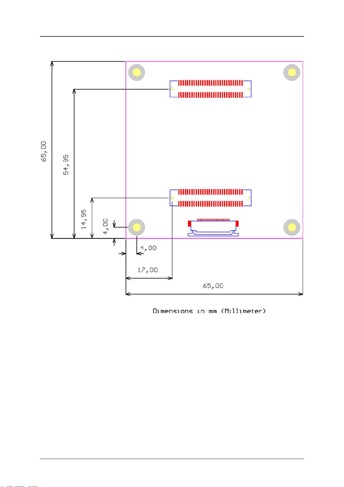
2.3 Mechanical Outline
Figure 2-3: Mechanical Outline – Expansion Connector Placement

Bluetechnix www.tinyboards.com
Maximum Power at Minimum Size
Blackfin EVAL-BF5xx Hardware User Manual Page 9
3 Known Bugs

Bluetechnix www.tinyboards.com
Maximum Power at Minimum Size
Blackfin EVAL-BF5xx Hardware User Manual Page 10
4 Revision History
2005-02-08 Release Version No. 1.0

Bluetechnix www.tinyboards.com
Maximum Power at Minimum Size
Blackfin EVAL-BF5xx Hardware User Manual Page 11
A List of Figures and Tables
Figure 1-1: Overview of the EVAL-BF5xx Board ....................................................................1
Figure 2-1: Detailed Block Diagram..........................................................................................3
Figure 2-2: Connector PCB Placement......................................................................................4
Figure 2-3: Mechanical Outline – Expansion Connector Placement.........................................8
Table 2-1: Connector Px1 pin assignment ................................................................................. 5
Table 2-2: Connector Px2 pin assignment ................................................................................. 6
Table of contents
Other Blue Technix Motherboard manuals


Popular Motherboard manuals by other brands


ASROCK
ASROCK X79 Extreme9 user manual

Intel
Intel DH61BE Product guide

National Semiconductor
National Semiconductor LMX2531LQ1700E operating instructions

Texas Instruments
Texas Instruments TLC5944EVM-358 user guide

Asus
Asus CROSSHAIR III FORMULA - Republic of Gamers Series... user guide

Biostar
Biostar TZ77A manual


