BlueBox IDTRONIC UHF Advant 5238U-PN-C User manual
BLUEBOX Advant Profinet Page 1 of 71
UHF
RFID System
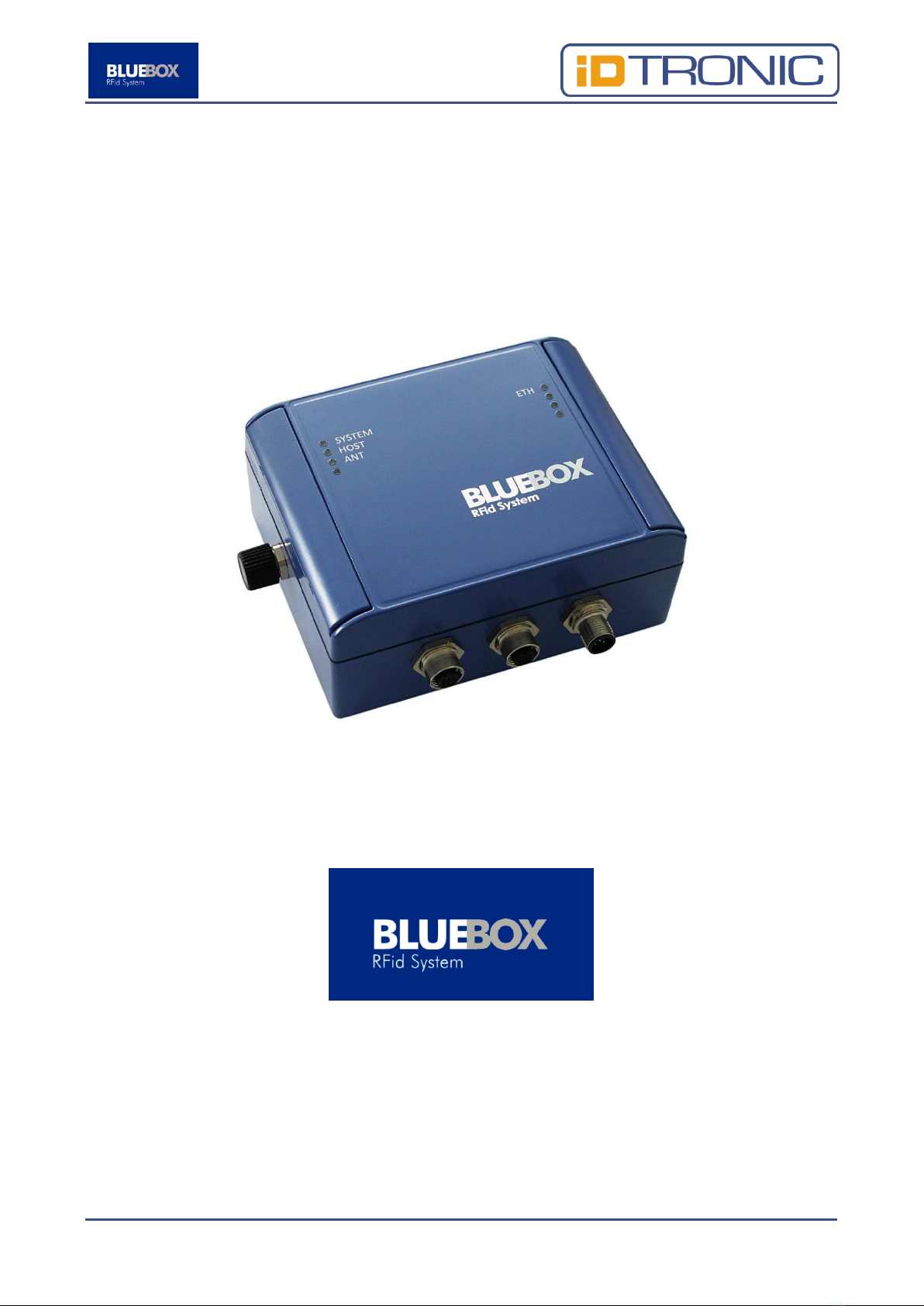
BLUEBOX Advant 5238U-PN-C
Profinet

BLUEBOX Advant Profinet Page 2 of 71
Preface
iDTRONIC GmbH (IDTRONIC) reserves the right to make changes to its products
or services or to discontinue any product or service at any time without notice.
IDTRONIC provides customer assistance in various technical areas, but does not
have full access to data concerning the use and applications of customer's
products. Therefore, IDTRONIC assumes no liability and is not responsible for
customer applications or product or software design or performance relating to
systems or applications incorporating IDTRONIC products. In addition,
IDTRONIC assumes no liability and is not responsible for infringement of patents
and/or any other intellectual or industrial property rights of third parties, which
may result from assistance provided by IDTRONIC. IDTRONIC products are not
designed, intended, authorized or warranted to be suitable for life support
applications or any other life critical applications that could involve potential risk
of death, personal injury or severe property or environmental damage. With the
edition of this document, all previous editions become void. Indications made in
this manual may be changed without previous notice. Composition of the
information in this manual has been done to the best of our knowledge.
IDTRONIC does not guarantee the correctness and completeness of the details
given in this manual and may not be held liable for damages ensuing from
incorrect or incomplete information. Since, despite all our efforts, errors may not
be completely avoided, we are always grateful for your useful tips. The
installation instructions given in this manual are based on advantageous
boundary conditions. IDTRONIC does not give any guarantee promise for perfect
function in cross environments. The companies or products mentioned in this
document might be brands or brand names of the different suppliers or their
subsidiaries in any country. This document may be downloaded onto a computer,
stored and duplicated as necessary to support the use of the related IDTRONIC
products. Any other type of duplication, circulation or storage on data carriers in
any manner not authorized by IDTRONIC represents a violation of the applicable
copyright laws and shall be prosecuted.

BLUEBOX Advant Profinet Page 3 of 71
Safety Instructions / Warning - Read before start-up!
•The device may only be used for the intended purpose designed by the
manufacturer. The operation manual should be conveniently kept available
at all times for each user.
•Unauthorized changes and the use of spare parts and additional devices
that have not been sold or recommended by the manufacturer may cause
fire, electric shocks or injuries. Such unauthorized measures shall exclude
any liability by the manufacturer.
•The liability-prescriptions of the manufacturer in the issue valid at the time
of purchase are valid for the device. The manufacturer shall not be held
legally responsible for inaccuracies, errors, or omissions in the manual or
automatically set parameters for a device or for an incorrect application of
a device.
•Repairs may be executed by the manufacturer only.
•Only qualified personnel should carry out installation, operation, and
maintenance procedures.
•Use of the device and its installation must be in accordance with national
legal requirements and local electrical codes.
•When working on devices the valid safety regulations must be observed.

BLUEBOX Advant Profinet Page 4 of 71
This manual applies to the following devices:
Description:
Order Number:
Read / write UHF RFID device with one external
antenna. ProfiNet communication interface.
5238U-PN-C
This manual is valid as of firmware version:
Order Number
Carrier
Front End
5238U-PN-C
3.05
1.29M
iDTRONIC GmbH
Donnersbergweg 1
67059 Ludwigshafen
Germany/Deutschland
Phone: +49 621 6690094-0
Fax: +49 621 6690094-9
Web: idtronic.de
Issue 1.00
–05. July 2017 –
Subject to alteration without prior notice.
© Copyright iDTRONIC GmbH 2017
Printed in Germany

BLUEBOX Advant Profinet Page 5 of 71
Table of Contents
1Introduction...................................................................................... 6
2Technical Specifications...................................................................... 7
2.1 Electrical Features........................................................................ 7
2.2 Mechanical Features ..................................................................... 7
2.3 Environmental Conditions.............................................................. 8
2.4 Reading Performance Tests ........................................................... 8
3Operating Features ............................................................................ 9
3.1 General Parameters.....................................................................10
3.2 Configuration Parameters.............................................................12
3.2.1 Ethernet..............................................................................12
3.2.2 ProfiNet ..............................................................................13
3.2.1 Input/Output .......................................................................14
3.2.2 RF and EPC C1G2 (Class-1 Generation-2)................................16
3.2.3 Dynamic Power Management .................................................27
3.3 Device Status .............................................................................28
4Connections .....................................................................................30
5Antennas.........................................................................................34
6Status Indications: LEDs and Buzzer ...................................................36
7Mechanical Drawings.........................................................................38
8Installation ......................................................................................39
9Document Revision History ................................................................40
A. Regions of Operation.........................................................................41
A.1. Operation in North America ..........................................................41
A.2. Operation in Europe ....................................................................41
B. ‘.inf’ File ..........................................................................................43
C. ‘.gsdml’ File .....................................................................................45
D. Driver Install on Windows 8 OS ..........................................................66

BLUEBOX Advant Profinet Page 6 of 71
1Introduction
The 5238U-PN-C hereinafter named BLUEBOX is a read/write RFID device for
industrial application that communicates with a ‘host’ system (typically a PC or
a PLC) through a ProfiNet connection. The BLUEBOX acts as a joint through a
set of commands between the host system and the RFID tag/s (or
transponder/s) present near the antenna/s. The same 'master/slave' protocol is
used for the communication between the host system (‘master’) and the
BLUEBOX (‘slave’), independently of the kind of connection (point to point,
multidrop net, Ethernet). An USB connection, working as Virtual COM, is also
available and used as service interface port to configure the functional
parameters and to update the firmware of the device, the ‘BLUEBOX Show’
software of the SDK is foreseen to explicate these operations. Furthermore the
BLUEBOX is able to handle 2 channels of digital I/O; each channel can be used
as output to drive a low side load or as input either driven by a ‘PNP’ output or
by a ‘clean’ contact. Warning, when the I/O is used as input, do not use it also
as output to avoid conflicts! The BLUEBOX is available with an external RF
antenna.

BLUEBOX Advant Profinet Page 7 of 71
2Technical Specifications
2.1 Electrical Features
Power Supply
24Vdc ± 10%
Power Ratings
15W @RFout=27dBm
Operating Frequency
840 MHz … 960 MHz, software configurable
RF Output Power
Max 500mW (27dBm), software configurable
1 dB step
RF Input Sensitivity
-51…-87dBm, software configurable 1 dB
step
Antenna
1 external
Antenna Connection
TNC female, 50 Ω
Reading Distance
8 mt1
Supported Transponders
ISO 18000-6C (EPC Class-1 Generation-2)
Communication Interface
ProfiNet
Service Interface
USB Virtual COM
Digital Inputs/Outputs
2 optoisolated I/O, Voltage 24Vdc
As input: max current 10mA
As output: max current 500mA
Status Display
8 LEDs, Buzzer
Connections
M12 connections (Power, I/O, ProfiNet, USB
interface)
2.2 Mechanical Features
Dimensions
110 x 140 x 62 mm
Material
PC
Protection Class
IP67
1
Reading distance depends on transponder type, antenna and environmental conditions.

BLUEBOX Advant Profinet Page 8 of 71
2.3 Environmental Conditions
Operating Temperature
-20°C … +55°C
Storage Temperature
-40°C … +85°C
Humidity
Up to 95%, non condensing
2.4 Reading Performance Tests
The table below shows the minimum RF channel allocation time with different
inventory modes with no tags and with 1 tag in front of the antenna. The test
has been made using with a 4dBi gain circular antenna with output power of
27dBm and a tag at a distance of 0.5mt from the antenna.
Inventory Mode
Time with No Tag
Time with 1 Tag
Fast Multi Tag
15ms
23ms
Fast Single Tag
15ms
18ms
Standard Multi Tag
15ms
25ms
Standard Single Tag
15ms
20ms

BLUEBOX Advant Profinet Page 9 of 71
3Operating Features
In ‘continuous’ mode the BLUEBOX is characterized by the coexistence of 2
‘parallel’ and asynchronous activities: the tag identification (inventory) and the
communication with the ‘host’ system. The ‘continuous’ identification activity
interacts with the communication activity through a buffer that contains the code
of the last identified tags or that is empty indicating the absence of tags. Due to
synchronization and filtering reasons, the buffer is handled for each identified
tag by a parameter defined as ‘hold time’ (same as ‘filter time’ defined below,
to be set in the range of 0 … 99 seconds or 0 ... 99 minutes, default value 1
second) and allows to extend ‘artificially’ the presence of the tag after it leaves
the antenna’s influence area; this behavior is observable looking at the yellow
led status that is ‘on’ indicating the presence of tags and also through the
activation of the relay nr 1 (if its ‘automatic’ management is enabled by the flag
defined in the general parameters). Through the command ‘data request’ it is
possible to get the data contained in the buffer (tag/s ID/s and optionally tag/s
type/s, reading antenna and gate crossing direction in ‘gate mode’); the
indication of the reading antenna can be enabled/disabled through a flag defined
in the general parameters.
The BLUEBOX handles also a 1000 elements FIFO queue which is combined with
the ‘filter time’ general parameter (to be set in a range of 0 … 99 seconds or 0
... 99 minutes, default value 1 second) that prevents the queue saturation in
case of a tag ‘continuous’ presence. When a tag is identified, the BLUEBOX
verifies if it belongs to the list of read tags. If the tag do not belong to the list
(it is defined as ‘new’), its code will be inserted in the queue, a filter time
assigned to the tag will be started and the buzzer will be activated for 0.5
seconds (if its ‘automatic’ management is enabled by the flag defined in the
general parameters). Otherwise (the tag belong to the list of read tags), the
BLUEBOX verifies if the relative filter time is expired. In this case (the filter time
is expired), the tag is defined as ‘new’ and will be processed as described above,
otherwise only the relative filter time will be rearmed. Through the command
‘queue data request’ and the relative ‘ack’, it is possible to get the data contained
in the queue (tag ID and optionally tag type, reading antenna and gate crossing
direction in ‘gate mode’) and unload it; the indication of the reading antenna can
be enabled/disabled through a flag defined in the general parameters.
Two subsets of the ‘continuous’ mode are also defined:
•‘Trigger’ mode: the activation and deactivation of the ‘continuous’ mode is
triggered with inputs. The trigger could be level sensitive or edge sensitive
depending on the ‘extension time’ setting (to be set in a range of 0 … 99
seconds or 0 ... 99 minutes, default value 0 seconds).
•‘Gate’ mode: the activation of the ‘continuous’ mode is triggered with the
activation of an input. The deactivation of the ‘continuous’ mode is

BLUEBOX Advant Profinet Page 10 of 71
triggered with the activation of the other input but, the activation of the
‘continuous’ mode could also be extended with the ‘extension time’ (to be
set in a range of 0 … 99 seconds or 0 ... 99 minutes, default value 0
seconds). The crossing of the gate is managed with a maximum crossing
‘gate time’ (to be set in a range of 0 … 99 seconds or 0 ... 99 minutes,
default value 0 seconds) which deactivates the ‘continuous’ mode in case
of no successful crossing of the gate within this time. Only with a
successful crossing of the gate data (tag ID and gate crossing direction
and optionally tag type and reading antenna) are save in buffer and FIFO.
The BLUEBOX allows the execution of ‘on request’ functions. During the
execution of these functions, the ‘continuous’ identification activity will be
suspended temporarily; the involved commands are relative to device
configuration and tag read/write specific activities.
If not required, the ‘continuous’ identification activity can be disabled through a
flag defined in the general parameters. In this case, the BLUEBOX will only
execute the ‘on request’ commands already defined above.
Two ‘test’ mode are also defined:
•‘RF Reading’ test: in ‘continuous’ mode allows the user to easily and
quickly test the read range of the device with fast beeping (100ms) the
buzzer (the buzzer must be connected to output 2) for every identified
tag. This ‘test’ mode is stored in non volatile memory and its status is kept
at every device restart and until it is disabled.
•‘RF Power’ test: allows the user to easily and quickly test the minimum RF
output power needed to read a tag in a fixed position. The device sweeps
from the minimum RF output power to maximum RF output power or until
it finds a tag, increasing the RF power of 1 dB every 500ms with fixed Q
selection algorithm and Q=0. It is an ‘on request’ function which
temporarily suspends the ‘continuous’ mode.
3.1 General Parameters
Hereinafter the configurable general parameter of the BLUEBOX.
Parameter
Description
Range
Default
Filter Time
Reading and tag queue management filter time.
0 setting is internally overwritten with 1 second.
0 … 99 seconds
0 … 99 minutes
1 sec
Buzzer
Management
Buzzer management on ‘new tag’ event.
Disabled,
enabled
Enabled
Output 1
Management
Output 1 management on ‘new tag’ event.
Disabled,
enabled
Disabled

BLUEBOX Advant Profinet Page 11 of 71
Parameter
Description
Range
Default
Reading
Antenna
Information
Reading antenna information.
Disabled,
enabled
Disabled
Transponder
Type
Information
Transponder type information.
Disabled,
enabled
Disabled
Trigger
‘Continuous’
Mode with
Inputs
‘Continuous’ mode activation/deactivation
management with inputs. See the Input/Output
parameters for more details.
Disabled,
enabled
Disabled
‘Continuous’
Mode
‘Continuous’ mode activation/deactivation. If
activated overrides the trigger ‘continuous’ mode
with inputs setting.
Disabled,
enabled
Enabled
The general parameters are managed through the ‘Read General Parameters’
and ‘Write General Parameterscommands as described in protocol technical
manuals where the parameters 1…7 fields with default values are:
1
2
3
4
5
6
7
0xFF
0x48
0x10
0x00
0x00
Filter Time
Flags
0xFF
0x48
0x10
0x00
0x00
0x01
0x80
Where:
Parameter
Description
Filter Time
Reading management filter time (0 setting is internally overwritten with 1 second):
•Decimal 0 … 99 for time in seconds (0 … 99 seconds);
•Decimal 100 … 199 for time in minutes (0 … 99 minutes).
Flags
Flags. Single bits are dedicated to disable (0 value) or enable (1 value) functions:
•Bit 7: Automatic buzzer management;
•Bit 6: Automatic output 1 management;
•Bit 5: Reading antenna information in Data Request, Queue Request and
Inventory commands;
•Bit 4: Transponder type information in Data Request and Queue Request
commands;
•Bit 3: Not used;
•Bit 2: Trigger ‘continuous’ mode with inputs (see the I/O parameters);
•Bit 1: Not used;
•Bit 0: To disable the ‘continuous’ mode.

BLUEBOX Advant Profinet Page 12 of 71
3.2 Configuration Parameters
Hereinafter the configurable operational parameters of the BLUEBOX.
3.2.1 Ethernet
Hereinafter the configurable Ethernet parameters of the BLUEBOX.
Parameter
Description
Range
Default
IP Address
IP address.
-
192.168.4.200
Subnet
Subnet mask.
-
255.255.255.0
Gateway
Gateway address.
-
0.0.0.0
The Ethernet parameters are stored in configuration page nr. 0x80 and are
managed through the ‘Read Configuration Parameters’ and ‘Write Configuration
Parameters’ commands as described in protocol technical manuals where the
parameters 1…14 fields with default values are:
1
2
3
4
5
6
7
IP0
IP1
IP2
IP3
0x0B
0xB8
Subnet0
0xC0
0xA8
0x04
0xC8
0x0B
0xB8
0xFF
8
9
10
11
12
13
14
Subnet1
Subnet2
Subnet3
Gateway0
Gateway1
Gateway2
Gateway3
0xFF
0xFF
0x00
0x00
0x00
0x00
0x00
Where:
Parameter
Description
IP0…IP3
IP address.
Subnet0…Subnet3
Subnet mask.
Gateway0…Gateway3
Gateway address.

BLUEBOX Advant Profinet Page 13 of 71
The IP address, subnet mask and gateway are not writeable
because they are set by an IO Controller, IO Supervisor or
Engineering System through the DCP protocol.
3.2.2 ProfiNet
Hereinafter the configurable ProfiNet parameters of the BLUEBOX.
Parameter
Description
Range
Default
ProfiNet
Station Name
The station name of the device in the ProfiNet
network.
Variable string
0…240 bytes
ProfiNet Buffer
Length
The ProfiNet IN/OUT buffer size in bytes.
8, 12, 16, 20,
32, 64
16
The ProfiNet parameters are stored in configuration page nr. 0x03 and 0xC0 and
are managed through the ‘Read Configuration Parameters’ and ‘Write
Configuration Parameters’ commands as described in protocol technical
manuals.
The parameters 1…7 fields with default values of page 0x03 are
1
2
3
4
5
6
7
0x7E
Buffer
Length
0x00
0x00
0x00
0x00
0x00
0x7E
0x02
0x00
0x00
0x00
0x00
0x00
Where:
Parameter
Description
ProfiNet Bufer
Length
The ProfiNet IN/OUT buffer size in bytes:
•0x00: 8 bytes
•0x01: 12 bytes
•0x02: 16 bytes
•0x03: 20 bytes
•0x04: 32 bytes
•0x05: 64 bytes
The parameters 1…240 fields with default values of page 0xC0 are
1
2
…
…
…
239
240
BLUEBOX Advant Profinet Page 14 of 71
ProfiNet
Station
Name 1
ProfiNet
Station
Name 2
…
…
…
ProfiNet
Station
Name 239
ProfiNet
Station
Name 240
0x00
0x00
0x00
0x00
0x00
0x00
0x00
Where:
Parameter
Description
ProfiBus
Station Name
The ProfiNet Sation Name is a null terminated variable string with max length of 240
bytes.
The changed ProfiNet parameters become effective only after a
reset of the BLUEBOX. Reset the BLUEBOX using the ‘Reset
Device’ command or via a hardware reset.
The station name is not writeable because it is set by an IO
Controller, IO Supervisor or Engineering System through the DCP
protocol.
3.2.1 Input/Output
Hereinafter the configurable Input/Output parameters of the BLUEBOX.
Parameter
Description
Range
Default
Input 1 Mode
Input 1 activation / deactivation mode of the
‘continuous’ mode in ‘trigger’ mode.
0, 1, 2
1
Input 2 Mode
Input 2 activation / deactivation mode of the
‘continuous’ mode in ‘trigger’ mode.
0, 1, 2
0
Extension
Time
‘Continuous’ mode activation/deactivation
management with inputs extension time.
1. In ‘trigger’ mode, if =0 the trigger is
level sensitive, otherwise it is edge
sensitive and this time defines the
‘continuous’ mode activation time
extension.
2. In ‘gate’ mode it defines the
‘continuous’ mode activation time
extension after the crossing of the
gate.
0 … 99
seconds
0 … 99
minutes
0

BLUEBOX Advant Profinet Page 15 of 71
Parameter
Description
Range
Default
Gate Time
Maximum gate crossing time. If =0 the ‘gate’
mode is disabled, otherwise it is the maximum
gate crossing time.
0 … 99
seconds
0 … 99
minutes
0
Debounce
Time
The inputs debounce time. If =0 a minimum
bounce time of 50ms is internally set.
0.00 … 0.99
seconds
0.0 … 9.9
seconds
0
Where the input mode range means
•0: Disabled;
•1: ON -> Activate antennas; OFF -> Deactivate antennas;
•2: OFF -> Activate antennas; ON -> Deactivate antennas;
The input 1 and 2 modes combination allowed are
Input 1 Mode
Input 2 Mode
ON -> Activate antennas; OFF -> Deactivate
antennas
Disabled
OFF -> Activate antennas; ON -> Deactivate
antennas
Disabled
Disabled
ON -> Activate antennas; OFF -> Deactivate
antennas
Disabled
OFF -> Activate antenna 1 & 2; ON ->
Deactivate antenna 1 & 2
The Input/Output parameters are stored in configuration page nr. 0x05 and are
managed through the ‘Read Configuration Parameters’ and ‘Write Configuration
Parameters’ commands as described in protocol technical manuals where the
parameters 1…7 fields with default values are:
1
2
3
4
5
6
7
Input1
Mode
Input2
Mode
Extension
Time
Gate Time
Debounce
Time
0x00
0x00
0x01
0x00
0x00
0x00
0x00
0x00
0x00
Where:

BLUEBOX Advant Profinet Page 16 of 71
Parameter
Description
Input1 Mode
Input 1 activation / deactivation mode of the ‘continuous’ mode in ‘trigger’ mode:
•0x00: Disabled
•0x01: ON -> Activate antennas; OFF -> Deactivate antennas
•0x02: OFF -> Activate antennas; ON -> Deactivate antennas
Input2 Mode
Input 2 activation / deactivation mode of the ‘continuous’ mode in ‘trigger’ mode:
•0x00: Disabled
•0x01: ON -> Activate antennas; OFF -> Deactivate antennas
•0x02: OFF -> Activate antennas; ON -> Deactivate antennas
Extension
Time
‘Continuous’ mode activation/deactivation management with inputs extension time.
•In ‘trigger’ mode, if =0 the trigger is level sensitive, otherwise it is edge
sensitive and this time defines the ‘continuous’ mode activation time
extension.
•In ‘gate’ mode it defines the ‘continuous’ mode activation time extension
after the crossing of the gate.
And the values allowed are:
•Decimal 0 … 99 for time in seconds (0 … 99 seconds);
•Decimal 100 … 199 for time in minutes (0 … 99 minutes).
Gate Time
The maximum gate crossing time. If =0 the ‘gate’ mode is disabled, otherwise it is
the maximum gate crossing time:
•Decimal 0 … 99 for time in seconds (0 … 99 seconds);
•Decimal 100 … 199 for time in minutes (0 … 99 minutes).
Debounce
Time
The inputs anti-bounce time. If =0 a minimum bounce time of 50ms is internally set.
•Decimal 0 … 99 for time in mseconds (0 … 990 mseconds)
•Decimal 100 … 199 for time in seconds (0.0 … 9.9 seconds)
The changed Input/Output parameters become effective only after
a reset of the BLUEBOX. Reset the BLUEBOX using the ‘Reset
Device’ command or via a hardware reset.
3.2.2 RF and EPC C1G2 (Class-1 Generation-2)
Hereinafter the configurable RF parameters of the BLUEBOX.
Parameter
Description
Range
Default
RF Region
RF geographical region.
Europe (ETSI
compliant
region), North
America (FCC
compliant
region)
Europe (ETSI
compliant
region)

BLUEBOX Advant Profinet Page 17 of 71
Parameter
Description
Range
Default
RF Output
Power
RF output power in dBm.
(See the
technical
specifications
section)
20 dBm
RF Input
Sensitivity
RF input sensitivity in dBm.
(See the
technical
specifications
section)
-76 dBm
RF Channel
RF channel. Channel 0 stands for default
settings of the selected region:
•Europe (ETSI): FHSS on 4 channels (1,
4, 7, 10) in 865.7 –867.5 MHz,
600kHz span.
•North America (FCC): FHSS on 50
channels (1 … 50) in 902.75 –
927.25MHz, 500kHz span.
0 … 10 (ETSI)
0 … 50 (FCC)
0
Antenna 1
Activation
Activation of antenna 1.
Disabled,
enabled
Enabled
RF Channel
Allocation
Time
The maximum period of consecutive
transmission on the same RF channel. 0 stands
for default settings of the selected region:
•Europe (ETSI):4 secs in ‘continuous’
mode, no allocation time in
‘continuous’ mode triggered by input.
•North America (FCC): 0.4 secs.
0.00 … 0.99
seconds
0 … 99
seconds
0
RF Channel
Pause Time
The minimum time between two consecutive
transmissions in the same RF channel. 0 stands
for default settings of the selected region:
•Europe (ETSI):100 ms in ‘continuous’
mode, no pause time in ‘continuous’
mode triggered by input.
•North America (FCC): no pause time.
0.00 … 0.99
seconds
0 … 99
seconds
0
RF Chip
Standby Mode
Activation / deactivation of the standby mode
of the RF chip during RF off conditions to
reduce power consumption and temperature
increase.
Disabled,
enabled
Enabled

BLUEBOX Advant Profinet Page 18 of 71
List of region frequencies:
RF Channel
Europe (ETSI compliant
region)
[MHz]
North America (FCC
compliant region)
[MHz]
1
865.7
902.75
2
865.9
903.25
3
866.1
903.75
4
866.3
904.25
5
866.5
904.75
6
866.7
905.25
7
866.9
905.75
8
867.1
906.25
9
867.3
906.75
10
867.5
907.25
11
907.75
12
908.25
13
908.75
14
909.25
15
909.75
16
910.25
17
910.75
18
911.25
19
911.75
20
912.25
21
912.75
22
913.25
23
913.75
24
914.25
25
914.75
26
915.25
27
915.75

BLUEBOX Advant Profinet Page 19 of 71
RF Channel
Europe (ETSI compliant
region)
[MHz]
North America (FCC
compliant region)
[MHz]
28
916.25
29
916.75
30
917.25
31
917.75
32
918.25
33
918.75
34
919.25
35
919.75
36
920.25
37
920.75
38
921.25
39
921.75
40
922.25
41
922.75
42
923.25
43
923.75
44
924.25
45
924.75
46
925.25
47
925.75
48
926.25
49
926.75
50
927.25
Hereinafter a cross-table between RF channel internal numeration and ETSI
numeration according with EN 302208-1.
Internal RF Channel
ETSI EN 302208-1 RF Channel
1
4
2
5

BLUEBOX Advant Profinet Page 20 of 71
Internal RF Channel
ETSI EN 302208-1 RF Channel
3
6
4
7
5
8
6
9
7
10
8
11
9
12
10
13
According to ETSI EN 302208-1 only channels 4, 7, 10 and 13
(internal numerated as 1, 4, 7 and 10) could be used at high power!
Other RF channels are present only for test purposes and should
not be used in normal operation!
Hereinafter the configurable EPC C1G2 (Class-1 Generation-2) parameters of the
BLUEBOX.
Parameter
Description
Range
Default
Inventory Mode
How the device does an inventory in
‘continuous’ mode.
Fast Multi Tag,
Fast Single
Tag, Standard
Multi Tag,
Standard
Single Tag
Standard
Multi Tag
Link Frequency
Link Frequency as defined in EPC Class 1
Generation 2 protocol.
40, 160, 256,
320, 640 kHz
160 kHz
Bit Coding
Bit coding as defined in EPC Class 1
Geneneration 2 protocol.
FM0, Miller 2,
Miller 4, Miller
8
Miller 2
Q Selection
Algorithm
The Q selection algorithm used for setting the
slot-counter parameter as defined in EPC Class
1 Generation 2 protocol.
Dynamic
Fixed
Dynamic
Q Value
The Q value used in fixed Q selection algorithm
or the starting Q value used in dynamic Q
selection algorithm as defined in EPC Class 1
Generation 2 protocol.
0 … 15
3
Q Initial
The minimum allowed Q value in dynamic Q
algorithm mode.
0 … 15
0
Table of contents
Other BlueBox RFID System manuals


