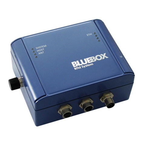
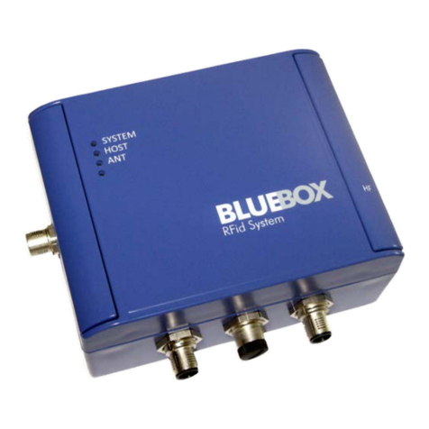
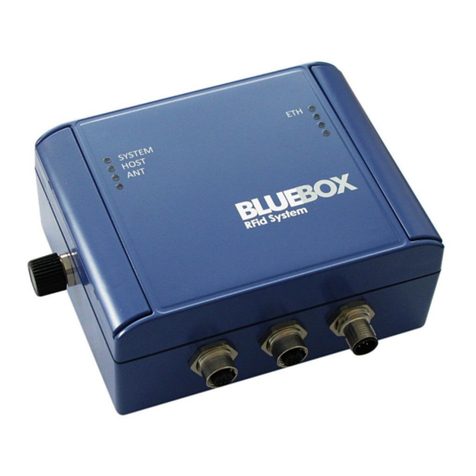
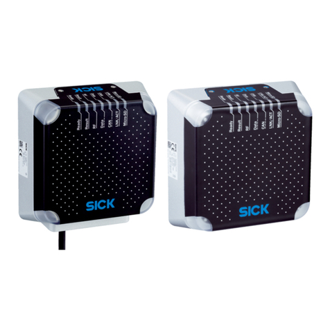
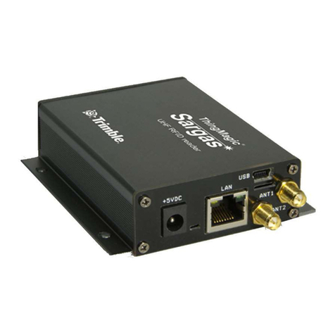
BlueBox IDTRONIC CX Industrial UHF User manual

BLUEBOX CX Industrial UHF Page 1 of 126
UHF
RFID System
BLUEBOX CX Industrial UHF

BLUEBOX CX Industrial UHF Page 2 of 126
Preface
iDTRONIC GmbH (IDTRONIC) reserves the right to make changes to its products
or services or to discontinue any product or service at any time without notice.
IDTRONIC provides customer assistance in various technical areas, but, does
not have full access to data concerning the use and applications of customer's
products. Therefore, IDTRONIC assumes no liability and is not responsible for
customer applications or product or software design or performance relating to
systems or applications incorporating IDTRONIC products. In addition,
IDTRONIC assumes no liability and is not responsible for infringement of patents
and/or any other intellectual or industrial property rights of third parties, which
may result from assistance provided by IDTRONIC. IDTRONIC products are not
designed, intended, authorized or warranted to be suitable for life support
applications or any other life critical applications that could involve potential risk
of death, personal injury or severe property or environmental damage. With the
edition of this document, all previous editions become void. Indications made in
this manual may be changed without previous notice. Composition of the
information in this manual has been done to the best of our knowledge.
IDTRONIC does not guarantee the correctness and completeness of the details
given in this manual and may not be held liable for damages ensuing from
incorrect or incomplete information. Since, despite all our efforts, errors may not
be completely avoided, we are always grateful for your useful tips. The
installation instructions given in this manual are based on advantageous
boundary conditions. IDTRONIC does not give any guarantee promise for perfect
function in cross environments. The companies or products mentioned in this
document might be brands or brand names of the different suppliers or their
subsidiaries in any country. This document may be downloaded onto a computer,
stored and duplicated as necessary to support the use of the related IDTRONIC
products. Any other type of duplication, circulation or storage on data carriers in
any manner not authorized by IDTRONIC represents a violation of the applicable
copyright laws and shall be prosecuted.
iDTRONIC GmbH
Ludwig-Reichling-Straße 4
67059 Ludwigshafen
Germany/Deutschland
Phone: +49 621 6690094-0
Fax: +49 621 6690094-9
Web: idtronic.de
Issue 2.30
–11. January 2021 –
Subject to alteration without prior notice.
© Copyright iDTRONIC GmbH 2021
Printed in Germany

BLUEBOX CX Industrial UHF Page 3 of 126
Safety Instructions / Warning - Read before start-up!
•The device may only be used for the intended purpose designed by the
manufacturer. The operation manual should be conveniently kept available
at all times for each user.
•Unauthorized changes and the use of spare parts and additional devices
that have not been sold or recommended by the manufacturer may cause
fire, electric shocks or injuries. Such unauthorized measures shall exclude
any liability by the manufacturer.
•The liability-prescriptions of the manufacturer in the issue valid at the time
of purchase are valid for the device. The manufacturer shall not be held
legally responsible for inaccuracies, errors, or omissions in the manual or
automatically set parameters for a device or for an incorrect application of
a device.
•Repairs may be executed by the manufacturer only.
•Only qualified personnel should carry out installation, operation, and
maintenance procedures.
•Use of the device and its installation must be in accordance with national
legal requirements and local electrical codes.
•When working on devices the valid safety regulations must be observed.
IP67

BLUEBOX CX Industrial UHF Page 4 of 126
This manual applies to the following devices:
Description:
Order Number:
Mid Range read / write UHF RFID device with integrated
antenna. Serial and Ethernet 10-100M on Amphenol RJF
connector communication interface. EU1 (865 MHz …
868MHz) version.
5325U
Mid Range read / write UHF RFID device with integrated
antenna. Serial and Ethernet 10-100M on Amphenol RJF
connector communication interface. FCC (902 MHz …
928MHz) version.
5325U-FCC
Mid Range read / write UHF RFID device with integrated
antenna. Serial and Ethernet 10-100M on Amphenol RJF
connector communication interface. Brazil (902 MHz …
928MHz) version.
5325U-BRA
Mid Range read / write UHF RFID device with integrated
antenna and RTC (Real Time Clock). Serial and Ethernet
10-100M on Amphenol RJF connector communication
interface. EU1 (865 MHz … 868MHz) version.
5325U-RTC
Mid Range read / write UHF RFID device with integrated
antenna and RTC (Real Time Clock). Serial and Ethernet
10-100M on Amphenol RJF connector communication
interface. FCC (902 MHz … 928MHz) version.
5325U-RTC-FCC
Mid Range read / write UHF RFID device with integrated
antenna and RTC (Real Time Clock). Serial and Ethernet
10-100M on Amphenol RJF connector communication
interface. Brazil (902 MHz … 928MHz) version.
5325U-RTC-BRA
Long Range read / write UHF RFID device with 1
external antenna. Serial and Ethernet 10-100M on
Amphenol RJF connector communication interface. EU1
(865 MHz … 868MHz) version.
5335U
Long Range read / write UHF RFID device with 1
external antenna. Serial and Ethernet 10-100M on
Amphenol RJF connector communication interface. FCC
(902 MHz … 928MHz) version.
5335U-FCC
Long Range read / write UHF RFID device with 1
external antenna. Serial and Ethernet 10-100M on
Amphenol RJF connector communication interface.
Brazil (902 MHz … 928MHz) version.
5335U-BRA
Long Range read / write UHF RFID device with 1
external antenna and RTC (Real Time Clock). Serial and
Ethernet 10-100M on Amphenol RJF connector
communication interface. EU1 (865 MHz … 868MHz)
version.
5335U-RTC

BLUEBOX CX Industrial UHF Page 5 of 126
Description:
Order Number:
Long Range read / write UHF RFID device with 1
external antenna and RTC (Real Time Clock). Serial and
Ethernet 10-100M on Amphenol RJF connector
communication interface. FCC (902 MHz … 928MHz)
version.
5335U-RTC-FCC
Long Range read / write UHF RFID device with 1
external antenna and RTC (Real Time Clock). Serial and
Ethernet 10-100M on Amphenol RJF connector
communication interface. Brazil (902 MHz … 928MHz)
version.
5335U-RTC-BRA
Long Range read / write UHF RFID device with up to 2
external antennas. Serial and Ethernet 10-100M on
Amphenol RJF connector communication interface. EU1
(865 MHz … 868MHz) version.
5345U
Long Range read / write UHF RFID device with up to 2
external antennas. Serial and Ethernet 10-100M on
Amphenol RJF connector communication interface. FCC
(902 MHz … 928MHz) version.
5345U-FCC
Long Range read / write UHF RFID device with up to 2
external antennas. Serial and Ethernet 10-100M on
Amphenol RJF connector communication interface.
Brazil (902 MHz … 928MHz) version.
5345U-BRA
Long Range read / write UHF RFID device with up to 2
external antennas and RTC (Real Time Clock). Serial
and Ethernet 10-100M on Amphenol RJF connector
communication interface. EU1 (865 MHz … 868MHz)
version.
5345U-RTC
Long Range read / write UHF RFID device with up to 2
external antennas and RTC (Real Time Clock). Serial
and Ethernet 10-100M on Amphenol RJF connector
communication interface. FCC (902 MHz … 928MHz)
version.
5345U-RTC-FCC
Long Range read / write UHF RFID device with up to 2
external antennas and RTC (Real Time Clock). Serial
and Ethernet 10-100M on Amphenol RJF connector
communication interface. Brazil (902 MHz … 928MHz)
version.
5345U-RTC-BRA
Mid Range read / write UHF RFID device with integrated
antenna. Serial and Ethernet 10-100M on M12 4 poles
D-coded female connector communication interface.
EU1 (865 MHz … 868MHz) version.
5326U
Mid Range read / write UHF RFID device with integrated
antenna. Serial and Ethernet 10-100M on M12 4 poles
5326U-FCC

BLUEBOX CX Industrial UHF Page 6 of 126
Description:
Order Number:
D-coded female connector communication interface.
FCC (902 MHz … 928MHz) version.
Mid Range read / write UHF RFID device with integrated
antenna. Serial and Ethernet 10-100M on M12 4 poles
D-coded female connector communication interface.
Brazil (902 MHz … 928MHz) version.
5326U-BRA
Mid Range read / write UHF RFID device with integrated
antenna and RTC (Real Time Clock). Serial and Ethernet
10-100M on M12 4 poles D-coded female connector
communication interface. EU1 (865 MHz … 868MHz)
version.
5326U-RTC
Mid Range read / write UHF RFID device with integrated
antenna and RTC (Real Time Clock). Serial and Ethernet
10-100M on M12 4 poles D-coded female connector
communication interface. FCC (902 MHz … 928MHz)
version.
5326U-RTC-FCC
Mid Range read / write UHF RFID device with integrated
antenna and RTC (Real Time Clock). Serial and Ethernet
10-100M on M12 4 poles D-coded female connector
communication interface. Brazil (902 MHz … 928MHz)
version.
5326U-RTC-BRA
Long Range read / write UHF RFID device with 1
external antenna. Serial and Ethernet 10-100M on M12
4 poles D-coded female connector communication
interface. EU1 (865 MHz … 868MHz) version.
5336U
Long Range read / write UHF RFID device with 1
external antenna. Serial and Ethernet 10-100M on M12
4 poles D-coded female connector communication
interface. FCC (902 MHz … 928MHz) version.
5336U-FCC
Long Range read / write UHF RFID device with 1
external antenna. Serial and Ethernet 10-100M on M12
4 poles D-coded female connector communication
interface. Brazil (902 MHz … 928MHz) version.
5336U-BRA
Long Range read / write UHF RFID device with 1
external antenna and RTC (Real Time Clock). Serial and
Ethernet 10-100M on M12 4 poles D-coded female
connector communication interface. EU1 (865 MHz …
868MHz) version.
5336U-RTC
Long Range read / write UHF RFID device with 1
external antenna and RTC (Real Time Clock). Serial and
Ethernet 10-100M on M12 4 poles D-coded female
connector communication interface. FCC (902 MHz …
928MHz) version.
5336U-RTC-FCC

BLUEBOX CX Industrial UHF Page 7 of 126
Description:
Order Number:
Long Range read / write UHF RFID device with 1
external antenna and RTC (Real Time Clock). Serial and
Ethernet 10-100M on M12 4 poles D-coded female
connector communication interface. Brazil (902 MHz …
928MHz) version.
5336U-RTC-BRA
Long Range read / write UHF RFID device with up to 2
external antennas. Serial and Ethernet 10-100M on M12
4 poles D-coded female connector communication
interface. EU1 (865 MHz … 868MHz) version.
5346U
Long Range read / write UHF RFID device with up to 2
external antennas. Serial and Ethernet 10-100M on M12
4 poles D-coded female connector communication
interface. FCC (902 MHz … 928MHz) version.
5346U-FCC
Long Range read / write UHF RFID device with up to 2
external antennas. Serial and Ethernet 10-100M on M12
4 poles D-coded female connector communication
interface. Brazil (902 MHz … 928MHz) version.
5346U-BRA
Long Range read / write UHF RFID device with up to 2
external antennas and RTC (Real Time Clock). Serial
and Ethernet 10-100M on M12 4 poles D-coded female
connector communication interface. EU1 (865 MHz …
868MHz) version.
5346U-RTC
Long Range read / write UHF RFID device with up to 2
external antennas and RTC (Real Time Clock). Serial
and Ethernet 10-100M on M12 4 poles D-coded female
connector communication interface. FCC (902 MHz …
928MHz) version.
5346U-RTC-FCC
Long Range read / write UHF RFID device with up to 2
external antennas and RTC (Real Time Clock). Serial
and Ethernet 10-100M on M12 4 poles D-coded female
connector communication interface. Brazil (902 MHz …
928MHz) version.
5346U-RTC-BRA
Long Range read / write UHF RFID device with up to 2
external antennas. Bluetooth and Ethernet 10-100M on
M12 4 poles D-coded female connector communication
interface. EU1 (865 MHz … 868MHz) version.
5346U-BL
Long Range read / write UHF RFID device with up to 2
external antennas. Bluetooth and Ethernet 10-100M on
M12 4 poles D-coded female connector communication
interface. FCC (902 MHz … 928MHz) version.
5346U-BL-FCC
Long Range read / write UHF RFID device with up to 2
external antennas. Bluetooth and Ethernet 10-100M on
5346U-BL-BRA

BLUEBOX CX Industrial UHF Page 8 of 126
Description:
Order Number:
M12 4 poles D-coded female connector communication
interface. Brazil (902 MHz … 928MHz) version.
Mid Range read / write UHF RFID (EU) device with
integrated antenna. Serial and data bus communication
interface. EU1 (865 MHz … 868MHz) version.
5327U
Mid Range read / write UHF RFID (US) device with
integrated antenna. Serial and data bus communication
interface. FCC (902 MHz … 928MHz) version.
5327U-FCC
Mid Range read / write UHF RFID (US) device with
integrated antenna. Serial and data bus communication
interface. Brazil (902 MHz … 928MHz) version.
5327U-BRA
Long Range read / write UHF RFID device with 1
external antenna. Serial and data bus communication
interface. EU1 (865 MHz … 868MHz) version.
5337U
Long Range read / write UHF RFID device with 1
external antenna. Serial and data bus communication
interface. FCC (902 MHz … 928MHz) version.
5337U-FCC
Long Range read / write UHF RFID device with 1
external antenna. Serial and data bus communication
interface. Brazil (902 MHz … 928MHz) version.
5337U-BRA
Long Range read / write UHF RFID device with up to 2
external antennas. Serial and data bus communication
interface. EU1 (865 MHz … 868MHz) version.
5347U
Long Range read / write UHF RFID device with up to 2
external antennas. Serial and data bus communication
interface. FCC (902 MHz … 928MHz) version.
5347U-FCC
Long Range read / write UHF RFID device with up to 2
external antennas. Serial and data bus communication
interface. Brazil (902 MHz … 928MHz) version.
5347U-BRA
Mid Range read / write UHF RFID device with integrated
antenna. CAN bus and Ethernet 10-100M on M12 4
poles D-coded female connector communication
interface. EU1 (865 MHz … 868MHz) version.
5328U
Mid Range read / write UHF RFID device with integrated
antenna. CAN bus and Ethernet 10-100M on M12 4
poles D-coded female connector communication
interface. FCC (902 MHz … 928MHz) version.
5328U-FCC
Mid Range read / write UHF RFID device with integrated
antenna. CAN bus and Ethernet 10-100M on M12 4
poles D-coded female connector communication
interface. Brazil (902 MHz … 928MHz) version.
5328U-BRA

BLUEBOX CX Industrial UHF Page 9 of 126
Description:
Order Number:
Mid Range read / write UHF RFID device with integrated
antenna and RTC (Real Time Clock). CAN bus and
Ethernet 10-100M on M12 4 poles D-coded female
connector communication interface. EU1 (865 MHz …
868MHz) version.
5328U-RTC
Mid Range read / write UHF RFID device with integrated
antenna and RTC (Real Time Clock). CAN bus and
Ethernet 10-100M on M12 4 poles D-coded female
connector communication interface. FCC (902 MHz …
928MHz) version.
5328U-RTC-FCC
Mid Range read / write UHF RFID device with integrated
antenna and RTC (Real Time Clock). CAN bus and
Ethernet 10-100M on M12 4 poles D-coded female
connector communication interface. Brazil (902 MHz …
928MHz) version.
5328U-RTC-BRA
Long Range read / write UHF RFID device with 1
external antenna. CAN bus and Ethernet 10-100M on
M12 4 poles D-coded female connector communication
interface. EU1 (865 MHz … 868MHz) version.
5338U
Long Range read / write UHF RFID device with 1
external antenna. CAN bus and Ethernet 10-100M on
M12 4 poles D-coded female connector communication
interface. FCC (902 MHz … 928MHz) version.
5338U-FCC
Long Range read / write UHF RFID device with 1
external antenna. CAN bus and Ethernet 10-100M on
M12 4 poles D-coded female connector communication
interface. Brazil (902 MHz … 928MHz) version.
5338U-BRA
Long Range read / write UHF RFID device with 1
external antenna with RTC (Real Time Clock). CAN bus
and Ethernet 10-100M on M12 4 poles D-coded female
connector communication interface. EU1 (865 MHz …
868MHz) version.
5338U-RTC
Long Range read / write UHF RFID device with 1
external antenna with RTC (Real Time Clock). CAN bus
and Ethernet 10-100M on M12 4 poles D-coded female
connector communication interface. FCC (902 MHz …
928MHz) version.
5338U-RTC-FCC
Long Range read / write UHF RFID device with 1
external antenna with RTC (Real Time Clock). CAN bus
and Ethernet 10-100M on M12 4 poles D-coded female
connector communication interface. Brazil (902 MHz …
928MHz) version.
5338U-RTC-BRA
Long Range read / write UHF RFID device with up to 2
external antennas. CAN bus and Ethernet 10-100M on
5348U

BLUEBOX CX Industrial UHF Page 10 of 126
Description:
Order Number:
M12 4 poles D-coded female connector communication
interface. EU1 (865 MHz … 868MHz) version.
Long Range read / write UHF RFID device with up to 2
external antennas. CAN bus and Ethernet 10-100M on
M12 4 poles D-coded female connector communication
interface. FCC (902 MHz … 928MHz) version.
5348U-FCC
Long Range read / write UHF RFID device with up to 2
external antennas. CAN bus and Ethernet 10-100M on
M12 4 poles D-coded female connector communication
interface. Brazil (902 MHz … 928MHz) version.
5348U-BRA
Long Range read / write UHF RFID device with up to 2
external antennas with RTC (Real Time Clock). CAN bus
and Ethernet 10-100M on M12 4 poles D-coded female
connector communication interface. EU1 (865 MHz …
868MHz) version.
5348U-RTC
Long Range read / write UHF RFID device with up to 2
external antennas with RTC (Real Time Clock). CAN bus
and Ethernet 10-100M on M12 4 poles D-coded female
connector communication interface. FCC (902 MHz …
928MHz) version.
5348U-RTC-FCC
Long Range read / write UHF RFID device with up to 2
external antennas with RTC (Real Time Clock). CAN bus
and Ethernet 10-100M on M12 4 poles D-coded female
connector communication interface. Brazil (902 MHz …
928MHz) version.
5348U-RTC-BRA
This manual is valid as of firmware version:
Order Number
Hardware Version
Firmware Version
5325U
2
2.70B
5325U-FCC
2
2.70B
5325U-BRA
2
2.70B
5325U-RTC
2
2.70T
5325U-RTC-FCC
2
2.70T
5325U-RTC-BRA
2
2.70T
5335U
2
2.70A
5335U-FCC
2
2.70A

BLUEBOX CX Industrial UHF Page 11 of 126
Order Number
Hardware Version
Firmware Version
5335U-BRA
2
2.70A
5335U-RTC
2
2.70S
5335U-RTC-FCC
2
2.70S
5335U-RTC-BRA
2
2.70S
5345U
2
2.70
5345U-FCC
2
2.70
5345U-BRA
2
2.70
5345U-RTC
2
2.70R
5345U-RTC-FCC
2
2.70R
5345U-RTC-BRA
2
2.70R
5326U
2
2.70B
5326U-FCC
2
2.70B
5326U-BRA
2
2.70B
5326U-RTC
2
2.70T
5326U-RTC-FCC
2
2.70T
5326U-RTC-BRA
2
2.70T
5336U
2
2.70A
5336U-FCC
2
2.70A
5336U-BRA
2
2.70A
5336U-RTC
2
2.70S
5336U-RTC-FCC
2
2.70S
5336U-RTC-BRA
2
2.70S
5346U
2
2.70
5346U-FCC
2
2.70
5346U-BRA
2
2.70
5346U-RTC
2
2.70R
5346U-RTC-FCC
2
2.70R
5346U-RTC-BRA
2
2.70R

BLUEBOX CX Industrial UHF Page 12 of 126
Order Number
Hardware Version
Firmware Version
5346U-BL
2
2.65L
5346U-BL-FCC
2
2.65L
5346U-BL-BRA
2
2.65L
5327U
2
2.70B
5327U-FCC
2
2.70B
5327U-BRA
2
2.70B
5337U
2
2.70A
5337U-FCC
2
2.70A
5337U-BRA
2
2.70A
5347U
2
2.70
5347U-FCC
2
2.70
5347U-BRA
2
2.70
5328U
2
2.70B
5328U-FCC
2
2.70B
5328U-BRA
2
2.70B
5328U-RTC
2
2.70T
5328U-RTC-FCC
2
2.70T
5328U-RTC-BRA
2
2.70T
5338U
2
2.70A
5338U-FCC
2
2.70A
5338U-BRA
2
2.70A
5338U-RTC
2
2.70S
5338U-RTC-FCC
2
2.70S
5338U-RTC-BRA
2
2.70S
5348U
2
2.70
5348U-FCC
2
2.70
5348U-BRA
2
2.70
5348U-RTC
2
2.70R

BLUEBOX CX Industrial UHF Page 13 of 126
Order Number
Hardware Version
Firmware Version
5348U-RTC-FCC
2
2.70R
5348U-RTC-BRA
2
2.70R
Hereinafter the product identification system:
5
3
x
y
U
-opt1
-opt2
-rrr
Antenna
Interface
Option #1
Option #2
RF Region
Antenna
2
1 integrated antenna
3
1 external antenna
4
Up to 2 external antennas
Interface:
5
=
Serial + Ethernet 10-100M on Amphenol RJF
6
=
Serial + Ethernet 10-100M on M12 cod. D
7
=
Serial + data bus interface
8
=
CAN bus + Ethernet 10-100M on M12 cod. D
Option #1:
Blank
=
Without options
-RTC
=
With Real Time Clock (RTC)
Option #2:
Blank
=
Wihtout options
-BL
=
With Bluetooth interface
RF Region:
Blank
=
EU1 (865 MHz … 868 MHz)
-FCC
=
FCC (902 MHz … 928 MHz)
-BRA
=
Brazil (902 MHz … 928 MHz)

BLUEBOX CX Industrial UHF Page 14 of 126
Table of Contents
1Introduction.....................................................................................17
2Technical Specifications.....................................................................18
2.1 Electrical Features.......................................................................18
2.1.1 Electrical Features 5325U-opt1-rrr..........................................18
2.1.2 Electrical Features 5326U-opt1-rrr..........................................19
2.1.3 Electrical Features 5327U-rrr .................................................19
2.1.4 Electrical Features 5328U-opt1-rrr..........................................20
2.1.5 Electrical Features 5335U-opt1-rrr..........................................21
2.1.6 Electrical Features 5336U-opt1-rrr..........................................22
2.1.7 Electrical Features 5337U-rrr .................................................23
2.1.8 Electrical Features 5338U-opt1-rrr..........................................24
2.1.9 Electrical Features 5345U-opt1-rrr..........................................24
2.1.10 Electrical Features 5346U-opt1-rrr..........................................25
2.1.11 Electrical Features 5346U-BL-rrr ............................................26
2.1.12 Electrical Features 5347U-rrr .................................................27
2.1.13 Electrical Features 5348U-opt1-rrr..........................................28
2.2 Mechanical Features ....................................................................29
2.3 Environmental Conditions.............................................................29
2.4 Reading Performance Tests ..........................................................29
3Operating Features ...........................................................................30
3.1 General Parameters.....................................................................37
3.2 Configuration Parameters.............................................................39
3.2.1 Ethernet Interface ................................................................39
3.2.2 Remote Server.....................................................................40
3.2.3 Auto Connection...................................................................43
3.2.4 Bluetooth Interface...............................................................44
3.2.5 Data Bus Interface ...............................................................45
3.2.6 CAN Bus Interface ................................................................47
3.2.7 Input / Output .....................................................................48
3.2.8 ‘Spontaneous’ Message .........................................................52
3.2.9 RF and EPC C1G2 (Class-1 Gen-2)..........................................55
3.2.10 Dynamic RF Transmit Power ..................................................64
3.2.11 RF Antenna Tuning ...............................................................65
3.3 Device Status .............................................................................66
4Device Startup .................................................................................67
5‘BLUEBOX Serial Config’ Software .......................................................69
5.1 Software Startup ........................................................................69
5.2 Menu.........................................................................................69
5.2.1 File Menu ............................................................................70
5.2.2 Info Menu ...........................................................................70
5.3 Software Usage ..........................................................................71
6Installation ......................................................................................72
6.1 General Instructions ....................................................................72

BLUEBOX CX Industrial UHF Page 15 of 126
6.2 Notes on Tag Mounting ................................................................72
6.3 Avoiding Interference ..................................................................72
6.4 Mechanical Design.......................................................................73
6.4.1 Mechanical Design 532yU-opt1-rrr..........................................73
6.4.2 Mechanical Design 533yU-opt1-rrr..........................................74
6.4.3 Mechanical Design 534yU-opt1-rrr..........................................74
6.5 Fixing ........................................................................................74
6.6 Mounting Distances .....................................................................75
6.6.1 Mounting Distances 532yU-opt1-rrr ........................................75
6.7 Positioning of the Tags.................................................................76
6.7.1 Positioning of the Tags 532yU-opt1-rrr ...................................76
6.8 Main Board.................................................................................77
6.9 Serial Interface Board..................................................................78
7Electrical Connections .......................................................................79
7.1 Wiring .......................................................................................79
7.1.1 Wiring 5325U-opt1-rrr ..........................................................79
7.1.2 Wiring 5326U-opt1-rrr ..........................................................80
7.1.3 Wiring 5327U-rrr..................................................................80
7.1.4 Wiring 5328U-opt1-rrr ..........................................................81
7.1.5 Wiring 5335U-opt1-rrr ..........................................................81
7.1.6 Wiring 5336U-opt1-rrr ..........................................................82
7.1.7 Wiring 5337U-rrr..................................................................82
7.1.8 Wiring 5338U-opt1-rrr ..........................................................83
7.1.9 Wiring 5345U-opt1-rrr ..........................................................83
7.1.10 Wiring 5346U-opt1-rrr ..........................................................84
7.1.11 Wiring 5346U-BL-rrr .............................................................84
7.1.12 Wiring 5347U-rrr..................................................................85
7.1.13 Wiring 5348U-opt1-rrr ..........................................................85
7.2 Power Supply and Serial Line Connection (a1) ................................86
7.3 Power Supply and CAN Bus Connection (a2)...................................87
7.4 Power Supply Connection (a3) ......................................................88
7.5 Input / Output Connection (b) ......................................................89
7.6 Ethernet Interface Connection (c1)................................................90
7.7 Ethernet Interface Connection (c2)................................................90
7.8 Data Bus Interface Connection (d) ................................................91
8Wiring Examples...............................................................................93
9Status Indications.............................................................................94
10 Antenna ..........................................................................................96
11 Maintenance, Repair and Disposal.......................................................97
12 Regulatory Compliance......................................................................98
12.1 CE Compliance.........................................................................98
13 Mechanical Drawings.........................................................................99
13.1 Mechanical Drawings 5325U-opt1-rrr..........................................99
13.2 Mechanical Drawings 5326U-opt1-rrr..........................................99
13.3 Mechanical Drawings 5327U-rrr ...............................................100
13.4 Mechanical Drawings 5328U-opt1-rrr........................................100

BLUEBOX CX Industrial UHF Page 16 of 126
13.5 Mechanical Drawings 5335U-opt1-rrr........................................101
13.6 Mechanical Drawings 5336U-opt1-rrr........................................101
13.7 Mechanical Drawings 5337U-rrr ...............................................102
13.8 Mechanical Drawings 5338U-opt1-rrr........................................102
13.9 Mechanical Drawings 5345U-opt1-rrr........................................103
13.10 Mechanical Drawings 5346U-opt1-rrr ........................................103
13.11 Mechanical Drawings 5346U-BL-rrr...........................................104
13.12 Mechanical Drawings 5347U-rrr ...............................................104
13.13 Mechanical Drawings 5348U-opt1-rrr ........................................105
14 Document Revision History ..............................................................106
A. Regions of Operation.......................................................................113
A.1. Operation in Europe ..................................................................113
A.2. Operation in North America ........................................................114
A.3. Operation in Brazil ....................................................................115
B. RS232 DB9 to M12 Connection.........................................................118
C. .inf File..........................................................................................119
D. Driver Install on Windows 8 OS ........................................................121

BLUEBOX CX Industrial UHF Page 17 of 126
1Introduction
The BLUEBOX CX INDUSTRIAL UHF hereinafter named BLUEBOX is an UHF
read / write RFID device operating in the 840 MHz to 960 MHz frequency band
and suitable for industrial application, it communicates with a ‘host’ system
(typically a PC or a PLC) through a RS232 / RS485 serial line and a 10-100M
Ethernet connection (items 53x5U-opt1-rrr and 53x6U-opt1-rrr). Versions with
data bus (items 53x7U-rrr), CAN bus (items 53x8U-opt1-rrr) or Bluetooth
connection (item 5346U-BL-rrr) are also available The BLUEBOX acts as a joint
through a set of commands between the host system and one or more RFID
transponders (or tags) present near the antennas. It is available with one
integrated antenna (items 532xU-opt1-rrr]) or up to two external antennas with
TNC connections (items 533xU-opt1-rrr and 534xU-opt1-rrr) allowing good read
range (up to 10 m) and directivity in function of the characteristics and
positioning of the antennas and tags. The same 'master/slave' protocol is used
for the communication between the host system (‘master’) and the BLUEBOX
(‘slave’), independently of the kind of connection (point to point, multipoint or
Ethernet). Through these communication channels, it is also possible to
configure the functional parameters and to upgrade the firmware, the ‘BLUEBOX
Show’ software of the SDK is foreseen to explicate these operations.
Furthermore the BLUEBOX is able to handle two digital outputs (relays) and two
optoisolated digital inputs. BLUEBOX is designed and developed to allow
installation and maintenance experts to perform all power supply,
communication and interfacing I/O connections without the need to open the
device.

BLUEBOX CX Industrial UHF Page 18 of 126
2Technical Specifications
This section provides details on the technical specifications of the BLUEBOX.
2.1 Electrical Features
This section provides details on the electrical features of the BLUEBOX.
2.1.1 Electrical Features 5325U-opt1-rrr
Power Supply
10 … 36 Vdc or
PoE IEEE802.3af-2003 Mode A / Mode B
Power Rating
15W @RFout=27dBm
Operating Frequency
EU1: 865 MHz … 868 MHz
FCC: 902 MHz … 928MHz
BRA: 902 MHz … 928 MHz
RF Transmit Power
Max 0.5W (27dBm) conducted
RF Receive Sensitivity
Max -85dBm
Antenna
Integrated
Reading Distance
4 mt1
Supported Transponders
ISO 18000-632(EPC Class-1 Gen-2 V2)
Communication Interface
Serial RS232 / RS485
Ethernet 10-100M
Service Interface
USB Virtual Com (on the board and not
available on the external)
Digital Inputs
2 opto-isolated input, 10Vdc … 36Vdc, Max
current 20mA @24Vdc, debounce 16ms
Digital Outputs
2 outputs (relay), NO/NC contacts, Max 1A
@30Vdc
Status Display
3 LEDs, Buzzer
Connections
2 M12 Connectors (5-poles A-coded male for
power supply, 12-poles A-coded female for
I/O) and Amphenol RJF 544 for Ethernet
1
Reading distance depends on transponder type, antenna and environmental conditions.
2
ISO 18000-6C became ISO 18000-63 in 2012 due to ISO naming rules that do not allow letters in standards names.

BLUEBOX CX Industrial UHF Page 19 of 126
2.1.2 Electrical Features 5326U-opt1-rrr
Power Supply
10 … 36 Vdc or
PoE IEEE802.3af-2003 Mode A
Power Rating
15W @RFout=27dBm
Operating Frequency
EU1: 865 MHz … 868 MHz
FCC: 902 MHz … 928MHz
BRA: 902 MHz … 928 MHz
RF Transmit Power
Max 0.5W (27dBm) conducted
RF Receive Sensitivity
Max -85dBm
Antenna
Integrated
Reading Distance
4 mt3
Supported Transponders
ISO 18000-634(EPC Class-1 Gen-2 V2)
Communication Interface
Serial RS232 / RS485
Ethernet 10-100M
Service Interface
USB Virtual Com (on the board and not
available on the external)
Digital Inputs
2 opto-isolated input, 10Vdc … 36Vdc, Max
current 20mA @24Vdc, debounce 16ms
Digital Outputs
2 outputs (relay), NO/NC contacts, Max 1A
@30Vdc
Status Display
3 LEDs, Buzzer
Connections
3 M12 Connectors (5-poles A-coded male for
power supply, 12-poles A-coded female for
I/O, 4-poles D-coded female for Ethernet)
2.1.3 Electrical Features 5327U-rrr
Power Supply
10 … 36 Vdc
Power Rating
15W @RFout=27dBm
Operating Frequency
EU1: 865 MHz … 868 MHz
FCC: 902 MHz … 928MHz
3
Reading distance depends on transponder type, antenna and environmental conditions.
4
ISO 18000-6C became ISO 18000-63 in 2012 due to ISO naming rules that do not allow letters in standards names.

BLUEBOX CX Industrial UHF Page 20 of 126
BRA: 902 MHz … 928 MHz
RF Transmit Power
Max 0.5W (27dBm) conducted
RF Receive Sensitivity
Max -85dBm
Antenna
Integrated
Reading Distance
4 mt5
Supported Transponders
ISO 18000-636(EPC Class-1 Gen-2 V2)
Communication Interface
Serial RS232 / RS485
Data bus (Wiegand Data-0, Data-1)
Service Interface
USB Virtual Com (on the board and not
available on the external)
Digital Inputs
2 opto-isolated input, 10Vdc … 36Vdc, Max
current 20mA @24Vdc, debounce 16ms
Digital Outputs
2 outputs (relay), NO/NC contacts, Max 1A
@30Vdc
Status Display
3 LEDs, Buzzer
Connections
3 M12 Connectors (5-poles A-coded male for
power supply and serial interface, 12-poles
A-coded female for I/O, 5-poles A-coded
female for data bus)
2.1.4 Electrical Features 5328U-opt1-rrr
Power Supply
10 … 36 Vdc
Power Rating
15W @RFout=27dBm
Operating Frequency
EU1: 865 MHz … 868 MHz
FCC: 902 MHz … 928MHz
BRA: 902 MHz … 928 MHz
RF Transmit Power
Max 0.5W (27dBm) conducted
RF Receive Sensitivity
Max -85dBm
Antenna
Integrated
Reading Distance
4 mt7
5
Reading distance depends on transponder type, antenna and environmental conditions.
6
ISO 18000-6C became ISO 18000-63 in 2012 due to ISO naming rules that do not allow letters in standards names.
7
Reading distance depends on transponder type, antenna and environmental conditions.
Table of contents
Other BlueBox RFID System manuals
