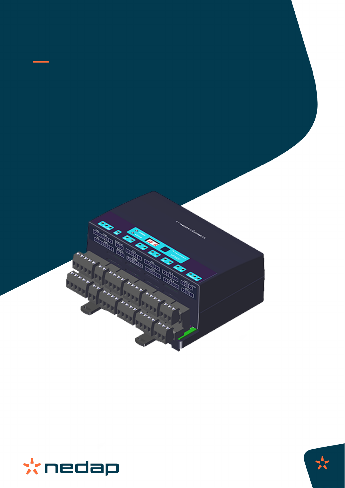
Nedap VP1007-B User manual
Instruction Manual
VP1007-B
Installation manual
Version 01.000 / November 2020 / EN
Original instructions
Livestock Management

Copyright
Copyright © Nedap N.V. All rights reserved. The information in this document is subject to change without
notice, it is not to be reproduced in any way, in whole or in part, without the written consent of Nedap N.V. All
trademarks referenced belong to their respective owners.
Disclaimer
Nedap N.V. has made every effort to ensure the accuracy of the information contained in this document.
However, Nedap N.V. makes no representations or warranties whatsoever whether express or implied as
to the accuracy, correctness, completeness or fit-for-purpose or suitability for the purpose of this product.
You use the products at your own risk. Nedap N.V. excludes any liability to the maximum extent permitted by
applicable law for the damages caused by errors or failures made during the installation or improper use of
this product or by not applying the instructions stated in this document. Nedap N.V. reserves the right to make
improvements or amendments to this document and/or the products described therein at any time without any
notification. The latest version of this document can be found on the Nedap Livestock Management business
portal (www.nedap.com/livestockmanagement-portal). Please download the latest version of this document (by
yourself or reseller) and keep a copy for your own records. This document can be published in various languages
but only the English language version will prevail. Nedap N.V. assumes no responsibility for any errors caused for
the translations into another language.
Warranty and spare parts
Please consult the Nedap products dealer from whom you purchased this product, in regards to the applicable
warranty conditions. This product cannot be used for any other purpose as described in this document. If
the product is not installed according to this document; the warranty provided is not applicable. At the sole
discretion of Nedap N.V., Nedap N.V. may decide to change the conditions of the warranty policy. You agree
that Nedap N.V. is able to compensate you the pro-rata value of the warranty involved rather than replacing
or repairing the product depending on the technical or economical value of the product. Prior to applying the
warranty, please verify if you comply with the warranty conditions of the warranty policy, whether you can
successfully apply for the replacement or repair of a defective part. Parts can only be replaced with original
Nedap parts, otherwise the warranty policy will not be applicable on the product. If the warranty is applicable,
please contact the dealer or send the defective parts to the dealer.
Additional information
For any information or questions regarding the product, please contact your own dealer.

VP1007-B / Installation manual
Version 01.000 / November 2020 / EN
1
Livestock Management
VP1007-B

VP1007-B / Installation manual
Version 01.000 / November 2020 / EN
2
Livestock Management
Content
1 Safety .................................................................................................. 3
2 VP1007-B introduction ......................................................................... 5
2.1 Extended functionality ................................................................................................... 5
3 Installation ........................................................................................... 6
3.1 Requirements for installation ........................................................................................ 6
3.1.1 Electrical requirements .................................................................................................... 6
3.1.2 Electromagnetic requirements ........................................................................................ 6
3.1.3 Tools requirements .......................................................................................................... 7
3.2 Mount the VP1007-B ..................................................................................................... 7
3.3 Wiring .............................................................................................................................. 7
3.3.1 Wiring diagram VP1007-B ............................................................................................... 9
4 Configuration ...................................................................................... 11
4.1 Configure the VP1007-B .............................................................................................. 11
4.2 Check for firmware updates ........................................................................................ 12
5 Commissioning ................................................................................... 13
5.1 Testing inputs and outputs .......................................................................................... 13
5.2 Antenna tuning ............................................................................................................. 14
5.3 Antenna adjustment ..................................................................................................... 14
5.4 Identification tests ....................................................................................................... 16
6 Troubleshooting .................................................................................. 18
7 Glossary ............................................................................................. 20
8 Technical specifications ...................................................................... 21
9 Handling instructions .......................................................................... 22
10 Compliance ........................................................................................ 23
11 Appendix ............................................................................................ 25
11.1 VP1007-B reader LED indicators ................................................................................ 25
11.2 VP1007-B reader menu overview ............................................................................... 26
11.3 Wiring color coding ...................................................................................................... 28
VP1007-B / Installation manual
Version 01.000 / November 2020 / EN
3
Livestock Management
1 Safety
Read this manual before using this product. Failure to follow the instructions and safety precautions in this
manual may result in serious injury or death. Keep this manual in a safe location for future reference.
Symbols used in the manual
Danger
Indicates a hazardous situation that, if not avoided, will result in death or serious
injury.
Warning
Indicates a hazardous situation that, if not avoided, could result in death or serious
injury.
Caution
Indicates a hazardous situation that, if not avoided, could result in minor or moderate
injury.
Indicates important information but not hazard related.
Suggestions and advice to perform certain tasks more easily.
General safety instructions
Warning
Always turn off the mains power supply when working on the electrical installation.
Warning
Always wear proper protection when installing and maintaining the VP1007-B.
Caution
Use the VP1007-B only with a suitable power supply. The power supply or power adapter must comply with
local regulations for a SELV, limited power (NEC class2, ps2) output (e.g. Nedap VP2001-B or Nedap power
adapter (P/N 9223126)).
Caution
Installation and service should only be done by locally qualified personnel.
Caution
Install the system according to the local rules and regulations.
Working environment
Caution
The installation area must be free from any obstacles, including animals.

VP1007-B / Installation manual
Version 01.000 / November 2020 / EN
4
Livestock Management
Caution
Make sure all components are installed out of reach of animals.
Caution
Make sure all cables are properly concealed, and form no danger for stumbling.
Caution
Take into account the high concentrations of ammonia when installing and maintaining the VP1007-B in pig
barns.
Animal welfare and safety
The automated actions of the Nedap Livestock Management systems do never discharge the installer and the
user of the system from his/her responsibility to assure and to take care of the well-being of the animals.

VP1007-B / Installation manual
Version 01.000 / November 2020 / EN
5
Livestock Management
2 VP1007-B introduction
The Nedap VP1007-B Transceiver is a reader and input/output controller that is used for feeding, weighing,
milking, heat detection, sorting/routing, identification and so on.
Connectors:
• 2 Antenna connections, 1 active at the time
• FDX sync / HDX sync
HDX and other extra ID options are only available by license. If no license is purchased for the VP1007-
B, these options can be tested for a 24-hour period.
• 1 CAN channel with 2 connectors
• 5 Outputs (max 2A)
• 5 Inputs
• 1 RS485 / RS232 communication channel
Features:
• Identification of tags
• Activates and controls e.g. lights, motors, valves, relays
• Reads the input for e.g. sensors, switches
• Special serial interface (RS485 / RS232) for connecting sensors with serial interface
All currently available Nedap Livestock antennas can be used.
2.1 Extended functionality
The new generation V-packs (V-pack B types) are based on a new transmitter-receiver module with an improved
way of animal identification based on Digital Signal Processing (DSP) technology.
The V-pack B types offer the following new features:
• Notch Filter (nF): This option suppresses the signals that are received from long wave transmitters near
Berlin, Frankfurt and Budapest. Especially large antennas such as the Walk Through and Walk Past antennas
are sensitive for this. Noise reduction antennas will not need this notch filter as they already suppress these
long wave transmitter signals.
These new options and the HDX mode must be activated with a license on the VPU (VP8001/VP8002). If the V-
pack is not connected to a VPU, a license for the V-pack must be purchased.
Nedap: If no license is purchased for the VPU or the V-pack, the HDX and/or Notch Filter options can be
tested for a 24-hour period. For more information see the menu overview of the V-pack in the Appendix.
To check if the VP1007 is a B version, a "b" will appear on the display shortly after the VP1007-B is booted.
If a system uses HDX tags, and a VP1007 has to be replaced with a VP1007-B, there are two options:
1. Order a special VP1007-B with HDX license pre-installed on the VP1007-B, or:
2. Order a normal VP1007-B FDX only and add a separate HDX license to the VPU for this VP1007-B.

VP1007-B / Installation manual
Version 01.000 / November 2020 / EN
6
Livestock Management
3 Installation
Do not operate the product without first reading this chapter and the safety section at the beginning of this
manual.
Warning
Failure to follow safety precautions in this chapter could result in serious injury or death.
3.1 Requirements for installation
3.1.1 Electrical requirements
Mains power
Make sure the mains power supply for the system is easily accessible and not too far away from the barn
in which the units are placed. The power sockets shall be installed near the equipment and must be easily
accessible.
Caution
Nedap power supplies must be connected to a power socket with protective earth (PE). Always use a 3-pole
connector with a PE contact.
If there is no PE available, create a PE next to the power socket to be used for each power supply. The
properties of a correct PE depend on local circumstances and legislation. Always comply with local rules and
regulations when installing earth electrodes.
Cabling
Install the Velos CAN cable(s) inside a plastic (PVC) conduit.
Do NOT install cables directly to metal ceiling, trusses, feed lines and power lines.
Lightning protection
It is important to follow closely the guidelines that are described in this section, in order to minimize risk of
damage on Velos systems in case of lightning. Nedap does, however, not accept any responsibility for damage
caused by high voltage (such as lightning), as described in the Warranty Policy.
Protective Earth (PE)
PE is meant for safety related issues such as electric shocks to humans or animals. PE will not protect devices
(sufficiently) when they are struck by lightning. Normally PE is situated next to the main power source only.
Grounding
Grounding is a connection to the ground, but not Protective Earth, for example a metal roof that is connected to
different earth electrodes in order to lead high peak currents (such as lightning) to the earth.
Nedap can never be kept responsible for incorrect functioning of networks or any damage arising from the
recommendations mentioned in this document.
3.1.2 Electromagnetic requirements
Nedap Animal Identification uses radio waves in compliance with ISO 11784/11785 standard and local
regulations.

VP1007-B / Installation manual
Version 01.000 / November 2020 / EN
7
Livestock Management
Notwithstanding all due precaution by Nedap, Nedap Animal Identification may not function optimally due
to devices that emit radio waves, such as (but not limited to) variable frequency drives, electronic ballasts of
lighting systems, power supplies, electronic converters of solar panels/windmills and (long) wave radio stations,
which may cause interference with Nedap Animal Identification.
No claims, representations or warranties, whether expressed or implied, are made by Nedap as to the
performance, reliability, durability and safety of Nedap Animal Identification used in conjunction with
abovementioned or other devices.
In order to achieve optimal performance of Nedap Animal Identification, the electrical installation on the farm
needs to meet the conditions that are shown below.
• Maximum allowed environmental noise level: 10 dBµA/m quasi peak, according to CISPR 16-1-1.
• Maximum allowed conducted noise: according to EN55032: 2015.
3.1.3 Tools requirements
• Screwdriver size 0.4 x 2.5 mm (0.016 x 0.098 in.) for the LAN connector of the V-pack.
3.2 Mount the VP1007-B
Mount the VP1007-B in a dust and splash proof housing, preferably a Nedap V-box:
If the VP1007-B is installed as a part of a complete Nedap system, use the installation manual of this
system. The installation manual can be obtained from your dealer or on our Business portal: http://
www.nedap.com/livestockmanagement-portal.
1. Mount the V-box according to the installation instructions of the V-box, which can be obtained from your
dealer or on our Business portal: http://www.nedap.com/livestockmanagement-portal.
2. Mount the VP1007-B in the V-box:
a. Pull down the 2 lips on the back side of the VP1007-B.
b. Place the VP1007-B on the top of the DIN rail inside the V-box.
c. Hinge down the VP1007-B until it clicks in.
d. Push up the 2 lips to secure the VP1007-B to the DIN rail.
3. Close the V-box.
Caution
Make sure to always close the V-box with the V-box cover and check the correct position of the cover
seal.
3.3 Wiring
Connectors
VP1007-B / Installation manual
Version 01.000 / November 2020 / EN
8
Livestock Management
Connector Symbol Description
Vout +Output voltage 25 VDC, ± 20%
–Minus
+Input voltage 25 VDC, ± 20%Vin
–Minus
CHCAN high (cable twisted pair with CL )
CLCAN low (cable twisted pair with CH )
CAN
CAN bus cable shielding
~Antenna synchronization, AC (no plus or minus, cable must be twisted pair)SYNC in
~Antenna synchronization, AC (no plus or minus, cable must be twisted pair)
~Antenna synchronization, AC (no plus or minus, cable must be twisted pair)SYNC out
~Antenna synchronization, AC (no plus or minus, cable must be twisted pair)
I/O 1/2/3/4/5 +Output max. 2 A (total of all outputs 4 A)
OOutput max. 2 A (total of all outputs 4 A)
IInput
–Minus for output (O) and minus input (I)
COMM B- Receive data (RS-485)
A+ / RxD A+ = Send data (RS-485) / RxD = Receive data (RS-232)
TxD Send data (RS-232)
/ – Shield (RS-485) / minus (RS-232)
ANT. 1 +Plus (core of coax cable or plus of antenna cable)
FI Frequency synchronization (of the antenna signal) in (must be connected to the
FSYNC-O connector of the other V-pack)
–Minus (shield of coax cable or minus of antenna cable)
ANT. 2 +Plus (core of coax cable or antenna cable)
FO Frequency synchronization (of the antenna signal) out (must be connected to
the FSYNC-I connector of the other V-pack)
–Minus (shield of coax cable or antenna cable)
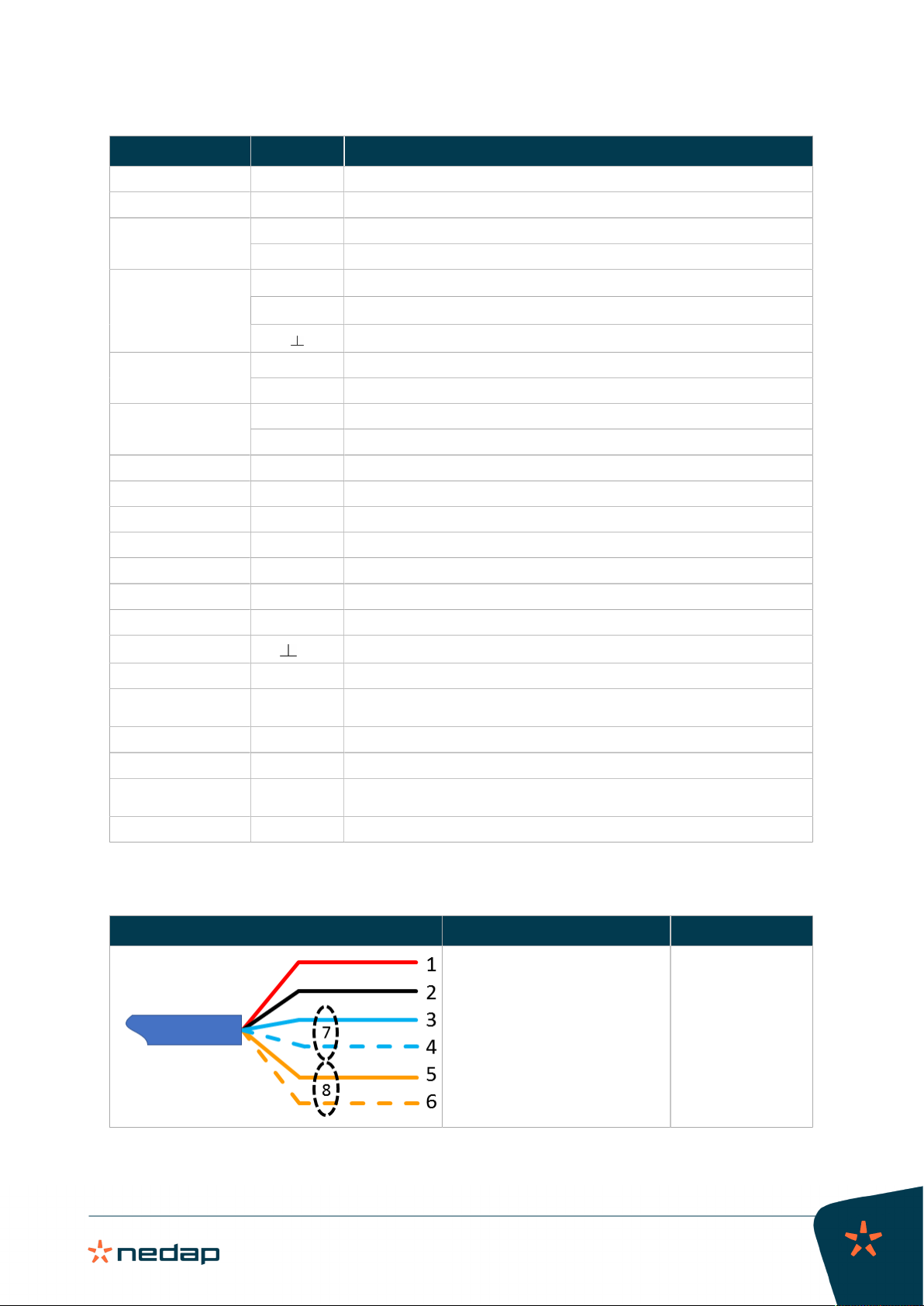
Velos CAN cable
Velos CAN cable Wiring Wire color
1. Power +25 Vdc
2. Power –
3. CAN High
4. CAN Low
5. HF synchronization
6. HF synchronization
7. Shield communication wires
8. Shield synchronization wires
1. Red
2. Black
3. Blue
4. Blue/white
5. Orange
6. Orange/white
7. Blank
8. Blank

VP1007-B / Installation manual
Version 01.000 / November 2020 / EN
9
Livestock Management
Caution
• The maximum number of V-packs that can be installed per CAN channel of the VPU depends on the
power consumption.
•.The maximum CAN cable length between the VPU and the last V-pack is 80 m (262 ft) with 1.5 mm2
(0.0023 in.2) cable and 100 m (328 ft) with 2.0 mm2 (0.0031 in.2) cable.
3.3.1 Wiring diagram VP1007-B
Figure1:Wiring diagram VP1007-B example
1. Velos CAN cable OUT (to next V-pack) 5. Antenna
2. Velos CAN cable IN (from VPU or previous V-pack) 6. Signal light
3. Switch Wiring colors: see Wiring color coding (page 28)
4. Feed motor
1. Install all wiring according to the VP1007-B wiring diagram. An example of a VP1007-B wiring diagram is
shown in Figure 1 (page 9).
If the VP1007-B is part of a complete Nedap system, use the installation manual of this system. The
installation manual can be obtained from your dealer or on our Business portal: http://www.nedap.com/
livestockmanagement-portal.
2. The SYNC connector is used for the synchronization of the ISO identification between more than one ISO
transceiver, such as the VP1007-B:
– The SYNC connection is mandatory when using the ISO mode of the VP1007-B
– When using FDX only it is not necessary to connect the synchronization cable.

VP1007-B / Installation manual
Version 01.000 / November 2020 / EN
10
Livestock Management
– Use a 2-conductor cable to connect the SYNC connectors of two or more VP1007-B transceivers
together.
The cable type is not critical, a twin lead or coaxial cable can be used. Also the connection is not
sensitive for polarization (+ and - are interchangeable).
3. Preferably, use ferrules to connect the wires. These ferrules are not supplied.

VP1007-B / Installation manual
Version 01.000 / November 2020 / EN
11
Livestock Management
4 Configuration
4.1 Configure the VP1007-B
Caution
Before configuring the VP1007-B, the system must be fully mounted and all cabling must be installed and
checked.
Some settings of the VP1007-B must be set prior to use.
1. Power up and check the LED indicators (see Power up check).
2. Set the required address (see Address setting).
Power up check
1. Power up the VPU.
2. Check if the VP1007-B has power after power up. The "Power", "Vi" and "Vo" LEDs must light up green.
3. Check if the LED "LAST" is green at the last V-pack on the CAN bus
4. When the LEDs are green, continue with address setting.
Caution
If the output LEDs are red (flashing), there is an output error. Go to It > dE in the display menu to reset all
errors.
The LED indicators are explained in VP1007-B reader LED indicators (page 25).
Address setting
The parameters and use of the VP1007-B are described in VP1007-B reader menu overview (page 26).
Each V-pack connected to the same VPU requires a unique logic address. Set the logic address of the VP1007-B
either manually or in Velos:
1. Set the logic address of the VP1007-B manually:
a. Go to parameter Ad > dA in the VP1007-B menu to read the logic address of the VP1007-B.
The default logic address of the VP1007-B is 01.
Caution
When the logic address is not a unique number, the logic address will blink in the display.
b. Go to parameter Ad > SA to set the logic address of the VP1007-B reader to a unique number when
multiple V-packs are connected to the same VPU.

VP1007-B / Installation manual
Version 01.000 / November 2020 / EN
12
Livestock Management
The available address range is 01 – 99.
c. To leave the menu, push and hold down the button until the display goes blank.
2. Set the logic address of the VP1007-B in Velos:
a. In Velos, go to Settings > Devices - V-packs.
b. Select the correct VPU in the drop-down list.
A list with all V-packs connected to the VPU is shown. The Address column shows the logic addresses of
the V-packs.
c. Find the VP1007-B in the list and check the logic address.
The default logic address of the VP1007-B is 01.
d. If necessary, click on the logic address and change it to a unique number. Click Ok to save the change.
Caution
V-packs with the same logic address are indicated with a red exclamation mark icon.
e. Click on Submit to save all changes.
4.2 Check for firmware updates
Caution
The VPUs and V-packs are never updated automatically by the VPU.
Update via the VPU
When the VPU or V-pack is connected with a computer, the firmware can be updated using the Nedap Velos
software:
1. In Velos, go to Maintenance > Devices - V-packs.
2. Select the correct VPU in the drop-down list.
A list with all V-packs connected to the VPU is shown. The Firmware column shows if an update is available.
3. Select the V-pack(s) that must be updated.
4. Click on Actions > Update.
5. Click on I agree to confirm.
VP1007-B / Installation manual
Version 01.000 / November 2020 / EN
13
Livestock Management
5 Commissioning
Caution
Before commissioning and handing over the system to the user, the installer must perform several checks
and tests to verify that the system functions flawlessly. Encountered issues and problems must be solved
first.
5.1 Testing inputs and outputs
The inputs and outputs of the VP1007-B can be tested with three tests:
1. Input/output test for Nedap feed motors.
2. Output test to check connected equipment like lights, valves or relays.
3. Input test to check connected equipment like switches and sensors.
The tests are performed using the menu options described in VP1007-B reader menu overview (page 26)
Feed motor test
The feed motor test is a combination of an input and output test.
1. Go to It > o1 to test the feed motor on the connector I/O 1.
When the test is finished, the test results are shown as a code on the display (blinking).
Code on the
display
Description motor test results
00 Motor run ok
01 Output already in use
02 No motor current measured
03 No input signal seen
06 Motor current too high for too long
08 Current still measured after test has stopped
09 Output voltage is stopped due to motor safeguard function
10 Output already in use
12 Motor current too low while running
13 Previous motor command finished, output still active
a. When the test result is not OK (higher than 00): Fix the problem and go to It > dE to reset the error.
2. If applicable, repeat step 1 for option o2, o3, o4 or o5 to test feed motors on connector I/O 2, I/O 3, I/O 4 or
I/O 5.
Output test
The output test is used to test connected equipment like light, valves or relay on the output connectors.
1. Go to It > L1 to test the connected equipment on output 1.
The output is switched on.
2. Check if the green LED of the output is on.
A red blinking LED indicates an output error.
3. Go to It > dE to reset the output errors.
4. Check if the connected equipment is activated.
VP1007-B / Installation manual
Version 01.000 / November 2020 / EN
14
Livestock Management
If not, check the wiring.
5. Press the button on the display to stop the test.
The output is switched off.
6. Repeat step 1 for parameter L2 to L5 to test equipment on output 2 to 5.
Input test
The input test is used to test connected equipment like switches and sensors on the input connectors.
1. Go to It > i1 to test the connected equipment on input (I) 1.
The input is read.
2. Check if the green LED of the input is on or off.
3. Switch the connected equipment on and off and check the values in the display.
The on and off setting must show a unique value (0 or 1).
When the VP1007-B is part of a complete Nedap system, the meaning of the input values (open or
closed) depends on the settings of the behavior component of the Nedap system.
4. Press the button on the display to stop the test.
5. Repeat step 1 for parameter i2 to i5 to test equipment on input (I) 2 to 5.
5.2 Antenna tuning
After the first time power up, the antenna tuning must be checked.
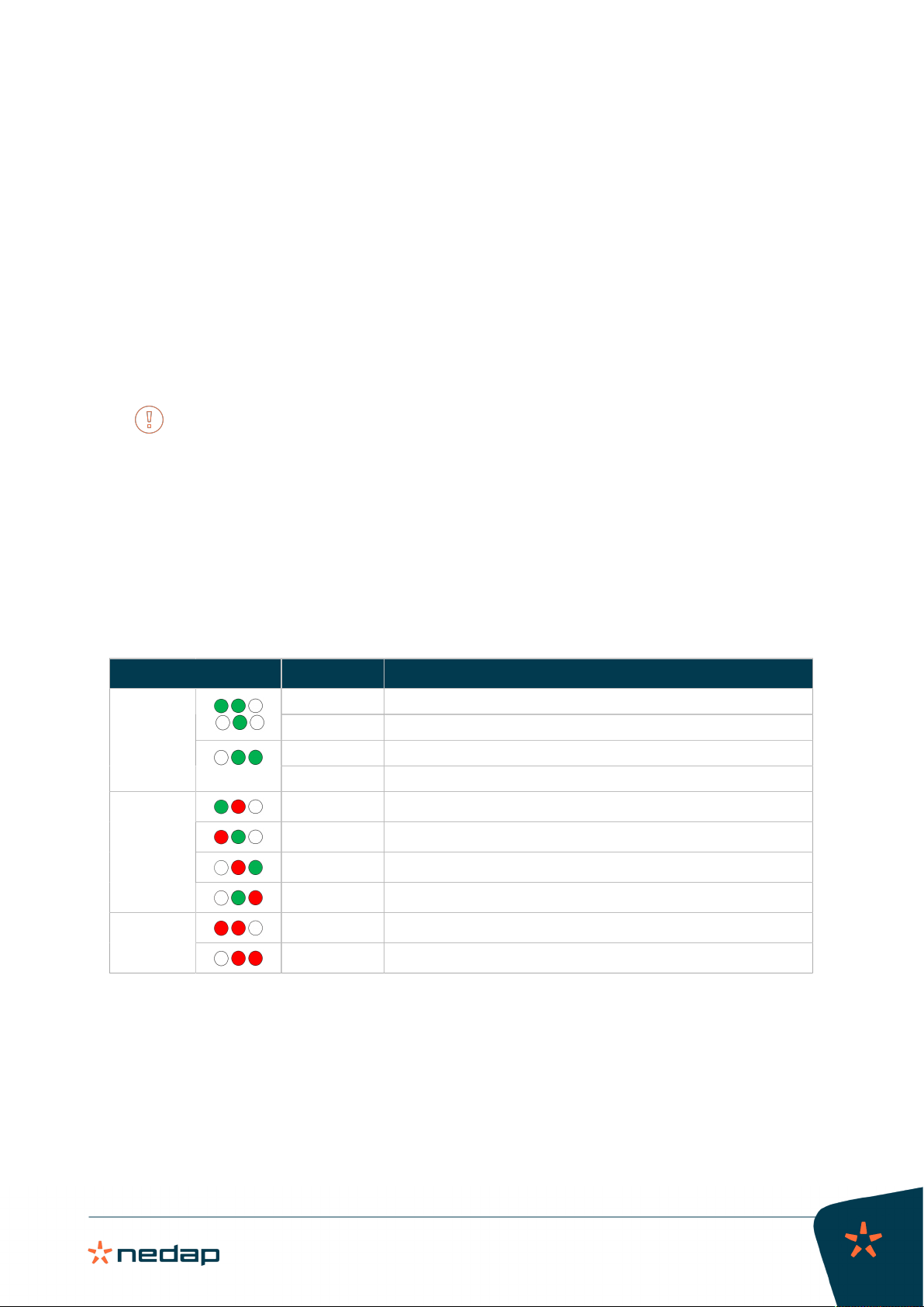
1. Check the TUNING LED and follow the instructions in the table (see also VP1007-B reader LED indicators
(page 25)):
Tuning LEDs Description Action
On Antenna 1 tuned correctly.
Blinking Antenna 1 identified tag.
On Antenna 2 tuned correctly.
Green
Blinking Antenna 2 identified tag.
Red on Antenna 1 not tuned correctly (turn left).
Red on Antenna 1 not tuned correctly (turn right).
Red on Antenna 2 not tuned correctly (turn right).
Various
Red on Antenna 2 not tuned correctly (turn left).
Red blinking Antenna 1 not connected or low antenna signal.
Red
Red blinking Antenna 2 not connected or low antenna signal.
5.3 Antenna adjustment
The Antenna Power (AP) and Antenna Squelch (AS) can be adjusted manually to optimize the detection of the
animal tags. The Adjust Antenna (AA) option can be used to manually tune the antenna.
The tests described in this section can be activated using the menu options described in VP1007-B reader menu
overview (page 26).
VP1007-B / Installation manual
Version 01.000 / November 2020 / EN
15
Livestock Management
Antenna power (AP)
1. Go to HF > H1 or H2 > AP in the menu to check the antenna power setting.
The default antenna power level is 99 (maximum value).
2. If necessary, adjust the setting of the antenna power AP.
Decreasing the antenna power level will reduce the reading distance of the antenna.
Increasing the antenna power level will increase the reading distance of the antenna, but the reading
distance is also dependent on conditions like external noise, tag quality and antenna configuration.
Antenna squelch (AS)
With Antenna squelch you can set a threshold for the ID level of an EID tag. There is a relation between ID
strength (RSSI) of a tag and the squelch level, and both values range from 0 to 99. Tags read with an RSSI value
lower than the squelch level will not be identified.
RSSI: The Received Signal Strength Indication is an indication of the signal strength received by the receiver.
The higher the RSSI value, the stronger the signal.
Squelch: The traditional squelch circuit is an audio switch controlled by the radio signal level using a fixed or
manually adjustable threshold (level). When the received signal strength falls below this, the receiver is muted.
When the VP1007-B reads the tag with an RSSI level below this threshold, the tag will not be read.
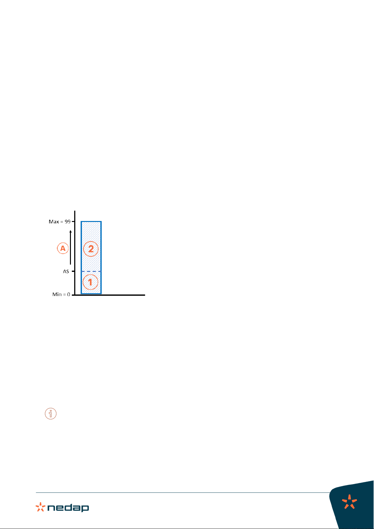
Figure2:Antenna squelch (AS) diagram
1. Received tag numbers are not transferred. A. Antenna Squelch (0 to 99%)
2. Received tag numbers are transferred. AS. Antenna Squelch setting (between 0% and 99%)
1. Go to HF > H1 or H2 > AS in the menu to check the antenna squelch setting.
The default antenna squelch value is 0% (most sensitive setting). At the lowest value there is no threshold
and all received tag data will be identified.
2. If necessary, adjust the antenna squelch value AS to set the correct threshold.
The maximum value is 99%. At this value no received tag data will be identified.
Antenna tuning with option "AA"
With the option Adjust Antenna (AA), you can follow the antenna tuning on the display of the VP1007-B.
The antenna can also be tuned using the TUNING LED on the display (see Tune the antenna).
1. Go to HF > H1 or H2 > AA in the menu to check the antenna tuning setting.
A value will appear on the display. The highest display value is the optimum adjustment.
2. Turn the antenna trimmer slowly.
The display value will change.
3. If the value decreases, turn the antenna trimmer the other way.

VP1007-B / Installation manual
Version 01.000 / November 2020 / EN
16
Livestock Management
4. Turn the antenna trimmer until the highest value is found.
Antenna reading distance
The antenna squelch and antenna power settings can be used to adjust the reading distance of the antenna for
an optimal detection of the animal tags:
1. Check if the antenna is set up correctly:
a. Check that the antenna is tuned correctly: see Antenna tuning with option "AA".
b. Check that the antenna power (AP) is set to the desired level (usually 99): see Antenna power (AP) (page
15).
Increase the antenna squelch when the antenna field interferes with other transmitting fields or
metal frameworks in the barn. If this is not sufficient, reduce the antenna power.
2. Check the maximum reading distance of the antenna with an EID tag (e.g. 120 cm for a neck tag in a walk
through antenna).
a. Move the tag to and from the antenna and use one of the following options to determine the maximum
distance for tag identification:
1. Check the TUNING/ID LED on the VP1007-B (see VP1007-B reader LED indicators (page 25)).
2. Go to HF > H1 or H2 > AS > id and check if the last two digits of the tag ID appear in the display.
Figure3:Antenna reading distance adjustment
1. Maximum before adjustment (e.g. 120 cm) 2. Maximum after adjustment (e.g. 80 cm)
3. Put the tag in the antenna field at the desired maximum reading distance (e.g. 80 cm) and read the RSSI
value:
a. FDX: Go to HF > H1 or H2 > AS > dF and note down the value (e.g. 60).
b. HDX: Go to HF > H1 or H2 > AS > dH and note down the value (e.g. 60).
4. Set the squelch value:
a. FDX: Go to HF > H1 or H2 > AS > SF and set the value noted in step 3a.
b. HDX: Go to HF > H1 or H2 > AS > SH and set the value noted in step 3b.
5. Repeat step 2. The maximum reading distance of the antenna should now be found at the desired distance
of step 3 (e.g. 80 cm).
5.4 Identification tests
The tests are performed using the parameters described in VP1007-B reader menu overview (page 26).
Tag identification
When a tag is detected by the antenna of the VP1007-B, the green TUNING/ID LED will automatically blink. The
identification (id) test can be used to identify the tag number.
1. When the green TUNING/ID LED blinks, go to It > id on the display.
The last two digits of the tag number are shown.

VP1007-B / Installation manual
Version 01.000 / November 2020 / EN
17
Livestock Management
FDX/HDX signal strength indication
The signal strength received by the reader of the VP1007-B can be tested. The FDX (dF) and HDX (dH) signals
are tested separately.
1. FDX test:
a. Go to HF > AS > dF on the display.
b. Press the button until the display starts to blink.
A value (0 - 99) will appear on the display.
c. Move an FDX tag slowly into the antenna field.
The display value will normally increase when getting closer to the antenna. If there is already a high
value when the tag is not in the antenna field, this is an indication that an external source is causing
noise (see Troubleshooting).
2. HDX test:
a. Go to HF > AS > dH on the display.
b. Press the button until the display starts to blink.
A value (0 - 99) will appear on the display.
c. Move an HDX tag slowly into the antenna field.
The display value will normally increase when getting closer to the antenna. If there is already a high
value when the tag is not in the antenna field, this is an indication that an external source is causing
noise (see Troubleshooting).
For the VPU or V-pack with an ethernet connection, the RSSI values are shown on the Overview page of the
web interface.
VP1007-B / Installation manual
Version 01.000 / November 2020 / EN
18
Livestock Management
6 Troubleshooting
Errors and malfunctioning of the VP1007-B are indicated by the indicator LEDs or codes on the display.
Indicator LED
Indicator LEDs are normally green (except the blue Status LED) or switched off. A red or orange indicator LED
usually means there is something not functioning correctly. See VP1007-B reader LED indicators (page 25) for
the explanation of the various colors.
Display code
Codes on the display are normally controlled by the VPU. The error will be indicated in the Velos web interface.
If the VP1007-B is part of a complete Nedap system, see the Troubleshooting section in the installation
manual of this system. The installation manual can be obtained from your dealer or on our Business portal:
http://www.nedap.com/livestockmanagement-portal.
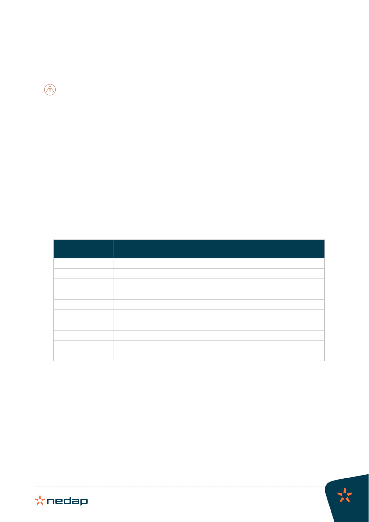
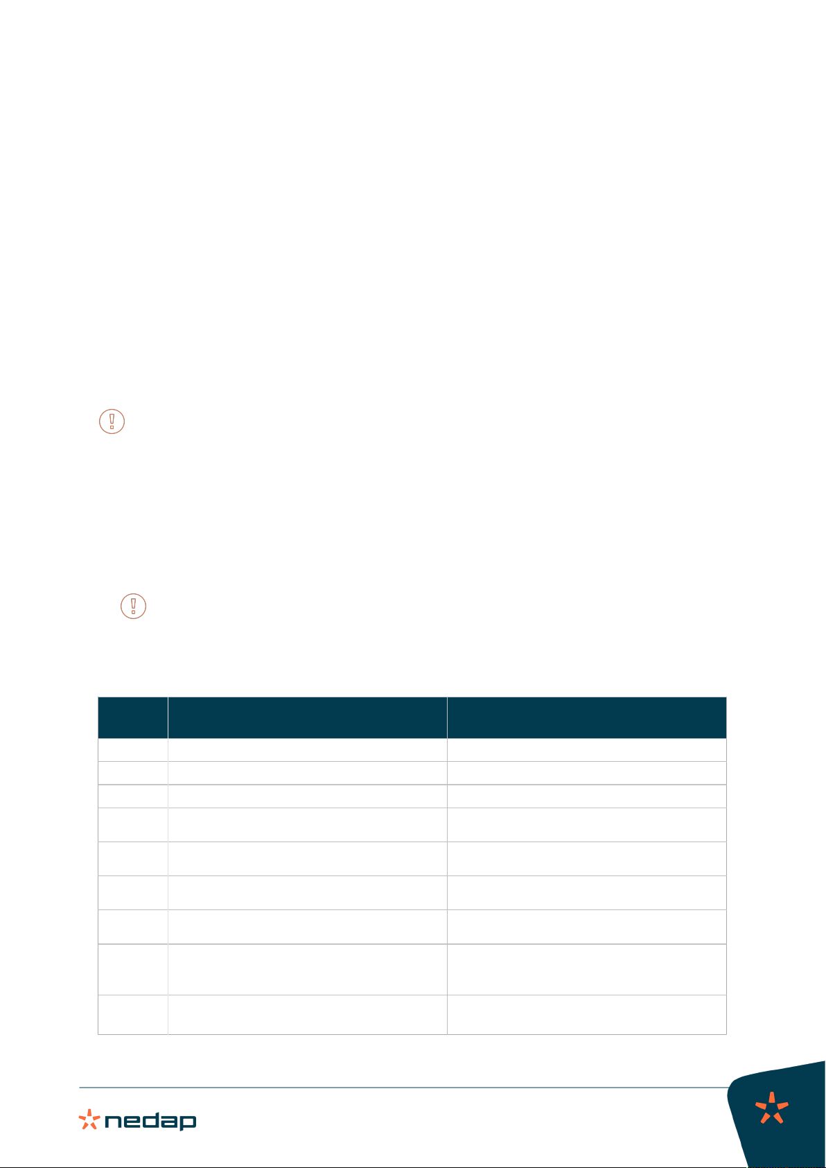
Error codes shown with menu option "dE"
Actual error codes can be displayed with menu option dE:
1. Select option dE on the display (see VP1007-B reader menu overview (page 26)).
The error code will be displayed.
Multiple error codes will be displayed one after another with a short gap between each code.
2. Press the button to clear the error.
3. If the error code is not cleared, the error could not be solved automatically. Try to solve the error.
Error
code
Description Possible solution(s)
00 No errors No action
03 Power to outputs turned off (high side) Test outputs one by one via it menu option
04 Power to outputs turned off (low side) Test outputs one by one via it menu option
09 Output 1: output error. Possibly caused by error 01
to 08.
Check connected device on output 1
10 Output 2: output error. Possibly caused by error 01
to 08.
Check connected device on output 2
11 Output 3: output error. Possibly caused by error 01
to 08.
Check connected device on output 3
12 Output 4: output error. Possibly caused by error 01
to 08.
Check connected device on output 4
13 Current too high (> 8 A) to next V-packs: Power to
next V-pack switched off
• Disconnect all next V-packs
• Reconnect next V-packs one by one and check
Vi LED (green)
17 CAN bus high voltage (> 10 V): CAN terminator
shut off
• Check CAN cable for damages or shortcuts
• Check connectors
Table of contents
Other Nedap RFID System manuals

Nedap
Nedap PROX-BOOSTER 2G User manual

Nedap
Nedap uPASS TARGET User manual

Nedap
Nedap TRANSIT Entry User manual

Nedap
Nedap ANPR LUMO User manual

Nedap
Nedap Transit Ultimate User manual

Nedap
Nedap TRANSIT User manual

Nedap
Nedap TRANSIT Entry User manual

Nedap
Nedap uPASS REACH User manual

Nedap
Nedap uPASS Access User manual

Nedap
Nedap MidRanger + Antenna Set User manual


