bluefin PUPUSC-330SU-R Instruction manual

PUPUSC-330SU-R
Installation, Operation, &
Maintenance Manual
Submersible Sump Pumps
PUPUSC-330SU-R

Tools:Recommended
•Pressurized Fittings
•Pipe fittings
•Check Valve
•Concrete
•Trowel
•Corrugated Pipe
•PVC Pipe
•Gravel
•Wire Ties
•Sump Basin
•Flexible connector
•GateValve
•PVC elbow
•Thread Tape
•PVC Purple Primer
•PVC Cement
•1/3HP Submersible Cast Iron Sump Pump x1
Contents:
Before getting started, ensure the package contains the following components:
Welcome Guide •English
3
Recommended Supplies

Part List
Parts Description Qty
A
B
C
D
E
F
G
H
I
J
K
Float rod
Circlip
Circlip for shaft
Volute
Bolts
Mechanical seal
Float
Motor
Float holder
Handle
Impeller
x1
x1
x1
x1
x1
x1
x1
x1
x1
x1
x5
4
B
C
D
A
E
F
H
I
J
K
G

IMPORTANT SAFEGUARDS
Read these instructions carefully and retain them for future use. If this
product is passed to a third party, then these instructions must be included.
Before First Use
•Check for transport damage.
Before beginning assembly of product, make sure all parts are present. Compare
parts with package contents list. If any part is missing or damaged, do not attempt
to assemble the product.
Estimated Assembly Time (New installation): 30 minutes (or longer if installing
new sump pit).
Always use handle to lift pump. Never use power cord to lift
pump. To avoid skin burns, unplug and allow timefor the pump to cool after
periods of extended use.
Materials Required for Assembly (not included): Flexible connector, Check valve,
GateValve,PVC pipe, PVC elbow, Thread Tape, PVC Purple Primer, and PVC Cement
Tools Required for Assembly (not included): Wrench, Phillips screwdriver
Risk of suffocation! Keep any packaging materials away
from children – these materials are a potential source of danger,
e.g. suffocation.
DANGER
When using the product, basic safety precautions should always be followed to reduce
the risk of injury including the following:
•Connect the pump DIRECTLY to a grounded, GFCI outlet.
Always disconnect the pump from its power source before installing,
inspecting, maintaining, or repairing.
Do not stand in water when the pump is connected.
•
Do not disassemble the motor housing. The motor has NO repairable internal parts,
and disassembling may cause oil leakage or dangerous electrical wiring issues.
•
Do not allow children to operate tool and keep children away from the work area.
•
Always use handle to lift pump. Never use power cord to lift pump. To
avoid skin burns, unplug and allow time for the pump to cool after periods of extended
use.
•
5
WARNING
WARNING

6
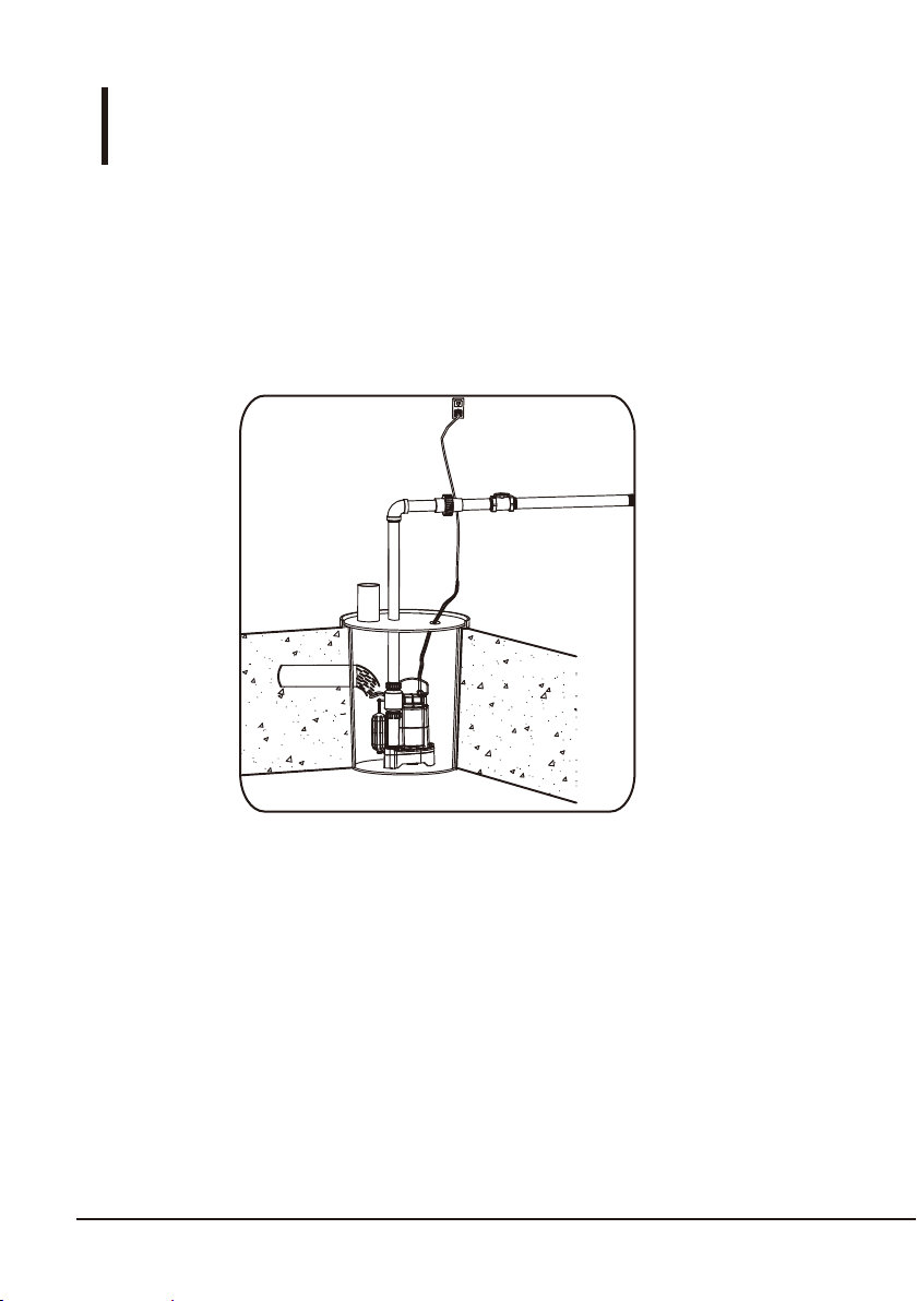
Installation
Step 1:
If using a basin, place the pump directly on the bottom of the basin. To prevent
damage set the pump on a solid, level surface. Do not place pump directly on
clay, earth, gravel or sand. A brick or block must be installed under the pump
to provide a solid base.
•
This installation must be in accordance with the National Electric
Code and all applicable local codes and ordinances.
NOTICE
Inlet Pipe
Sump Basin
at least 14”diameter
at least 22” deep

7
Installation
Step 2:
Connectinga discharge pipe to the pump. Wrap the threads of the discharge
pipe with a 1/8” air bleed hole (2) with thread sealant tape.
Attach the discharge pipe (2) to the discharge of the pump (1).
•
•
Install discharge plumbing according to local, regional and state
codes. Rigid PVC pipe is required. Do not use flexible hosing in
a permanent application. Install a check valve (required) to
preventback-flow.
NOTICE
2
1
Connecting a discharge pipe to the pump. Wrap the threads of the discharge pipe
with a 1/8" air bleed hole (2) with thread sealant tape.
Connecting the discharge pipe to the pump: Wrap the threads of the discharge
pipe with a 1/8" air bleed hole (2) with thread sealant tape.
prevent backflow.

Installation
8
Step 3:
Placing the pump in a basin and connecting the check valve: connect the discharge
pipe (1) to the elbow (2), union(3),check valve(4), and gate valve(5).
•
Position pump so the switch is away from the inlet, so switch is clear from
incoming water. Verify the switch has at least 1 in. clearance to the side
wall of the basin and is free to move throughout its movement. If optional
control device or float is used, follow mounting instruction supplied with
device or float.
NOTICE
Install a gate valve or ball valve if required by local, regional or state code.NOTICE
3
4
5
2
1
9
Connecting power: Secure power supply cord to discharge pipe using cable or
zip ties to prevent possible switch entanglement. Connect pump power supply
cord to a ground fault circuit interrupter (GFCI) receptacle.
•
Installation
Step 4:
Operating the pump: Fill the basin/pit with water,the pump will start when the
water level has reached the switch-on level. The pump will stop when the water
level has reached the switch-off level.
•
Step 5:
Operating the pump: Fill the basin/pit with water. The pump will start when the
water level has reached the switch-on level. The pump will stop when the water
level has reached the switch-off level.

10
SAFETY INFORMATION
CAUTION
This pump is designed for home sump applications. The pump is equipped with a 3-prong
grounding-type power cord. The ball bearings on the motor shafts never need to be lubricated.
This pump has not been tested or approved for use in swimming pools or in salt-water marine
areas. It is also not engineered to be run continuously as a “fountain” or “waterfall” pump.
Because this pump has an oil-filled motor, it should NOT be used in water containing fish.
Pump only water with this pump. For safety, the pump motor has an automatic resetting
thermal protector that automatically will turn off the pump if it becomes too hot. Overuse of
this feature will damage the pump and will void the warranty. Once the thermal protector
detects that the pump has cooled to a safe temperature, it will allow the pump to operate
normally. If the pump is plugged in, it may restart unexpectedly.
•
This pump is made of high-strength, corrosion-resistant materials. It will provide trouble-free
service for a long time when properly installed, maintained, and used. However, inadequate
electrical power to the pump, dirt, or blockage by ice or debris may cause the pump to fail,
eventually bringing about additional water damage. To minimize the potential for water
damage due to pump failure, please carefully read the manual and follow the instructions
regarding common pump problems and remedies.
•
•
Installation
Verify the switch is operating without any obstruction from the pump, piping and basin.15.
Fill the basin/pit with water again. While the pump is draining the basin/pit, verify the
discharge pipe is carrying the water to a point at least 3 ft. away from the foundation.
the pipe must be positioned in a downward slope away from the foundation, so any
remaining water will drain away and not freeze.
•
Step 6:
Secure the basin cover and gasket to the basin to prevent debris from falling into the basin,
prevent personal injury, and to contain gases and/or odors.
•
Step 7:
Verify the switch is operating without any obstruction from the pump, piping and basin.
Fill the basin/pit with water again. While the pump is draining the basin/pit, verify the
discharge pipe is carrying the water to a point at least 3 ft. away from the foundation.
The pipe must be positioned in a downward slope away from the foundation, so any
remaining water will drain away and not freeze.

11
ADDITIONAL SAFETY PRECAUTIONS
Know the pump applications, limitations, and potential hazards.
•
Make certain the electrical power source is adequate for the requirements of the pump.
•
ALWAYS disconnect the power to the pump and drain all water from the system before
servicing.
•
Secure the pump on a solid base to keep the pump vertical and above mud and sand
during operation to maximize pumping efficiency and prevent clogging and premature
pump failure.
•
Secure the discharge hose before starting the pump. Pump torque may cause an unsecured
discharge hose to “whip”, possibly causing personal injury and/or property damage.
•
Before using the pump, check hose for holes or excess wear, which could cause leaks,
and be sure hose is not kinked or making sharp angles. A straight hose allows the pump to
move the greatest amount of water quickly.
•
Check that all hoses connections are tight to minimize leaks.
•
Connect the pump DIRECTLY to a grounded, GFCI outlet.
•
Make certain the electrical circuit to the pump is protected by a 10-amp or larger fuse or
circuit breaker.
•
Periodically inspect pump and system components, to be sure pump inlets are free of
mud,sand and debris. DISCONNECT PUMP FROM THE POWER SUPPLY BEFORE
INSPECTING.
•
Wear safety glasses at all times when working with pumps.
•
Protect the electrical cord from sharp objects, hot surfaces, oil, and chemicals. Avoid
kinking the cord. Do not use damaged or worn cords.
•
Follow all electrical and safety codes, particularly the National Electrical Code (NEC) and
in the workplace, the Occupational Safety and Health Act (OSHA).
•
This unit is designed only for use on 115 volts (single phase), 60 Hz, and is equipped with
an approved 3-conductor cord and 3-prong grounded plug. DO NOT REMOVE THE
GROUND PIN UNDER ANY CIRCUMSTANCES. The 3-prong plug must be directly
inserted into a properly installed and grounded 3-prong, grounding-type receptacle.
Do not use pump with a 2-prong wall outlet. Replace the 2-prong outlet with a properly
grounded 3-prong receptacle (a GFCI outlet) installed in accordance with the National
Electrical Code and local codes and ordinances. All wiring should be performed by a
qualified electrician.
•
Extension cords may not deliver sufficient voltage to the pump motor. Extension cords
present a life-threatening safety hazard if the insulation becomes damaged or the
connection ends fall into water.
•
CAUTION

12
Cleaning and Maintenance
TROUBLESHOOTING
•The pump should be inspected 3-4 times per year for pump movement or buildup of
debris on the switch or float. Reposition pump if it has moved. Remove any debris that
could interfere with the operation of the switch. Lack of proper routine maintenance
will void warranty.
•Make sure the pump is plugged in to a working ground fault circuit interrupter (GFCI)
outlet and the cord is in good shape. In damp areas, GFCI breakers may trip,
effectively shutting off the sump pump. Check in on your sump pump and reset the
GFCI if necessary.
•Ensure the pump itself is standing upright. Vibrations during operation can cause it to
fall or tilt onto one side. This can jam the float arm so it can’t activate the pump.
Do not disassemble the motor housing. This motor has NO repairable internal parts, and
disassembling may cause an oil leak or dangerous electrical wiring issues.
•
WARNING
Possible Cause
Problem Corrective Action
Pump does
not start or
run
The pump
will not
prime or
retain prime
after
operating
1. Blown fuse
2. Tripped breaker.
3. Plug disconnected.
4. Corroded plug.
5. Thermal overload.
6. Motor failed.
7. Float switch obstructed.
8. Float switch failed.
1. Replace fuse.
2. Reset breaker.
3. Secure plug.
4. Clean plug prongs.
5. Unplug for 30 minutes, then plug in.
6. Make sure the float switch has room
to move and is not getting caught
on anything. Make sure your pit is at
least 14 in. wide.
7. Purchase a replacement float switch.
1. Clean screen.
2. Reassemble impeller.
1. Screen blocked.
2. Impeller loose on shaft.
3. Impeller broken.

13
Specifications
ASIN : B07SPYCNST
Property Specifications
Voltage
Horsepower
Amps
Maximum head height
Maximum flow (GPH)
Discharge size
Power cord length (ft.)
1/3 HP
6.2 A
115V / 60Hz
30.4' (9.3 m)
3680 U.S. GPH (13929 L/hr)
1-1/2"
10’ (3 m)
5’ (1.5 m)
3510 U.S. GPH
(13285 L/hr)
10’ (3 m)
3048 U.S. GPH
(11536 L/hr)
2472 U.S. GPH
(9356 L/hr)
1800 U.S. GPH
(6813 L/hr)
15’ (4.5 m) 20’ (6 m)
PERFORMANCE
PUPUSC-330SU-R
: PUPUSC-330SU-R
Table of contents
Other bluefin Water Pump manuals


