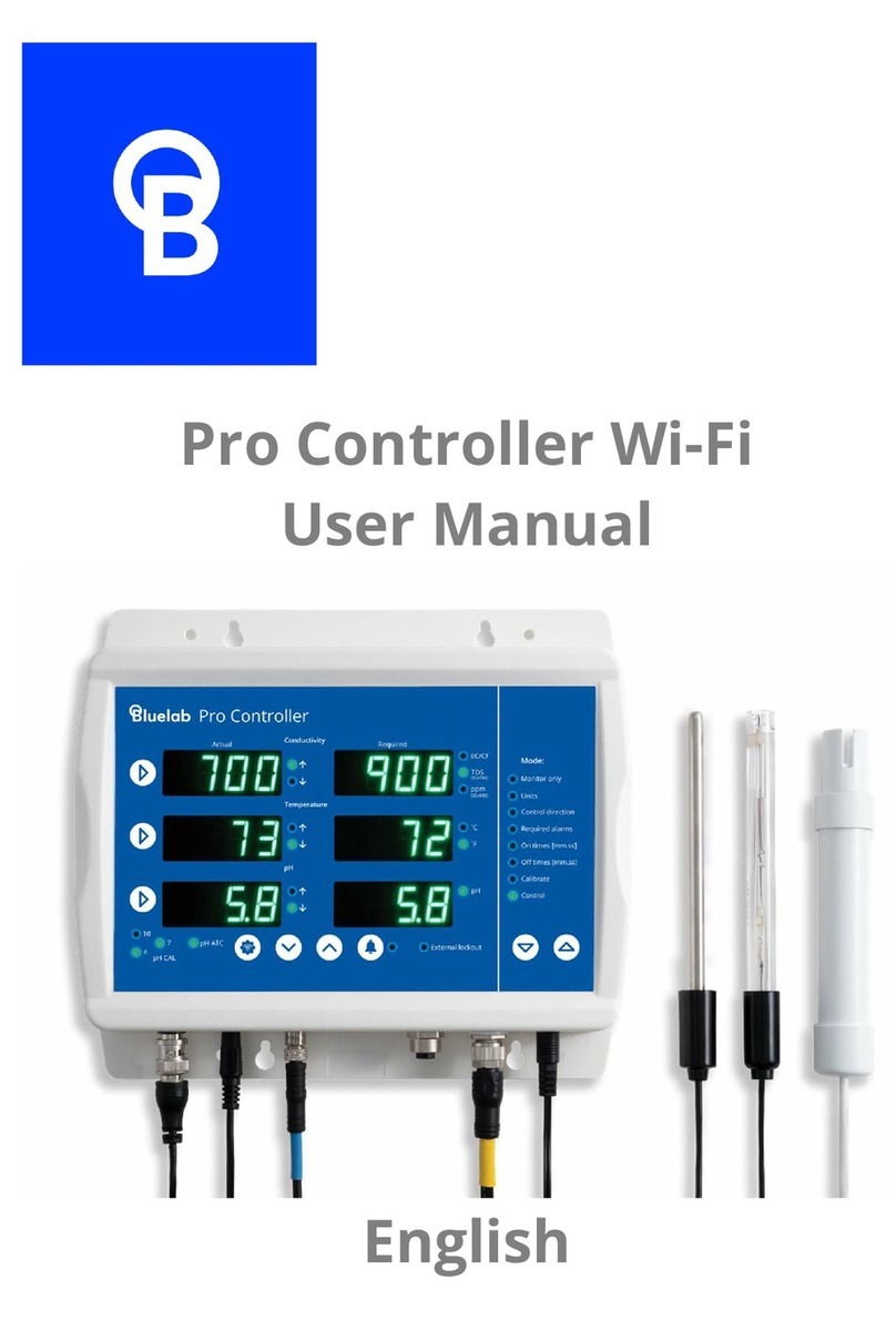
bluelab pH Controller Wi-Fi User manual

pH Controller Wi-Fi
User Manual
English

Contents
1.0 Introduction & Overview .............. 3
1.1 Features ........................................... 3
1.2 What’s in the box? .......................... 3
1.3 How it works ................................... 4
1.4 Terms (Glossary) ............................. 4
2.0 Bluelab pH Controller .................... 7
2.1 Bluelab pH Controller overview .... 7
2.2 Bluelab pH Controller display ....... 7
2.3 Connect the probes........................ 8
2.4 Power up ......................................... 8
2.5 Bluelab pH Controller Menu ......... 9
2.5.1 Set the mode ........................... 10
2.5.2 Set the required pH ................ 10
2.5.3 Alarms (optional) ..................... 11
2.5.4 Set the dosing direction – for
pH up or down solution ............. 11
2.5.5 Dosing OnTime and OffTime . 12
2.5.6 Pump Speed ............................ 12
2.5.7 Screen backlight and/or
contrast ........................................ 13
2.5.8 Number of calibration points 13
2.5.9 Display language ..................... 14
2.6 View current settings / status ..... 15
2.7 Factory settings ............................ 15
3.0 Installing the Bluelab pH
Controller ......................................... 16
3.1 Mounting the Bluelab pH
Controller ......................................... 16
3.2 Placement of the probes ............. 16
3.3 Set up inlet dosing tube ............... 17
3.4 Set up outlet dosing tube ............ 18
3.5 Pump override (Priming) ............. 18
4.0 Wi-Fi Connection (optional) ........ 19
4.1 Connect to Wi-Fi for the first time
.......................................................... 19
4.2 Connect to a different Wi-Fi
Network ........................................... 20
4.3 Enable / Disable Wi-Fi .................. 20
5.0 pH Calibration .............................. 21
5.1 How to perform a pH calibration 21
5.2 pH calibration Tips ....................... 24
6.0 Probe Care .................................... 25
6.1 Bluelab pH Probe care ................. 25
6.2 Cleaning the Bluelab pH Probe .. 27
6.3 Hydrating the pH probe .............. 28
7.0 Troubleshooting & FAQ ............... 29
7.1 Troubleshooting guide ................ 29
7.2 Frequently asked questions ........ 31
8.0 Specifications ............................... 32
8.1 Technical specifications ............... 32
8.2 pH adjuster compatibility for
tubing3.............................................. 33
9.0 Accessories & Warranty .............. 34
9.1 pH Probe replacement ................ 34
9.2 Probe Care Kits ............................. 34
9.3 Peristaltic Pump ............................ 34
9.4 Acid/Alkali Resistant Dosing Tube
with Connectors ............................... 34
9.5 pH Probe KCl Storage Solution .... 34
9.6 Bluelab limited warranty ............. 35
10. Get in touch .................................. 36

1.0 Introduction & Overview
1.1 Features
Built-in Wi-Fi (with option to disable)
Local and remote adjustment of
control
settings via Edenic by Bluelab software
Data logging capability (via Edenic by
Bluelab software)
Automatic
control
and
monitoring
of
system pH with reservoirs up to 2,000 US
Gallons
/
7
,
6
0
0
Litres
Flashing high and low alarms stop further
dosing
Dosing
lockouts
to
protect
from
over
-
dosing
Auto
resume
dosing
on
restart
after power
loss
Simple push button pH calibration with
on screen
instructions
Large, easy to read display
Easy
to
navigate
menu to
program
and
adjust settings
‘
Plant
-
safe’ green back lit LCD with
adjustable brightness and contrast
Water resistant, wall mount design
13
foot
(4
meter)
acid/alkaline
resistant
tubing
supplied
Replaceable double junction Bluelab pH
Probe
Replaceable peristaltic pump and tubing
Separate stainless steel Bluelab
Temperature Probe (for pH ATC)
International
power
supply
What is Plant Safe? Green lights are safe for continued growth during a plant’s
fruiting stage when hours of darkness are required.
What are Dosing Lockouts for? They are a built-in safety feature that stops pH
dosing if an error is detected in the system (see FAQs for more detail).
1.2 What’s in the box?
1x Bluelab pH Controller Wi-Fi
1x Universal Power supply 24 VDC 0.3 A output
1x pH Probe with 2 m (6') cable
1x Temperature probe with 2 m (6') cable
1x Acid resistant (PTFE) tubing 4 m (13')
2x Straight joiners (PVDF) 1/8"
4x Mounting screws
2x pH Calibration solution sachets

1.3 How it works
The Bluelab pH Controller continually monitors and controls the pH level of a solution.
It utilises a separate probe for temperature and pH to accurately measure changes in your
solution, and has a built-in 120ml per minute peristaltic pump.
1.4 Terms (Glossary)
Displayed pH
The current pH measured by the pH probe.
Required pH
The target pH the Bluelab pH Controller will maintain when in Control mode.
Dosing cycles
Automated control of pH is achieved by dosing. The Bluelab pH Controller does this
with a dosing cycle method that consists of an OnTime and an OffTime.
OnTime
The time that the pump runs for in each dosing cycle. As a guide, three dosing cycles
should change the reservoir by 0.1 pH points.
IMPORTANT
If the OnTime is too short, it is possible that the Bluelab pH Controller won’t be
able to dose enough to keep up with the changing pH levels, even if it doses
every dosing cycle.
If the OnTime is too long, the value is likely to overshoot; i.e. a single dose
changes the value so much it goes over the desired value.
OffTime
The delay time between each dose (or OnTime). This gives the system time to mix the
stock solution into the reservoir thoroughly, so the Bluelab pH Controller measures
the solution accurately. Start with a longer OffTime and reduce it over time.
IMPORTANT
If the OffTime is too short, the pH stock solution will not have been properly
mixed in the reservoir. The Bluelab pH Controller may dose again, which can
result in overshoot of the required value.
If the OffTime is too long, it is possible that the pH levels may change too much
between doses.

Mixing Time
How long it takes from adding the pH solution until the pH reading becomes stable.
Mixing times (and therefore the OffTime) can be reduced by installing mixing pumps,
air injection or other mechanical means of mixing into the reservoir. The mixing time
of the reservoir can be estimated by manually adding sufficient nutrient to
significantly shift the pH value, while timing how long it takes from adding the pH
solution, to when the pH reading becomes stable.
Dosing lockouts
Some conditions will cause the Bluelab pH Controller to stop controlling. These are
called dosing lockouts. The three types of Dosing lockouts are Measurement range
limits, Alarms, and Ineffective control lockout (each explained below).
Measurement range limits
Both of the measurement types (pH and temperature) have a measurement range
within which they can measure. pH for example, can be measured between 0.0 pH and
14.0 pH; temperature between 0 °C and 50 °C.
If values outside these limits are detected, the pH Controller will indicate that it is
under or over range by flashing the display and displaying “ur” or “or” in the affected
measurement type. Dosing will immediately stop.
Alarms
When alarms are turned on, and the Bluelab pH Controller senses that either pH is
beyond the set high or low alarm values, pH dosing will stop.
IMPORTANT
Alarms are not just warnings that values have shifted away from the required
value - they stop dosing. Be careful not to set alarm values which are too close to
the required values, as they may result in the Bluelab pH Controller going into
alarm because of small variations in measured values.
When the values return to within the limits of the set alarms, the alarm state
ceases, and after a 60 second countdown, the Bluelab pH Controller begins
controlling again, dosing as required. The alarm state can also be cancelled by
switching alarms off (via alarm in the menu or switching alarms off via Edenic).
After a 60 second countdown the Bluelab pH Controller will begin controlling
again.

Ineffective Control Lockout
The Bluelab pH Controller continually checks to ensure that dosing is having an effect.
It will go into lockout if 15 dosing cycles do not move the pH value by at least 0.1 pH in
the desired direction. This is called the ineffective control lockout, and is enabled by
default, but can be disabled via Edenic.
The Bluelab pH Controller will indicate it is in ineffective control lockout by flashing the
display and displaying ‘HELP Ineffective Control’.
IMPORTANT
The ineffective control lockout is useful to stop dosing if pH solution tanks have
emptied, or a hose has fallen out of a reservoir, for example.
However for a batch dosing system where fresh water is being added to the
reservoir at the same time as dosing is occurring, it may be better to disable this
feature.

2.0 Bluelab pH Controller
2.1 Bluelab pH Controller overview
2.2 Bluelab pH Controller display
D
isplay
Inlet tube
Enter button
Up
button
Down
button
Settings
button
pH probe BNC
connector
Temperature
probe input
Power input
pH calibration
button
Peristaltic pump
with cover
Outlet tube
Successful pH
calibration indicators
Reading display
pH controller status, menu
options or instructions
Reading display
Alarm is on
pH control
direction –
up OR down
Automatic
Temperature
Compensation (ATC)
if Temperature
Probe is connected

2.3 Connect the probes
It is recommended to test the Bluelab pH Controller prior to mounting. Attach both the
pH and Temperature probes to the controller, plug in the power adaptor, place probes
into solution and wait a few minutes for the readings to stabilise.
pH Probe
Line up the lugs of the BNC probe
connector with the receptacle on the
Bluelab pH Controller labelled ‘pH’.
Fasten securely by pushing the pH
probe connector on and twisting one
quarter turn.
Push connector Twist & attach
Temperature Probe
Fully insert the temperature probe
connector into the Bluelab pH
Controller receptacle marked ‘ATC’.
2.4 Power up
Select and connect the appropriate mains plug
adaptor for your region to the power supply
unit.
Connect the power adaptor into the Bluelab pH
Controller receptacle marked ‘PWR’.
Plug the power adaptor into a mains outlet and
switch it on. The Bluelab pH Controller will
complete a display test sequence.
The default setting, is ‘monitoring’ mode.
Note: pH calibration must be completed before
the first use, see section 5.0 to ensure pH
readings are accurate.
Temperature
probe connection
Attach power
adaptor

2.5 Bluelab pH Controller Menu
The ‘Settings’ button will take you into the menu.
To exit the menu, press ‘Settings’ again. Changes will not
be saved.
The ‘
∧
’ (up arrow) button allows you to move up the menu
items or increase a value shown.
The ‘∨’ (down arrow) button allows you to move down the
menu items or decrease a value shown.
To use the ‘Auto-repeat’ feature: Press and hold the ‘∧’ (up
arrow) or ‘∨’ (down arrow) button to scroll through
options. Release when you see the desired option or
value on the screen.
The ‘’ button allows you to select the desired option
shown on the display or save a chosen value.
The ‘CAL’ button is used to calibrate your pH probe. A
long press enters the calibration sequence.
Adjusting Settings
To adjust any of the settings, modes or alarms
1. Press the ‘settings’ button.
2. ‘∨’ or ‘∧’ to find the menu option required.
3. ‘’ to enter that menu item.
4. ‘∨’ or ‘∧’ to adjust the parameter.
5. ‘’ to save the change.
6. ‘Settings’ button to exit.
If you have adjusted a parameter and don’t want to save, you can let the menu
timeout or press the ‘settings’ button which will exit without saving.

2.5.1 Set the mode
The
Bluelab
pH
Controller
has
two
modes
of
operation
(monitor
and
control).
Monitor mode displays the current solution pH reading.
Control mode allows the pH controller to dose pH solution to the set values.
Dosing will NOT occur when:
The pH controller is in ‘monitor’ mode
The pH controller is in an alarm state
The pH controller is in ineffective lockout state.
The solution temperature is above 50 °C / 122 °F, or below 0 °C / 32 °F
To
set
‘monitor’
mode
(set by default)
:
1.
In the menu select
‘Mode’
,
press
‘
’
to enter.
2. Press ‘∨’ or ‘∧’ to select ‘monitor’
3. Press ‘ to save the mode.
To
set
‘control’
mode:
1.
In the menu select
‘Mode’
and press
‘’ to enter.
2. Press ‘∨’ or ‘∧’ to select ‘control’
3. Press ‘’ to save the mode.
The display will show a countdown before the
pump can start. This is: 15 sec when exiting the
menu with control mode enabled; 60 sec if power
off/on occurs.
2.5.2 Set the required pH
1.
S
elect
‘Set
pH’
and press
‘
’
to
enter.
2. Press ‘∨’ or ‘∧’ until the required pH
is shown in the main display.
3. Press ‘’ to save the value.
Note: If you have already set high and low
alarm values, you may see the values change
depending on the pH value being set

2.5.3 Alarms (optional)
The alarm function alerts you when the solution
deviates too far from the desired
pH. When an alarm condition is present, the pH value and the alarm symbol will
flash on the screen. This is an ‘alarm lockout’ state. All dosing will stop.
If the measurement changes back to within the limits you have chosen, the
flashing will stop and dosing will start.
To
set
the
‘High
Alarm’
value:
Use the menu
item
‘Alarm
High’
To
set
the
‘Low
Alarm’
value:
Use the menu item
‘Alarm
Low’
To
turn
the
alarm
on or off
:
Use the menu item
‘Alarm’
2.5.4 Set the dosing direction – for pH up or down solution
Use the menu
item
‘
Dos
e’
Select ‘Down/Acid’ for dosing acid (pH
down solution).
Select ‘Up/Alkali’ for dosing alkali (pH
up solution)

2.5.5 Dosing OnTime and OffTime
A
dosing
cycle
includes
the
OnTime
and
the
OffTime
that
the
peristaltic
pump doses
for. The arrow symbol on the display will flash during the dose cycle.
Adjustments for OnTime and OffTime will be required so that three dosing cycles
only change the pH value by 0.1 pH.
Start with a long ‘OffTime’ and adjust back as you go. The more thorough the
mixing in the tank, the shorter the ‘OffTime’ can be.
To
set
the
OnTime
value:
Use the menu item
‘OnTime’
‘OnTime’ the length of time pump will
dose for. From 1 to 60 seconds.
To
set
the
OffTime
value:
Use the menu item ‘
Off Time
’
.
OffTime’ the delay time between each
dose. This gives the system time to mix the
stock solution into the reservoir thoroughly,
so the Bluelab pH Controller measures the
solution accurately. From 1 to 60 minutes.
2.5.6 Pump Speed
To
change
the
pump speed:
Use the menu item ‘Pump Speed’
Can be set at 20%, 40%, 60%, 80% or 100%.
The default is 100%.
Note, the actual flow rate will not change
linear due to tubing size and viscosity of
liquid. Always test the flow rate to ensure
it takes at least three dosing cycles to
change your reservoir pH by 0.1.

2.5.7 Screen backlight and/or contrast
To
change
the
screen
backlight:
Use the menu item
‘
Backlight’
Can be set at 0%, 25%, 50%, 75% or 100%.
To change the screen contrast:
Use the menu item ‘Contrast’
Can be set between 0 and 30.
2.5.8 Number of calibration points
If you are calibrating to TWO solutions, remember:
If a reading below pH 7.0 is expected, use pH 7.0 and pH 4.0 calibration solutions.
If a reading above pH 7.0 is expected, use pH 7.0 and pH 10.0 calibration solutions.
You would require calibration in THREE solutions if:
Readings above and below pH 7.0 are expected, use pH 7.0, pH 4.0 then pH 10.0
calibration solutions. You will need to enable 3-point calibration in the settings
menu.
To
change
the
calibration point:
Use the
menu item ‘
2/3
p
oint
Cal’

2.5.9 Display language
Use the menu item
‘L
anguage
’

2.6 View current settings / status
Use
this
option
to view
your
programmed settings
at
any
time.
Press ‘∨’ or ‘∧’ while in ‘monitor’ or
‘control’ mode. The setting for each value
is displayed at the bottom of the screen.
The display will revert to displaying
‘Required pH’ if no button is pressed
after 1 minute.
2.7 Factory settings
The pH controller is set to the following values by default:
• Mode Monitor • Backlight 100% On
• Set pH 5.8 • Pump Speed 100
• Alarm On • Contrast 6
• HighAlarm 6.5 • 2/3 point Cal 2
• LowAlarm 5.6 • EarthLink Off
• Dose Up/Dn Down/Acid • Wi-Fi On
• OnTime 1 Sec • Language eng
• OffTime 10 Min • pH Calibration none
Note: ‘Pump’ runtime [HH:MM:SS] is the time the pump has dosed for. Product ‘RunTime’
[Hrs] is the duration of time the pH controller has been in use for. Pump runtime and
product runtime are never reset, even after pump replacement.
To restore the pH controller to the above factory settings at any stage:
Disconnect the power
Press and hold the ‘CAL’ button then reconnect the power.
When ‘Restored Factory Defaults’ is displayed on the screen, release the ‘cal button’.

3.0 Installing the Bluelab pH Controller
3.1 Mounting the Bluelab pH Controller
Select a suitable location that is:
Less than 5.65 feet / 2 meters from your reservoir.
The probes must be immersed in solution at all
times. Less than 4.9 feet / 1.5 meters from an
electrical mains outlet.
Less than 5.56 feet / 2 meters from pH Up or Down
solution. The inlet tube must reach the bottom of
the container.
At a suitable height to see the display and for easy
operation (recommend slightly below eye level
when standing).
NOTE: Avoid placing the pH controller where it can be
damaged by direct sunlight, water, nutrient salts or pH
adjuster.
Fix the fasteners through the desired
mounting holes
in the top and bottom of the case.
3.2 Placement of the probes
The tip of the Bluelab pH Probe must be submerged in the liquid for a
measurement to occur. It is optional to use the Bluelab Temperature Probe, but it
is required for automatic temperature compensation (ATC) to occur, or to enable
‘Earthlink’.
Do not pour concentrated nutrient solution or pH adjuster directly onto probes when
in the reservoir. Strong acids, alkali and nutrients damage the probes, trigger the
alarms (if on), cause the pump to accidentally dose or stop dosing, or interfer with
the control program.
For accuracy, ensure the probes are in an area where the reservoir/tank solution is
well mixed.
pH and temperature probes can be fully submerged in the solution.
1.
Remove the storage cap from the pH probe by
gripping the top of the cap and gently twisting
the base one rotation to loosen. Slide the
storage cap off the pH probe.
Mounting holes at top
Mounting holes at bottom

2.
Fit
the
(optional)
pH
probe
holder
to
the
stem
of
the pH probe using a gentle twisting motion.
3. Place the pH probe into the reservoir/tank and
push the suction cup onto the side of the
reservoir but far enough down so the pH probe
tip is always in the solution. This prevents
damage to the probe from any movement in the
reservoir/tank.
4. Place the temperature probe alongside the pH
probe.
3.3 Set up inlet dosing tube
To straighten tube:
Bend tube in the opposite direction and
straighten by running through closed fingers.
Insert one end of the dosing tube with
connector into the LEFT peristaltic pump tube.
This is the ‘inlet dosing tube’.
Ensure the inlet dosing tube will reach the
bottom of the pH stock solution container.
There also needs to be enough tube left for the
outlet dosing tube to go into the reservoir/tank.
Cut the inlet dosing tube to the desired
length. Use inlet tube cap supplied to place on
Bluelab Up or Down 500ml or 1 Liter bottles.
This will hold the tube in position. Insert the
inlet dosing tube through the hole in the cap
and pierce the induction seal on the bottle.
Inlet ‘’
arrow on
pump cover
Connector
Left pump
tube
Inlet dosing
tube
Dosing tube reaches
bottom of container
Inlet tube cap
pH stock
solution

3.4 Set up outlet dosing tube
Insert the remaining dosing tube with
connector into the RIGHT peristaltic pump
tube. This is the ‘outlet dosing tube’.
Cut the outlet dosing tube so that the tube
sits above the maximum solution level of
the reservoir/tank. The pH stock solution
must drip into the nutrient reservoir/tank.
Note: If the outlet dosing tube is immersed in
reservoir/tank solution, it could create a
syphon. This would cause the pH stock solution
to overflow.
3.5 Pump override (Priming)
‘Pump Ovride’ allows you to fill the inlet and outlet tubes with dosing solution
before first use (removing any air in the tubes), and to manually dose the tank if
required.
NOTE: If priming the pump, temporarily move the outlet dosing tube so it runs into
the pH stock solution container (if not already fixed in place). This will avoid adding
pH
stock
solution to your tank/reservoir unintentionally.
Use the menu item ‘
Pump
Ovrde’
1. Press ‘
∨
’ to manually operate the
pump.
2. Release the button to stop the pump
when you see the stock solution
begins to drip from the outlet dosing
tube.
CHANGING STOCK SOLUTION:
If you are changing from pH Up to pH Down, or vice
versa, you MUST flush the dosing tube with water FIRST to avoid a chemical
reaction in the tube.
Connector
Outlet ‘’ arrow
on pump cover
Right pump tube
Inlet dosing
tube
Outlet dosing
tube
Nutrient solution
reservoir / tank
pH stock
solution

4.0 Wi-Fi Connection (optional)
4.1 Connect to Wi-Fi for the first time
To connect the device to Wi
-
Fi, it is helpful to have the onboarding QR code
available for scanning. This can be found on the back of the device or on the
packaging.
Have the security code QR image handy.
Example
:
When first powered on, the pH Controller Wi-Fi automatically starts in Provisioning
mode. This allows Wi-Fi settings to be configured from a mobile device. Once the
pH controller has been connected to a Wi-Fi network it will no longer start in
Provisioning mode. If you need to connect to a new network, see section 4.2.
1.
Ensure Bluetooth is enabled on your mobile device and the Edenic app is
installed.
2. Open the Edenic app on your mobile device and log in.
3. Remove the pH Controller power cable for a few seconds then reconnect.
4. In the Edenic app, click the add device button in the bottom right.
5. Select scan a QR code.
6. Scan the QR code provided on the back of your pH Controller / packaging.
7. Enter a device name to help you recognise this pH controller Monitor.
8. Wi-Fi details – Click the view Wi-Fi networks to see available networks.
9. Select the Wi-Fi network you want to connect to.
10. Enter the Wi-Fi network password.
11. Select continue, your device will now be ready and connected.

4.2 Connect to a different Wi-Fi Network
To reprovision:
1.
Use the menu
item
‘Wi
-
Fi’
.
2. Press ‘’ to select ‘Provisioning’.
3. The security code is displayed
indicating that the device is ready to
accept new Wi-Fi settings.
4. Use the Edenic App on your mobile
to complete the setup for a new
network.
4.3 Enable / Disable Wi-Fi
By default, Wi
-
Fi is enabled. If you want to disable Wi
-
Fi follow these instructions:
1.
Use the menu item ‘Wi
-
Fi’.
2. If turned on, the status is shown
above the menu.
a. Conn – Wi-Fi is connected
b. Err1 – Wi-Fi not connected
c. Err2 – No internet available
d. Err3 – Edenic service not
reachable
e. Err4 – Time sync, please
wait.
3. Select ‘Data’ and ‘’ to enter Data
menu.
4. Select Off to disable Wi-Fi.
On to enable.
Table of contents
Other bluelab Controllers manuals
