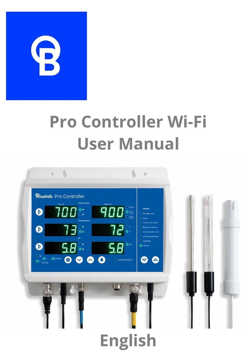
bluelab Dosetronic User manual

Solenoid Kit
i
i
c
c
c
d
o
o
s
e
e
troni
i
i
ic
c
English
Instruction Manual
Version B1.0 : 270812
©copyright 2012, all rights reserved, Bluelab Corporation Limited
Batch Controller

Version B1.0 : 270812
Bluelab Dosetronic Batch Controller
Bluelab Corporation Limited
Bluelab Dosetronic Kit
Congratulations on purchasing the Bluelab
Dosetronic kit.
The Bluelab Dosetronic® offers growers a simple solution
for automatic dosing. Simply program the controller with
conductivity, temperature and pH values that you want
your system to run at, and then tailor the dosing intervals
to suit the size of your mixing tank. Simple!
By using high performance conductivity, temperature and
pH probes, the Bluelab Dosetronic will control the strength
of your re-circulating solution to a high level of accuracy.
When it detects that the conductivity, temperature or pH
levels have fallen outside of your pre-programmed set
points, it will automatically trigger the dosing of more
nutrient or pH adjustor until those levels have stabilised.
This means you can spend more time doing the things you
enjoy and less maintaining your system.
The Dosetronic has proven itself in the hydroponic
market worldwide for over 20 years and has earned
itself an international reputation for excellence. This is
why so many commercial growers are using the Bluelab
Dosetronic to save time, money and improve their yield.
It is one of the most simple, robust and reliable controllers
in its class!

Version B1.0 : 270812
Bluelab Dosetronic Batch Controller
Bluelab Corporation LimitedBluelab Corporation Limited
Contents
Quick Guide 1
1.1 Quick Guide 1
1.2 Dosetronic Kit Contents 2
1.3 Dosetronic Control Panel 3
1.4 Dosetronic Connection Panel 4
Dosetronic System Installation and Wiring 5
2.1 Overview 5
2.2 Nutrient Tank Set-up 5
2.3 Mount Dosetronic Control Case 6
2.4 Probe connection and placement 7
2.5 External Alarm and Lockout Box 8
2.6 Mount Alarm Box 8
2.7 Alarm Box Internal Overview 9
2.8 Wiring Alarm and External Lockout 10
2.9 Main Power 11
Display Setup 13
3.1 Overview 13
3.2 Monitor only mode 14
3.3 Units mode 15
3.4 Control direction mode 16
3.5 Required / Alarms mode 17
3.6 On Times 19
3.7 Off Times 20
3.8 Calibration 21
3.9 pH Calibration 21
3.10 Conductivity Calibration 22
3.11 Control 23

Version B1.0 : 270812
Bluelab Dosetronic Batch Controller
Bluelab Corporation Limited
Contents
Preparing System to Run 25
4.1 Prepare the Dosetronic system to run 25
4.2 Manual override Control 26
Maintenance 27
5.1 Conductivity probe cleaning 27
5.2 pH probe cleaning 28
Trouble shooting 29
6.1 Overview 29
6.2 Error Messages 29
6.3 Error FAQ 30
Specications 31
Lockout Switches 33
2 year Guarantee Registraion Form 35

1
Version B1.0 : 270812
Bluelab Dosetronic Batch Controller
Bluelab Corporation LimitedBluelab Corporation Limited
Power
2.7
28
5.9
2.4
2.1
5.6 5.6
2.1
2.4
1.1 Quick Guide
This page shows a quick guide
to setting up the Dosetronic in
monitor mode. It serves as a quick
way to check that the controller is
operational.
1. Prior to mounting, attach
Temperature, pH and
Conductivity probe to
Dosetronic unit.
2. Plug in power adaptor.
3. Place probes in solution.
4. Wait a few minutes for readings
to stabilise.
Monitor mode
Temperature probe
pH probe
Conductivity probe
Power adaptor
Menu change
1
1
1
3
1
4
2
WaterAir

2
Version B1.0 : 270812
Bluelab Dosetronic Batch Controller
Bluelab Corporation Limited
11.2 Dosetronic Kit Contents
pH & EC
Cleaning and
Calibration Kits
Temperature Probe,
pH and EC Probes
External alarm and lockout
box
Power adaptor
Dosetronic
controller

3
Version B1.0 : 270812
Bluelab Dosetronic Batch Controller
Bluelab Corporation LimitedBluelab Corporation Limited
1
Required readings
Actual readings Controller settings
Mode Selection
keys
Alarm &
Alarm indicator
Value
increase/decrease
Display brightness
External lockout
pH calibration
indicators
Measurement
Selection
Control direction Units
Conductivity
Temperature
6.8
16
1.3
1.2
18
6.5
pH
1.3 Dosetronic Control Panel
pH ATC
Automatic
Temperature
Compensation

4
Version B1.0 : 270812
Bluelab Dosetronic Batch Controller
Bluelab Corporation Limited
1.4 Dosetronic Connection Panel
1
Power
pH control
EC control
Alarm & external
lockout box
Temperature Probe
pH ATC
Main power
Solenoids
Conductivity Probe
pH probe
Note: When inserting connecter,
rotate to ensure it mates correctly.
Do not force it or you may bend/
damage pins. Fasten locking ring if
applicable.
Input

5
Version B1.0 : 270812
Bluelab Dosetronic Batch Controller
Bluelab Corporation LimitedBluelab Corporation Limited
1Dosetronic System Installation and Wiring
The following instructions are based on installing a Dosetronic system into a re-circulating system.
Please seek guidence from your System Designer or supplier.
2.1 Overview
To effectively set up the Dosetronic system you
must plan for where all the components of the
system will be placed.
This section highlights the steps in chronological
order you need to take for installation of the
Dosetronic kit.
Please read through this section and create a
rough system layout before installation.
2.2 Nutrient Tank Set-up
The nutrient tank requires a constant water level,
water level regulators such as a plastic ball cock or
float switch are recommended.
For large tanks mixing and/or aeration systems are
required. If there is no mixing system in smaller
tanks, stock solutions should be fed in where the
crop return and fresh water enter the tank.

6
Version B1.0 : 270812
Bluelab Dosetronic Batch Controller
Bluelab Corporation Limited
22.3 Mount Dosetronic Control Case
The Dosetronic has an indoor, splash-proof case and
should be installed in a pump room or shed. It is
designed for use with a sample pot that is filled with
water from the nutrient mixing tank.
Conductivity, temperature and pH measurement probes
that connect to the Dosetronic are placed inside it,
therefore the Dosetronic needs to be installed close to
the sample pot so that the probes can reach.
Steps
1. Locate area
Find appropriate flat vertical
surface to mount Doestronic
controller.
The Dosetronic controller
cables need to be within
reach of the sample pot and
power outlet.
2. Secure Controller
Secure Dosetronic to the wall
with the self taping fasteners
provided.
I
I
I
I
I
I
I
I
I
I
I
I
I
I
I
I
I
I
Kee
p
Dosetronic out o
f
direct sunli
g
ht
Mount electronic equipment such as
the Dosetronic above the sample
pot. This is because some water may
escape when the conductivity probe is
cleaned.
Avoid mounting near electrical
mains and other
powered devices

7
Version B1.0 : 270812
Bluelab Dosetronic Batch Controller
Bluelab Corporation LimitedBluelab Corporation Limited
22.4 Probe connection and placement
pH and pH ATC
The pH probe provided has automatic
temperature compensation (ATC). It
connects to two separate sockets, these
are pH and pH ATC. Together they provide
a temperature compensated reading that
is more accurate than a standard pH
probe.
Note: A standard pH probe with a BNC plug can
be used on its own with the Dosetronic but pH
readings will not be temperature compensated.
Conductivity Probe
This socket connects to the conductivity
probe that sits in a sample pot or mixing
tank.
Temperature Probe
This socket connects to the temperature
probe that can read air temperature or be
submerged in the sample pot to read the
solution temperature.
Temperature
Conductivity pH
pH ATC
Temperature
Conductivity
pH probe
Power

8
Version B1.0 : 270812
Bluelab Dosetronic Batch Controller
Bluelab Corporation Limited
2
Power
2.5 External Alarm and Lockout Box
The alarm box has three functions:
1. It has an Internal alarm that sounds when a
designated alarm setting has been breached. This
feature can be enabled/disabled manually by opening
up the alarm casing and moving the link. (See
diagram on next page)
2. It can also be connected to an alternative external
alarm e.g a horn or flashing light. This can be done
through the external alarm wiring terminals provided.
(See diagram on next page)
3. It has an External Lockout function. When an
external lockout function is sensed in control mode
(e.g through a water flow switch) the Dosetronic will
stop all control and dosing. The external lockout
terminal, can be accessed on
the circuit board found inside
the alarm box.
(See diagram on next page)
2.6 Mount Alarm Box
1. Locate appropriate area on the
wall for the Alarm box.
2. Secure box to wall with self
taping screws provided.
Alarm Box
External Lockout
Sensor
External Alarm
Mounting points
Note: If no functions provided by the
Alarm Box are required, it does not need
to be installed/connected.

9
Version B1.0 : 270812
Bluelab Dosetronic Batch Controller
Bluelab Corporation LimitedBluelab Corporation Limited
2
DIS / ENA
LOCKOUT
EXT
ALARM
COM
NC
NO
*
External alarm
terminals
Common
Normally closed
Normally open
Disable / Enable link
for internal alarm
Internal alarm
External
lockout
terminals
2.7 Alarm Box Internal Overview
Factory installed link is across
NC (normally closed) terminals.
Remove when installing NC
switches

10
Version B1.0 : 270812
Bluelab Dosetronic Batch Controller
Bluelab Corporation Limited
22.8 Wiring Alarm and External Lockout
External alarm
To connect an external alarm to your system, put a wire
on each side of the closing contacts marked EXT
ALARM.
Note: The external alarm needs to have an
independent power source.
External lockout
To enable the external lockout function on your
Dosetronic, a switch needs to be connected to the
external lockout wiring terminal on the alarm circuit
board (See diagram on page 9). There are two types
of switches that can be wired in: those that are
normally open and those that are normally closed.
For example: If you connect a flow switch (that opens
when water stops flowing) to the normally closed port,
the external lockout function will sense that the water
has stopped and stop your system from dosing.
Common
Normally Closed
Normally Open
Connect multiple normally
closed switches in series
Connect multiple normally
open switches in parallel
- +
EXT ALARM
Refer to specifications for
maximum power rating
Parallel
Series
COM
NC
NO
COM
NC
NO
Note: You can have both NC and NO combinations connected
We Supply You Supply

11
Version B1.0 : 270812
Bluelab Dosetronic Batch Controller
Bluelab Corporation LimitedBluelab Corporation Limited
2
Power
2.9 Main Power
Once you have set up your system, connect it to the
power supply. The following chapter will explain how to
program your controller.
1. Connect the mains plug adaptor to the power
supply. Ensure it is pushed fully on and locked
into place.
Main Power

12
Version B1.0 : 270812
Bluelab Dosetronic Batch Controller
Bluelab Corporation Limited
2

13
Version B1.0 : 270812
Bluelab Dosetronic Batch Controller
Bluelab Corporation LimitedBluelab Corporation Limited
3Display Setup
3.1 Overview
Controller modes
Can be selected using the direction
keys in the mode selection menu.
Measurement selection
There are three measurements:
conductivity, temperature and pH.
These can be selected using the
measurement selection arrow keys.
Value increase/decrease
Value adjustments can be made
by the increase/decrease buttons
when in the appropriate mode.
Mode selection menu
Value
increase/decrease
keys
Measurement selection arrow keys
6.8
16
1.3
1.2
18
6.5

14
Version B1.0 : 270812
Bluelab Dosetronic Batch Controller
Bluelab Corporation Limited
3.2 Monitor only mode
Monitor mode shows only the readings
from your conductivity, temperature and
pH probes. No control action
occurs.
Press mode up and down keys to select
Alarm Function
To turn the alarm on or off press this
key. If it is activated the indicator next to
the button will be lit. It can be changed
during any mode.
2.7
23
6.3
External lockout
This indicator is lit whenever a
“lockout” condition is sensed through
the alarm box. If the alarm box is
plugged in and sensors connected,
all control activity will be stopped
when a lockout condition is sensed.
(See Page 8 & 9)
Brightness Control
1. Press and hold down the
brightness button.
2. Adjust brightness using
increase/decrease buttons.
This can be done any time.
br 8
8.8.8.8.
2
1
33

15
Version B1.0 : 270812
Bluelab Dosetronic Batch Controller
Bluelab Corporation LimitedBluelab Corporation Limited
2.7
23
Units
1
2
3
33
EC/CF
indicator
3.3 Units mode
1. Select units
Press up & down keys to
select mode.
2. Select desired
measurement to change by
pressing its arrow key.
3. Switch between units
Use the value increase/
decrease keys to switch
to your desired units of
measurement.
Note: The EC/CF indicator
has two units for one
LED. To change between
the two, press the value
key twice. The difference
between the two is that EC
has a decimal place, where
CF does not.
Note: pH has no selectable units

16
Version B1.0 : 270812
Bluelab Dosetronic Batch Controller
Bluelab Corporation Limited
3
Off
23
6.3
Control direction
1
3
4
Mode
selection
keys
Value increase/decrease
keys
2
Measurement
selection keys
Conductivity: Raise only or off
Temperature: Raise or lower or off
pH: Raise or lower or off
3.4 Control direction mode
Control direction lets you specify
in what direction you want the
Dosetronic to adjust your system.
1. Select control direction
Press up & down keys to select
mode.
2. Select desired measurement to
change by pressing its arrow key.
3. Switch between units
Use the value increase/decrease
keys to change your control direction.
Table of contents
Other bluelab Controllers manuals
