manuals.online logo
Brands
  1. Home
  2. •
  3. Brands
  4. •
  5. Cissell
  6. •
  7. Controllers
  8. •
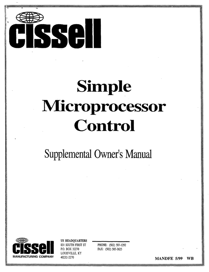
  9. Cissell DMP User manual

Cissell DMP User manual

Diagnostic
Microprocessor
Control
Supplemental Owners Manual
US HEADQUARTERS
831 SOUTH FIRST ST. PHONE: (502) 587-1292
P.O. BOX 32270 FAX: (502) 585-3625
LOUISVILLE, KY. 40232-2270
MANDMP (ECN5737) 1/00
Diagnostic Microprocessor Control (DMP)
The Cissell Diagnostic Microprocessor Control (DMP) is designed to manage the drying and cooling cycles
of the dryer. The controller is also programmed from the the factory with five different default programs as
described below. The operator has the flexibility to select the time for the drying and cool down cycles and
the drying temperature. The operator may also select either reversing or non-reversing basket action only if
the dryer is equipped for reversing. The operator may also re-program the default programs. See
paragragh 4.0.
1.0 General Operation
Dry Time
40 Minutes
30 Minutes
30 Minutes
25 Minutes
5 Minutes
Cool Time
5 Minutes
5 Minutes
5 Minutes
5 Minutes
2 Minutes
Temp. Set Point
185/195°F (85/91°C)
165°F (74°C)
150°F (66°C)
135°F (57°C)
150°F (66°C)
Reversing
No
Yes
No
Yes
No
Note: If an altered program is determined to be corrupted, the default program settings will be used.
Default Programs
Programs
1-TOWELS
2-SHEETS
3-MISC-1
4-MISC-2
5-EXTRA DRY
2.0 Features
1. Drying time: 0-60 minutes
2. Cooling time: 2-60 minutes
3. LED display of cycle time, set temperature, and actual temperature
4 Thermistor controlled temperature
5. Safety tumble cycle
6. Buzzer for end of cycle, audible alarm
7. Reversing/Non-reversing selection
8. Five user programmable programs
9. RPM display - (when equipped with rotational sensor only)
10. Monitors the sail switch operation
11. Monitors the lint door switch operation
12. Monitors the thermistor for operation
The minimum drying time is 0 minutes, and the minimum cooling time is 2 minutes. The maximum
drying or cooling time is 60 minutes. The drying temperature may be set from 100°F (38°C) to
185/195°F (85/91°C). The drying time, cooling time, or temperature may be modified during an
operating cycle.
If it is necessary to reset the drying and cooling times for the current cycle, press STOP once to
stop the dryer. Press STOP again to cancel the cycle.
If it is necessary to change programs during a current cycle, press STOP once to stop the dryer and
press STOP again to cancel the current cycle
DIAGNOSTIC MICROPROCESSOR CONTROL - FEATURES
Page 2
#1 Dryer Type: This DIP switch selects the type of dryer, i.e. OPL or Coin.
#2 Temperature Units: Selects °F or °C for the temperature display. Factory setting is for °F.
#3 Local/Remote Reversing: Preset at the factory; usually for local reversing. Remote reversing for
use with Cissell part # TU12874, Reversing Timer Board only.
#4 Sail Switch: Preset at the factory; usually set for the sail switch to be monitored.
#5 Lint Door Switch: Preset at the factory; usually set for the lint door switch to be monitored.
#6 Buzzer Timer: This DIP switch determines the length of time that the end of cycle buzzer will
remain on. OFF indicates that the buzzer will sound for 5 seconds when the drying cycle is
completed. ON indicates that the buzzer will sound continuously until the STOP button is
pressed, or the loading door is opened.
#7 Safety Tumble, Display Count, or Pay: If DIP Switch #1 is set for OPL, then DIP switch #7 in the
ON position enables the safety tumble. If DIP Switch #1 is set for Coin, then DIP switch #7 in the
ON position enables the display of the coin count. DIP switch #7 in theOFF position enables the
display of PAy, to indicate that coins are needed to run the dryer.
#8 Programming: This switch enables or disables the programming feature and should normally be in
the OFF position.
Diagnostic Microprocessor Control (DMP)
Switch #
1
2
3
4
5
6
7
8
Function
Dryer Type
Temperature Units
Local / Remote
Reversing
Sail Switch
Lint Door Switch
Buzzer Timer
Safety Tumble (OPL)
or Coin Count/Pay (Coin)
Programming
OPL
OFF
OFF
ON
OFF
OFF
ON
ON
OFF
Coin
ON (OPL=Off; Coin=On)
OFF (°F=Off; °C=On)
ON (Local=On; Remote=Off)
OFF (Enable=Off; Disable=On)
ON (5 Sec=Off; Continuous=On)
OFF
OFF (Disable=Off; Enable=On)
Dip Switch Functions Explained
3.0 DIP Switch Settings
The DMP has an 8-position DIP switch bank that is accessible from the back of the control board. By
switching these DIP switches, it is possible for the operator to customize the display and some of the
operating features of the dryer.
Page 3
OFF ON
OFF OFF
ON ON
ON OFF
#1 #7
SAFETY TUMBLE
NO SAFETY TUMBLE
COIN COUNT
PAY
DIPSWITCH
4.0 Programming
4.1 Set Dip Switch #8 to the ON position.
4.2 Select the desired program number to change. The LED should be flashing.
4.3 Select DRY TIME. Set the time with the UP/DOWN arrows.
4.4 Select COOL TIME. Set the time with the UP/DOWN arrows.
4.5 Select TEMPERATURE. Set the temperature with the UP/DOWN arrows.
4.6 Select reversing REV (illuminated) or non-reversing REV (not illuminated). To change basket direction and dwell
time, see section 6.0 Reversing Operation.
4.7 Press and hold the PROGRAM select button about 3 seconds until the LED stops flashing. The selected
program number is now programmed. If the PROGRAM button is pressed for less than 3 seconds, the controller
will cancel the program and display the next programs settings. If not programmed correctly, the display will
flash E2F for 4 seconds, and the default settings will be used. Follow steps 4.2 through 4.7 to re-program any
program number. When finished, set DIP Switch #8 to OFF. The programs are now stored.
4.8 During the program mode, if the UP/DOWN arrows, REV, or DISPLAY button is not pressed within 10
seconds the default program settings will be used.
5.0 Temporary Re-Programming of Current Programs (OPL only)
5.1 The Drying Time, Cooling Time, Temperature, and Reversing Mode of a program currently in use may be
modified simply by adjusting any or all of the program parameters for that program, as needed. Once a
modification has been made the current program LED will flash indicating that it has been modified.
5.2 Use the UP/DOWN arrows to adjust program time.
5.3 Use the Display Select button to choose between Drying Time, Cooling Time, and Temperature. Then use
the UP/DOWN arrows to adjust the times and temperature.
5.4 Toggle between reversing REV (illuminated) or non-reversing REV (not illuminated). * Only for dryers with the
reversing option.
5.5 To cancel this temporary programming mode push the STOP button once to stop the current cycle and once
more to cancel the modified program settings. The program will revert back to its original settings.
6.0 Reversing Operation
6.1 When the LOCAL reversing operation is selected, the reversing times are stored in the EEPROM which is
located on the controller board. If the values stored are determined to be invalid the clockwise and counter-
clockwise times will default to 60 seconds, and the dwell time will default to 4 seconds.
6.2 The reversing time program has the following sequence: (1) clockwise time, (2) dwell time, and (3) counter-
clockwise time.
6.3 To program new reversing times DIP switches #3 and #8 must be on.
6.4 Press and hold the reverse button (REV) for 3 seconds to display the clockwise time.
6.5 Use the UP/DOWN arrows to set the clockwise time within the range of 30-120 seconds.
6.6 Press REV to display the dwell time.
6.7 Use the UP/DOWN arrows to change the dwell time within the range of 3-10 seconds.
6.8 Press the REV button to display the counter-clockwise time.
6.9 Use the UP/DOWN arrows to change the counter-clockwise time within the range of 30-120 seconds.
6.10 Press the REV button to save these settings and leave DIP Switch #3 in the ON position and flip DIP Switch
#8 to the OFF position.
When the DMP controller is retrofitted to an existing dryer with the reversing feature, off board reversing will be
required and DIP Switch #3 on the DMP must be in the OFF position and the DMP must be connected to the
Reversing Timer Board, Cissell part # TU12874 for proper operation. The DMP settings for clockwise, dwell, and
counter-clockwise times are no longer valid when used with the Reversing Board. Instead these settings
are made on the Reversing Timer Board.
DIAGNOSTIC MICROPROCESSOR CONTROL - FEATURES
Page 4
9.0 Description of the OPL Control Panel (See illustration on page 7)
1. START. Starts or resumes the current program or cycle.
2. STOP. Temporarily halts the current cycle or cancels the current program.
3. REVERSING/NON-REVERSING (REV). Changes the selection between reversing and non-reversing dryer
action.
3.1 REVERSING LED. Illuminated when set for reversing.
4. UP/DOWN ARROWS. Increases or decreases the value in the display. In conjunction with the DISPLAY
button, these buttons are used to adjust the drying time, cooling time, temperature, clockwise time,
dwell time, counter-clockwise time, and minutes per coin (COIN only).
4.1 DISPLAY. Displays the drying time, cooling time, drying temperature, and diagnostic codes.
5. DISPLAY SELECT. Toggles the display between the drying time, cooling time, and temperature settings.
Pressing the DISPLAY button for 3 seconds allows the user to display the drying cycle temperature.
5.1 DRYING LED. Illuminated when in the drying cycle.
7.0 Rotation Sensor
The rotation sensor must read the key on the basket shaft. The sensor must be set approximately 1/4" from the key. Look
for the light on the sensor to come on as the key passes the sensor; this is a correctly operating sensor. If no light appears
either the sensor is out of range of the key or the sensor is bad. In addition, if the light stays on continuously then the sensor
is too close to the shaft or the sensor is bad.
8.0 Operational Check for the Board Diagnostics
8.1 dor indicates that the loading door is open.
8.2 ldr indicates that the lint door is open.
8.3 Cycle the dryer to check if the buzzer activates.
8.4 P-F indicates that the thermistor is short circuited or open circuited.
8.5 Hold the sail switch shut for a few seconds during start up -- Display reads FSS. To clear the display, release the sail
switch to normal operation, press STOP then press START.
8.6 Hold the sail switch open during operation for more than 3 seconds -- Display reads FSS. To clear the display,
release the sail switch to normal operation, press STOP then press START.
8.7 bbt indicates a broken belt condition or a faulty rotation sensor. * Only available on dryers with the rotation sensor.
8.8 Hold the START button to display the drum RPMs; the display will read r## where ## are the RPMs. * Only avail
able on dryers with the rotation sensor.
8.9 cln indicates that the lint door has not been opened within 10 hours of operation.
8.10 cln is displayed and the dryer will not start if the lint door has not been opened before 20 hours of
operation.
DIAGNOSTIC MICROPROCESSOR CONTROL - FEATURES
Page 5
7.1 Safety Tumble/Anti-Wrinkle
At the end of the cooldown cycle, the dryer will stop and display END. The DMP control will automatically
rotate the basket for 5 seconds every 2 minutes for a total of 20 minutes, until some function of the dryer is
activated/deactivated by the user.
5.2 COOLING LED. Illuminated when in the cooling cycle, or when the display is currently
showing the time for the cooling cycle.
5.3 TEMPERATURE LED. Illuminated when the display is showing the temperature setting.
6. PROGRAM SELECT. This button toggles through the five user programmable programs.
Holding this button will save a program, as indicated in section 4.7.
6.1 USER PROGRAM LEDS. Illumination shows which user program is currently being
displayed.
(Description of OPL Control Panel Continued)
DIAGNOSTIC MICROPROCESSOR CONTROL - FEATURES
Page 6
DIAGNOSTIC MICROPROCESSOR CONTROL - DETAILS OF
OPL CONTROL BOARD
Page 7
DIAGNOSTIC MICROPROCESSOR CONTROL - COIN FEATURES
10.0 Coin Keypad Interface
-START button to start or resume a cycle.
-TEMPERATURE button to select HIGH, MEDIUM, or LOW temperature.
-Two hidden buttons to increment or decrement the programmable time and temperature options.
11.0 Power-Up
Upon applying power to the dryer, the display will show PAy and the DRYING and COOLING LEDs
will be off until coins are deposited to increase the dryer run time. When time is displayed, the default
(LOW) temperature setting LED will be on until a different temperature setting is selected.
12.0 Power Failure
If a power loss occurs during operation, a cycle will not resume until the START button is pressed. To
cancel the remaining cycle, press the internal CLEAR button.
13.0 Coin Operation
The dryer run time is determined by the pre-programmed run time per coin and the number of coins
deposited into the dryer. The maximum time that can be accumulated and displayed is 99 minutes. The
drying time is the difference between the run time and the cooling time. The cooling time is pre-
programmed to be 2 to 5 minutes. The drying temperature can be selected from LOW, MEDIUM, or
HIGH temperature settings by pressing the TEMPERATURE button.
14.0 Coin Programming
14.1 The Coin board programming mode can only be entered when PAy is displayed. DIP switch #7 must
be in the off position.
14.2 Programming is enabled by setting DIP switch # 8 to the ON position.
14.3 The programming mode is entered by pressing and holding the CLEAR button for three seconds.
14.4 The programming follows the following parameter order:
1. Dryer run time per coin (DRYING), COOLING time, HIGH temperature setpoint,
MEDIUM temperature setpoint, LOW temperature setpoint.
2. An LED will be on to indicate which parameter is flashing on the display.
3. The hidden front panel increment and decrement keys are used to change the value.
4. The CLEAR button is used to recall the default value.
5. The START button is used to step to the next parameter.
6. After the last parameter, End will be flashing.
7. Press the START button one last time to store the settings and exit the program mode.
8. PAy will be displayed.
9. If it is determined that the data did not program correctly, the error message E2F will
flash for 4 seconds, and then the default coin parameters will be used.
14.5 The dryer run time per coin is programmable from 1 to 20 minutes with the default preset to 10 minutes.
14.6 The cooling run time is programmable from 2 to 5 minutes with the default preset to 2 minutes.
14.7 The three temperatures setpoints are programmable from 100°F (38°C) to 185/195°F (85/90°C) with
the following default settings: - HIGH equal to 185°F (85°C)
- MEDIUM equal to 150°F (66°C)
- LOW equal to 135°F (57°)
Page 8
DIAGNOSTIC MICROPROCESSOR CONTROL - COIN FEATURES
15.0 Stop
When in the Coin mode, the dryer will stop if the dryer door is opened while the dryer is running. If
the CLEAR button, located behind the board, is pressed, the dryer will stop, the dryer time is zeroed and
the display will show PAy.
16.0 Coin Count
16.1 The unit will count the number of coins deposited.
16.2 Setting DIP switch # 7 to the ON position will display the coin count since it was last reset.
16.3 To reset the count, press the CLEAR button and 00 will be displayed.
16.4 If the coin count is greater than 999, the display will flash 999.
16.5 Setting DIP switch # 7 to the OFF position will return the display to PAy.
17.0 Description of Coin Control Panel (See illustration on page 10)
1. START. Starts or resumes the current program or cycle.
2. HIDDEN KEYS. Used for programming in the coin mode - increases or decreases the
value in the display. In conjunction with the START button, these buttons are used to
adjust the drying time, cooling time, temperature, clockwise time, dwell time, counter-clockwise
time, and minutes per coin.
3. DISPLAY. Displays the drying time, cooling time, drying temperature, and diagnostics.
4. DRYING LED. Illuminated when in the drying cycle.
5. COOLING LED. Illuminated when in the cooling cycle, or when the display is
currently showing the time for the cooling cycle.
6. TEMPERATURE LED. Indicates temperature setting.
7. TEMPERATURE SELECT. This button toggles through the three temperature
selections.
8. INSTRUCTIONS. Instructions to start a drying cycle.
9. CLOCK SYMBOL. This symbol of a clock indicates that the time in the display is
counting down to zero.
Page 9
DIAGNOSTIC MICROPROCESSOR CONTROL
DETAILS OF COIN CONTROL BOARD
Page 10

This manual suits for next models

1

Other Cissell Controllers manuals

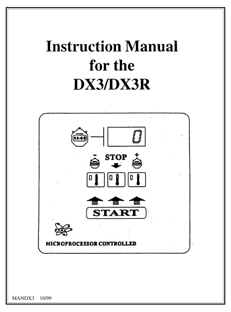
Cissell DX3 User manual

Cissell

Cissell DX3 User manual

Cissell SMPMANDFE User manual

Cissell

Cissell SMPMANDFE User manual

Cissell DX4 CONTROLLER User manual

Cissell

Cissell DX4 CONTROLLER User manual

Popular Controllers manuals by other brands

NovaStar VX400 user manual

NovaStar

NovaStar VX400 user manual

Digistar EZ3600 user manual

Digistar

Digistar EZ3600 user manual

USFilter STRANTROL SYSTEM 5 Installation & programming manual

USFilter

USFilter STRANTROL SYSTEM 5 Installation & programming manual

Sewhacnm SI 4400 instruction manual

Sewhacnm

Sewhacnm SI 4400 instruction manual

Aqua Medic Qube control Operation manual

Aqua Medic

Aqua Medic Qube control Operation manual

HARDKORR 10A SOLAR CHARGE CONTROLLER user manual

HARDKORR

HARDKORR 10A SOLAR CHARGE CONTROLLER user manual

IMG STAGE LINE DMX-510USB instruction manual

IMG STAGE LINE

IMG STAGE LINE DMX-510USB instruction manual

AL Tech ALTHC023 Installer Manual and Quick Guide

AL Tech

AL Tech ALTHC023 Installer Manual and Quick Guide

Alfalaval LKLA NC instruction manual

Alfalaval

Alfalaval LKLA NC instruction manual

Bluesky SB3000i Installation and operation

Bluesky

Bluesky SB3000i Installation and operation

Light Symphony iTimer Operating & installation guide

Light Symphony

Light Symphony iTimer Operating & installation guide

KEBCO COMBIVERT F6 Instructions for use

KEBCO

KEBCO COMBIVERT F6 Instructions for use

EP Solar EPHC10-EC series instruction manual

EP Solar

EP Solar EPHC10-EC series instruction manual

Zero88 Sirius 24 Installation and operation instructions

Zero88

Zero88 Sirius 24 Installation and operation instructions

FP-TECH Auto VH1 user manual

FP-TECH

FP-TECH Auto VH1 user manual

Smartswitch FC-006 installation manual

Smartswitch

Smartswitch FC-006 installation manual

New lift FST-2 manual

New lift

New lift FST-2 manual

EarthWise SOLiC 200 User instructions

EarthWise

EarthWise SOLiC 200 User instructions

manuals.online logo
manuals.online logoBrands
  • About & Mission
  • Contact us
  • Privacy Policy
  • Terms and Conditions

Copyright 2025 Manuals.Online. All Rights Reserved.