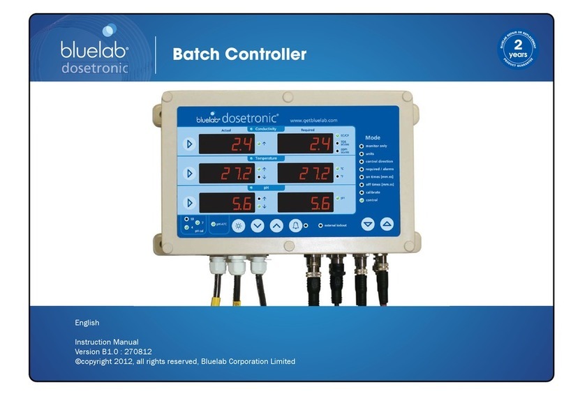
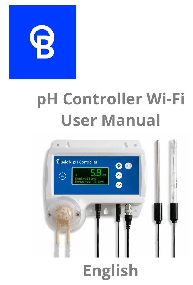
bluelab Pro Controller Wi-Fi User manual

Pro Controller Wi-Fi
User Manual
English

Contents
1.0 Introduction & Overview ................ 3
1.1 Features .......................................... 3
1.2 What’s in the box? .......................... 4
1.3 How it works ................................... 4
2.0 Setting up the Bluelab Pro
Controller ................................................ 7
2.1 Bluelab Pro Controller connection
panel ...................................................... 7
2.2 Connect the probes ....................... 7
2.3 Power up ......................................... 8
2.4 Bluelab Pro Controller control
panel ...................................................... 9
2.5 Bluelab Pro Controller modes .... 10
2.5.1 Monitoring only ............................... 10
2.5.2 Units ........................................... 11
2.5.3 Control direction ............................. 12
2.5.4 Required/alarms ............................. 13
2.5.5 On times ........................................... 15
2.5.6 Off times .......................................... 16
2.5.7 Calibrate ........................................... 17
2.5.8 Control ............................................. 18
2.6 Brightness control........................ 18
3.0 Installing the Bluelab Pro
Controller ..............................................19
3.1 Mounting the Bluelab Pro
Controller ............................................ 19
3.2 Placement of probes ................... 19
3.3 Manual override control ............. 20
3.4 Connecting dosers ....................... 20
3.5 Record your system set up ......... 22
4.0 Alarms & External Lockouts .........23
4.1 Connecting alarm & external
lockout cable ....................................... 23
4.2 Alarm & lockout cable functionality
.............................................................. 23
4.3 External lockout indicator ........... 25
5.0 Wi-Fi connection ............................ 26
5.1 Connect Pro Controller to Wi-Fi for
the first time ........................................ 26
5.2 Connect to a different Wi-Fi
Network ............................................... 27
5.3 Enable / Disable Wi-Fi and data .. 28
6.0 Probe Care & Maintenance .......... 29
6.1 Cleaning the pH probe ................. 29
6.2 pH Calibration ............................... 30
6.3 pH Probe care ............................... 32
6.4 pH Probe storage ......................... 33
6.5 Cleaning the Conductivity Probe 34
6.6 Conductivity Calibration .............. 36
7.0 Troubleshooting & Specifications 37
7.1 Troubleshooting guide ................. 37
7.2 Bluelab Pro Controller status
displays ................................................ 39
7.3 Firmware Update .......................... 40
7.4 Technical specifications ............... 41
8.0 Accessories and Parts ................... 43
8.1 Bluelab pH Probe replacement .. 43
8.2 Bluelab Probe Care Kits ............... 43
8.3 Bluelab pH Probe KCl Storage
Solution ................................................ 43
9.0 Warranty and Contact .................. 44
9.1 Bluelab limited warranty ............. 44

1.0 Introduction & Overview
1.1 Features
Built-in Wi-Fi (with option to disable)
Local and remote adjustment of control
settings via Edenic by Bluelab software
Data logging capability (via Edenic by Bluelab
software)
Monitor and automate
multi
-
part
nutrient and
pH dosing in reservoirs when paired with
Bluelab PeriPod dosers
Use Bluelab PowerPod to connect to other
mains operated dosers
Control of temperature requires use of
Bluelab PowerPod
Flashing high and low
alarms stop further
dosing
Dosing lockouts to protect from over
-
dosing
Auto resume dosing on restart after power
loss
Compressor protection on temperature
control
Simple push button pH calibration
Large, easy to read displays
Easy to navigate menu to
program and adjust
settings
‘P
lant safe
’
green LED
s
with adjustable
brightness
Replaceable double junction Bluelab pH Probe
Replaceable Bluelab Conductivity Probe
Separate stainless steel Bluelab Temperature
Probe Water resistant, wall mount design
What is Plant Safe?
Green lights are safe for continued growth during a plant’s fruiting stage when hours
of darkness are required.
What are Dosing Lockouts for?
They are a built-in safety feature that stops pH dosing if an error is detected in the
system (see FAQs for more detail).

1.2 What’s in the box?
1x Bluelab Pro Controller Wi-Fi
1x Getting started guide
1x Universal Power supply 24 VDC output
1x Conductivity Probe with 2 m (6') cable
1x pH Probe with 2 m (6') cable
1x Temperature probe with 2 m (6') cable
1x Alarm and external lockout cable
9x Calibration solution sachets
4x Mounting Screws
1.3 How it works
The Bluelab Pro Controller is designed to continually monitor and control the
conductivity, temperature and pH values of a solution.
It measures these using a separate probe for each parameter and using a connected
dosing system it can dose nutrient and pH correction solutions. The Bluelab Pro
Controller may also control a heating or cooling system via a connected Bluelab
PowerPod.
Actual readings / values
These are the current values measured by the conductivity, temperature, and pH probes.
Required readings / values
These are the target values or set points the Bluelab Pro Controller will maintain
within the reservoir for conductivity, temperature, and pH when in Control mode.
Dosing cycles
Automated control of conductivity, pH and temperature is achieved by dosing. The
Bluelab Pro Controller does this with a dosing cycle method that consists of an on
time and an off time.
OnTime
The time that the pump runs for in each dosing cycle. Or in the case of temperature,
how long the heater or cooler is turned on for. As a guide, three dosing cycles should
change the reservoir by 0.1 pH points.
OffTime
The delay time between each dose (or OnTime). This gives the system time to mix the
stock solution into the reservoir thoroughly, so the Bluelab Pro Controller measures
the solution accurately. Start with a longer OffTime and reduce it over time.

IMPORTANT
If the on time is too short, it is possible that the Bluelab Pro Controller won’t be
able to dose enough to keep up with the changing nutrient/pH levels, even if it
doses every dosing cycle.
If the on time is too long, the value is likely to overshoot; i.e. a single dose
changes the value so much it goes over the desired value.
Hint: The mixing time of the reservoir can be estimated by manually adding
sufficient nutrient to significantly shift the conductivity value, while timing how
long it takes from adding the nutrient, to when the conductivity value becomes
stable.
Dosing lockouts
Some conditions will cause the Bluelab Pro Controller to stop controlling. These are
called dosing lockouts. This is how the five types of dosing lockouts work:
Measurement range limits
Each of the measurement types (conductivity, temperature and pH) have a
measurement range within which they can measure. Conductivity, for example, can be
measured between 0.0 EC and 5.0 EC; temperature between 0°C and 50°C; pH
between 0.0pH and 14.0pH.
If values outside these limits are sensed, the Bluelab Pro Controller will indicate that it
is under or over range by flashing the display and displaying “ur” or “or” in the affected
measurement type. Dosing will immediately stop in that measurement type. pH or EC
“ur/or” will also stop EC or pH dosing.
Alarms
When alarms are turned on, and the Bluelab Pro Controller senses that either EC or pH is
beyond the set high or low alarm values, all nutrient dosing will stop (both EC and pH).
IMPORTANT
Alarms are not just warnings that values have shifted away from the required
value - they stop dosing. Be careful not to set alarm values which are too close to
the required values, as they may result in the Bluelab Pro Controller going into
alarm because of small variations in measured values.
When the values return to within the limits of the set alarms, the alarm state ceases,
and after a 60 second countdown, the Bluelab Pro Controller begins controlling again,
dosing as required. The alarm state can also be cancelled by switching alarms off
(pressing the alarm button or switching alarms off via Edenic). After a 60 second
countdown the Bluelab Pro Controller will begin controlling again.
Ineffective Control Lockout
The Bluelab Pro Controller continually checks to ensure that dosing is having an effect.
It will go into lockout if 15 dosing cycles of any of the three measurement types
(conductivity, temperature, or pH) do not move the measured value by at least 0.1 EC,

1°C, or 0.1 pH in the desired direction. This is called the ineffective control lockout, and is
enabled by default, but can be disabled via Edenic.
The Bluelab Pro Controller will indicate it is in ineffective control lockout by flashing the
display and displaying a code in the affected measurement type - for example “PH IC” to
indicate that pH is in ineffective control.
IMPORTANT
The ineffective control lockout is useful to stop dosing pump operation if stock
solution tanks have emptied, or a hose has fallen out of a reservoir, for example.
However for a batch dosing system where fresh water is being added to the
reservoir at the same time as dosing is occurring, it may be better to disable this
feature.
Low EC Lockout
The Bluelab Pro Controller will stop dosing nutrient solution if the measured conductivity
drops below 0.2EC (2CF, 100TDS, 140ppm). This is called the Low EC Lockout, and is
enabled by default, but can be disabled via Edenic.
The Bluelab Pro Controller will indicate it is in low EC lockout by flashing the conductivity
display, and displaying “EC 0.2LO.” As soon as the measured conductivity rises above 0.2,
the Pro Controller will resume dosing again after a 60 second countdown.
IMPORTANT
The Low EC Lockout is useful to stop dosing if the conductivity probe is taken out
of the reservoir, or if the solution level falls below the probe level.
However, when dosing into fresh, RO or deionised water is required this
lockout may need to be disabled.
External Lockout
Dosing can be stopped by external flow switches, float switches, or other sensors
connected to the Bluelab Pro Controller via the Alarm and External Lockout cable. This
is called an external lockout.
When the Pro Controller is in external lockout, the external lockout LED will light, and the
displays will flash “EL” and either “nc” or “no” or “ncno” depending on which switch has
been activated.
As soon as the switch position returns to normal, the Bluelab Pro Controller will resume
controlling after a 60 second countdown.
IMPORTANT
The External Lockout feature can be used to stop dosing when a tank level gets too
low, a pump stops, or solution feeding out is taking place.

2.0 Setting up the Bluelab Pro Controller
2.1 Bluelab Pro Controller connection panel
2.2 Connect the probes
It is recommended to test the Bluelab Pro Controller prior to mounting. Attach all three
probes to the controller, plug in the power adaptor, place probes into solution and wait
a few minutes for the readings to stabilise.
pH Probe
Line up the lugs of the BNC probe connector with
the receptacle on the Bluelab Pro Controller
labelled ‘pH’.
Fasten securely by pushing the pH probe
connector on and twisting one quarter turn.
Conductivity Probe
Line up the four-pin connector on the conductivity
probe with the receptacle on the Bluelab Pro
Controller labelled ‘COND’. Push and screw the
collar fully into the receptacle.
Temperature Probe
Fully insert the temperature probe connector into
the Bluelab Pro Controller receptacle marked
‘TEMP/ATC’.
Push connector
Twist & attach
Line up four pins
Push & twist
Temp/ATC
connector
Twist & attach
Alarm connector
Main power
connector
Doser connector
Temperature
probe connector
pH probe
connector
Conductivity
probe connector

2.3 Power up
Select and connect the appropriate mains plug
adaptor for your country to the power supply unit.
Connect the power adaptor into the Bluelab Pro
Controller receptacle marked ‘PWR’.
Plug the power adaptor into a mains outlet and
switch it on.
The default setting, when the unit is first powered up,
is ‘monitor only’ mode.
Note: pH calibration should be completed before first use to ensure pH readings
are accurate.
Connect
power
adaptor

2.4 Bluelab Pro Controller control panel
We recommend familiarising yourself with the different settings
before installing/mounting the controller.
Mode selection
buttons
Units
External lockout
indicator
Mode menu
Power supply connector
Doser connector
Alarm & external lockout
connector
Value increase/decrease buttons
pH probe connector
Temperature probe connector
Conductivity probe connector
Alarm button & indicator
Settings button
pH ATC indicator
pH calibration
indicators
pH
Temperature
Conductivity
Measurement
selection buttons
Actual readings
Control direction indicators
Required readings

2.5 Bluelab Pro Controller modes
The Bluelab Pro Controller has two modes of operation (monitor and control) and six
set-up modes.
Use the Mode Selection buttons (‘’ and ‘’) to change modes. Once in the required
mode, select the measurement to adjust with the Selection buttons (‘’) and adjust the
value up and down with the Value Increase/Decrease buttons (‘∧’ and ‘∨’).
The Mode is selected using the Mode Selection buttons below
the Mode menu.
2.5.1 Monitoring only
Monitor only mode shows only the actual values/readings. No control action occurs.
23
6.3
2..7
2.7
23
6.3

2.5.2 Units
Units
mode
allows
the
units of
measurement
to
be changed
for
conductivity
and
temperature.
1.
Select ‘Units’ mode.
2. Select measurement to adjust (‘’).
3. Press the value increase/decrease buttons to select the desired unit of
measurement.
Note: To change between EC and CF, press the measurement button twice when
this indicator is lit. CF is 10x EC e.g. 2.8EC = 28CF. pH has no selectable units.
23
2..7
Units
Units mode
selected

2.5.3 Control direction
Control Direction mode
allows the dosing direction to be set for the measurement
value.
1.
Select ‘Control Direction’ mode.
2. Select measurement to adjust (‘’).
3. Press the value increase/decrease buttons to change the control direction.
IMPORTANT:
The control direction for each measurement value must be selected
based on the requirements of the system, and the correct stock solutions, pH
adjusters and temperature device must be used.
Control direction options:
Raise ↑ or lower ↓ or OFF
Note: OFF means that control
of this measurement is turned
off. This allows some
measurements to be controlled
while others are just
monitored.
23
2..7
Units
Control
direction
mode
selected

2.5.4 Required/alarms
This mode is used to set the ‘required’ or ‘target’ levels for conductivity, temperature
and pH in your system. It is also used to set alarm levels.
‘Required’ is the value you need the Bluelab Pro Controller to maintain through
dosing.
High and low alarm levels can be set. Alarms can be turned on or off in any mode
with the Alarm button. The LED indicator next to the Alarm button indicates whether
alarms are switched on.
Setting conductivity, temperature and pH required and alarm levels.
1. Select ‘Required/alarms’ mode.
2. Select the measurement to adjust ( ‘’ )
3. Press the same measurement selection button to toggle between the following
values; required level (rd) for conductivity and pH, on and off values for
temperature, high alarm value (AL.HI), and low alarm value (AL.LO) for that
measurement.
The value selected to edit will be displayed brightest.
4. Adjust values using the value increase/decrease buttons.
(Note: If the value you are changing reaches another alarm high, alarm low or required
value, it will be automatically pushed so they do not overlap.
rd
Al.h
1
Units
Required / alarms
mode selected
Required value
Al.l0
2..0
1.8
1.1
Alarm high value
Alarm low value

Temperature required / alarms
Temperature is difficult to maintain at a
constant level using on and off times, so the
Bluelab Pro Controller manages it differently to
conductivity and pH.
It is normal practice to set the temperature on
time to ‘continuous’, which allows the
heater/cooler to operate until the ‘temperature
off’ value is reached.
For example, if you are heating a tank or
reservoir, when the “temperature on” value is
reached, heating will be turned on. When the
“temperature off” value is reached, it will be
turned off.
Alarm
and Required
‘Quick
-
set’
Use the Quick-set features to quickly set the “required”, “alarm high” and “alarm low”
values for all three measurements. The alarm values are taken from the actual
readings, so ensure your system is stable before using the Quick-set function.
1.
In ‘Required / Alarms’ mode
select the measurement you
want to ‘quick-set’.
2. Press the alarm button.
3. Quick-set only sets the required
and alarm vales for the selected
measurement, so repeat steps 1
& 2 for the other measurements
required.
This table shows the values that are
applied when ‘quick-set’ is used.
‘Quick-set’ Alarm Values
Alarm Low Required Alarm High
Conductivity
Actual value –
0.2 EC / 2 CF
100 TDS
140 ppm
Actual
value
Actual value +
0.2 EC / 2 CF
100 TDS
140 ppm
Temperature
Actual value –
3°C / 5 °F
Actual
value
Actual value +
3°C / 5 °F
pH Actual value –
0.5pH
Actual
value
Actual value +
0.5pH
24
Al.h
1
Temperature off
value
Temperature on
value
Al.l0
30
26
22
Alarm high value
Alarm low value
Temperature Control Off
Temperature Control O
n
Temperature Control Off
26°C
24°C
16°C
If using a Temperature
Lower/Cooling Device
If using a Temperature
Raise/Heating Device

2.5.5 On times
The
o
n
t
ime can be set from one second to ten minutes in one second intervals.
During dosing on time, the dose direction indicators next to the Actual values will
flash.
For information on calculating on times for multi part nutrients see Bluelab PeriPod
manual.
Setting ‘
o
n
t
imes’
1. Select ‘on times’
mode.
2. Select measurement
to adjust ( ‘’ ).
3. Press (or hold down)
the ‘Value Increase /
Decrease’ buttons to
change the on time
value.
Programmable from 0-10
mintues in one second
increments.
Note:
0 seconds = continuous
(cont),
which
means
the
Bluelab
®
Pro Controller will
dose until the required value is reached WITHOUT stopping to allow the tank to mix.
This should be used under special circumstances, as unless closely monitored,
overshooting is likely.
The ideal on time is the time that the doser has to dose for (pumps actually
running), in order to shift the EC by just less than 0.1 EC. Any more than 0.1EC,
and the EC can overshoot, as one dose may take it over the required value. Any less
will increase the time the system needs to dose up to the required levels. If time to
reach the required EC level is not very important (recirculating systems change
slowly, and can be corrected slowly) a shorter on time (maybe 2 or three doses to
lift the EC by 0.1) is fine.
The on time for pH will be quite different to EC, so will need to be found in the same
way, but shifting 0.1 pH instead.
Slowly add equal parts of the nutrient that will be used in small
quantities and wait for it to mix. Keep adding small quantities like this,
waiting for it to mix each time, until the EC reading just increases to the
next 0.1 step.
Now, measuring exactly how much you are adding, add small equal
quantities of nutrient, again waiting for it to mix after each addition, until
the EC reading just reaches the next 0.1 step.
The amount of nutrient added to reach the second step from the first is
the amount needed to shift the EC by 0.1.
On times
mode
selected
0.53

Work out how long the doser has to run to deliver that quantity. For
example, 140 mls of each nutrient was required to produce this shift. For
an M3 PeriPod (120mls per minute per pump = 2 mls per second), then 70
seconds is required. 60 seconds (which is slightly less) would be a good
on time.
2.5.6 Off times
The 'off time' is the delay time between each dose which allows the tank to
thoroughly mix, and for EC & pH readings to stabilise. The 'off time' can be set from
1 to 60 minutes.
Start with a long ‘Off Time’ and reduce gradually, ensuring the system is not
overshooting. The more thorough the mixing in the tank, the shorter the ‘Off Time’
can be.
Setting ‘
o
ff
t
imes’
1. Select ‘off times’
mode.
2. Select
measurement to
adjust (‘’).
3. Press (or hold
down) the Value
Increase/Decreas
e buttons to
change the off
time.
Programmable from 0-59
minutes and 50 seconds
in ten second increments.
Off times
mode
selected
59.50

2.5.7 Calibrate
Calibrate mode allows calibration of the Bluelab Pro Controller to conductivity and pH
probes.
1.
Select ‘calibrate’ mode.
2. Select measurement to
calibrate (‘’). Either
Conductivity or pH.
3. Follow the directions in
section 6 of this manual.
Please always clean before calibration. Refer to section 6 for
cleaning and calibration instructions.
pH
p
robe
Calibration is important before
first
use, and is then required regularly to
ensure pH measurements and dosing are accurate. Bluelab recommend that you
calibrate pH every 30-days. To help remind you the Pro Controller has a built in 30
calibration timer.
Conductivity probe is factory calibrated. It is unlikely that you will need to calibrate it,
but it can be calibrated if required. Often cleaning the probe is all that is required.
Please always clean before calibration. Refer to section 6 for cleaning and calibration
instructions.
Calibrate
mode
selected
2.9
7.0

2.5.8 Control
When in control mode, the Bluelab Pro Controller monitors the actual readings
from the probes and triggers dosing cycles to reach and maintain the measurement
values set in the ‘Required/ Alarms’ mode.
For dosing to occur a separate doser (not included) must be connected to the
Bluelab Pro Controller with the dosing cable provided.
1.
Select ‘Control’ mode.
2. The Bluelab Pro
Controller triggers
dosing in order to reach
and maintain the
nutrient, pH and
temperature values set
in the required/alarms
mode.
When the system is
dosing the control
direction indicator LEDs
will flash.
2.6 Brightness control
1.
Press
the
‘
Settings
’
button.
2. Press the br selection button.
3. Adjust the brightness by using the
increase/ decrease buttons.
4. Press the ‘Settings’ button to save
brightness level.
18
1.1
Control
mode
selected
5.8
0.9
16
5.9
Required
Actual
data
prou
br

3.0 Installing the Bluelab Pro Controller
3.1 Mounting the Bluelab Pro Controller
Se
lect a suitable location for the Pro
Controller:
So, the probes can comfortably
reach the tank/reservoir or sample
pot and be always immersed in
solution.
Near an electrical mains outlet.
Within Wi-Fi range.
At a suitable height to see the
display and for easy operation.
Position the Pro Controller away
from direct sunlight and risk of
water, nutrient or pH adjuster
damage.
Fix the fasteners through the desired
mounting holes in the top and bottom
of the case.
3.2 Placement of probes
All probes must be
submerged in the solution for measurement.
The Bluelab conductivity probe measures solution temperature and provides
automatic temperature compensation for the pH measurement. The temperature
displayed on and controlled by the Pro Controller is the temperature measured by
the Bluelab Temperature probe.
Do not pour concentrated nutrient solution or pH adjuster directly onto probes
when in the reservoir, as very strong acid may damage the probes or trigger
alarms.
For accuracy, ensure the conductivity and pH probes are in an area where the
reservoir/tank solution is well mixed or in a sample pot.
If the Pro Controller is used to control solution temperature, the temperature
probe should also be placed in the reservoir or sample pot. If used to control air
temperature, it should be placed in an appropriate position outside the reservoir.
1.
Remove the storage cap from the pH probe by
gripping the top of the cap and gently twisting
the base one rotation to loosen. Slide the
storage cap off the pH probe.
Mounting holes at top
Mounting holes at bottom

2.
Fit the (optional) pH probe holder to the stem of
the pH probe using a gentle twisting motion. Be
careful not to bend or flex the probe stem.
3.
Place the pH probe into the
tank/reservoir and
push the suction cup onto the side of the
tank/reservoir so the pH probe tip will stay
submerged in the solution and will not get
damaged. The pH probe can be fully
submerged.
4.
Place the conductivity probe (and the
temperature probe, if used for solution
temperature) into the tank/reservoir alongside
the pH probe
3.3 Manual override control
Manual override lets you manually dose conductivity, temperature or pH. This can
be used to prime dosers or to manually bring a system to required levels quickly.
1.
Select ‘monitor’
mode
2. Press and hold the
measurement
button of the
measurement you
want to dose.
3. Press both mode
buttons together.
4. Continue to hold
the measurement
button while
dosing and release
it to stop.
3.4 Connecting dosers
The Bluelab Pro Controller must be connected to a Bluelab doser (not included) via
the dosing cable for dosing to occur. Up to three M3, M4 or L3 PeriPods can be
connected (daisy-chained) when dosing multi-part nutrients. Other mains-powered
dosers and temperature control systems can be connected via the Bluelab
PowerPod (not included).
18
1.2
Monitor
mode
selected
6.5
1.3
16
6.8
Table of contents
Other bluelab Controllers manuals
Popular Controllers manuals by other brands
Emerson
Emerson RTS FQ operating manual
CALECTRO
CALECTRO CALAIR-PR-230V Installation instruction
HP
HP P420 specification
Neptune Systems
Neptune Systems AquaController Apex Setup guide
elsner elektronik
elsner elektronik KNX S2 Technical specifications and installation instructions

SmartieParts
SmartieParts 9x installation instructions
