BlueNova HC User manual

User Manual
HC (High Current)
Product Range
Document Revision No.
Ver. 1.0.1
Revision Date
2021-01-22
Approved by
J.P. Verster

User Manual
High Current Product Range
2 Erica Way Office: +27 21 205 2000
Somerset West Business Park Technical Support: support@bluenova.co.za
Somerset West, 7130 Website: www.bluenova.co.za
.A. DOCUMENT SCOPE
Congratulations on purchasing a high quality BlueNova® product.
This document covers structural information, assembly & installation instructions, troubleshooting, safety &
maintenance instructions, storage guidelines as well as emergency / first aid procedures specific to the
BlueNova® High Current (HC) product range.
If you are unsure whether this document is applicable to your battery, or if you have any questions or comments,
kindly contact BlueNova® Technical Support:
Office: +27 21 205 2000 E-mail: support@bluenova.co.za
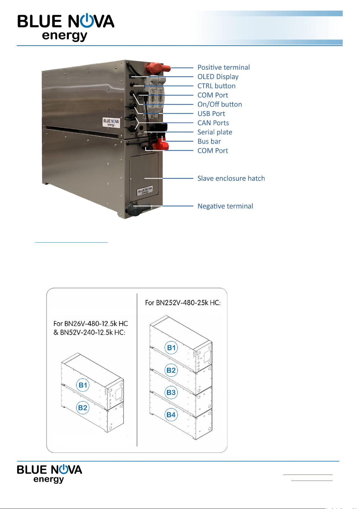
B. STRUCTURAL OVERVIEW
The BlueNova® HC range consists of single- and multi-enclosure batteries. The number of enclosures per battery
as well as the weight & dimensions of each enclosure are listed below:
#
Product Name
Enclosures per battery
Qty
Dimensions L x W x H
Weight (total)
1
BN13V-240-3.2k HC
1
51 x 21 x 31cm
38kg
2
BN13V-480-6.3k HC
1
80 x 21 x 31cm
75kg
3
BN26V-125-3.3k HC
1
51 x 21 x 31cm
38kg
4
BN26V-240-6.3k HC
1
80 x 21 x 31cm
75kg
5
BN26V-480-12.5k HC
2
2 x (80 x 21 x 31cm)
160kg
6
BN52V-125-6.5k HC
1
80 x 21 x 31cm
75kg
7
BN52V-240-12.5k HC
2
2 x (80 x 21 x 31cm)
160kg
8
BN52V-480-25k HC
4
4 x (80 x 21 x 31cm)
320kg
The following components should be included in the packaging of each battery:
Product (V-Ah-kWh)
Bolt set*
Bus bar**
Terminal
sleeves
Fuse(s)
1
BN13V-240-3.2k HC
2
–
1 POS / 1 NEG
1 x 125A
2
BN13V-480-6.3k HC
2
–
1 POS / 1 NEG
2 x 160A
3
BN26V-125-3.3k HC
2
–
1 POS / 1 NEG
1 x 125A
4
BN26V-240-6.3k HC
2
–
1 POS / 1 NEG
2 x 125A
5
BN26V-480-12.5k HC
4
1
1 POS / 1 NEG
2 x 160A
6
BN52V-125-6.5k HC
2
–
1 POS / 1 NEG
1 x 125A
7
BN52V-240-12.5k HC
4
1
1 POS / 1 NEG
2 x 125A
8
BN52V-480-25k HC
8
3
1 POS / 1 NEG
2 x 160A
* One bolt set consists of 1 x bolt, 1 x washer & 1 x spring washer.
** Bus bars include positive (red) and negative (black) insulation sleeves.
User Manual
High Current Product Range
2 Erica Way Office: +27 21 205 2000
Somerset West Business Park Technical Support: support@bluenova.co.za
Somerset West, 7130 Website: www.bluenova.co.za
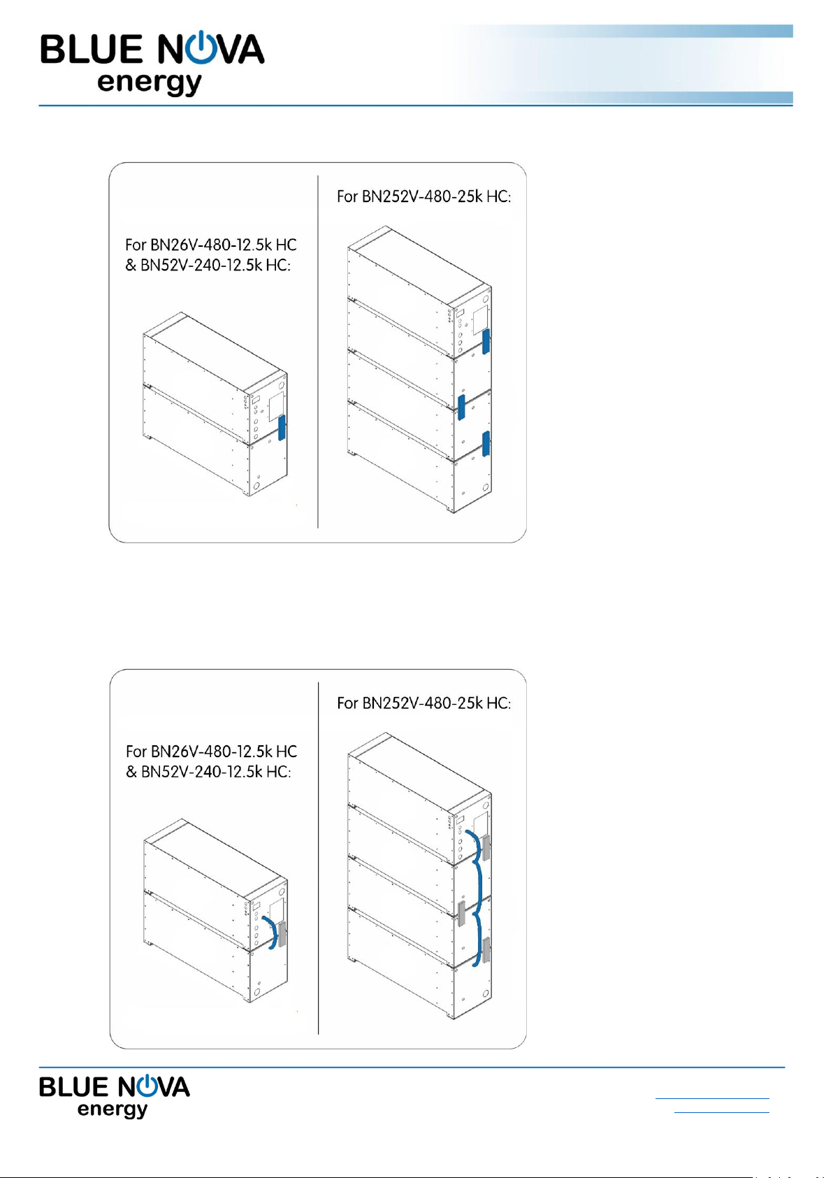
C. ASSEMBLY INSTRUCTIONS
Note: Single enclosure batteries require no assembly & are not included below.
STEP 1 : Stack enclosures
User Manual
High Current Product Range
2 Erica Way Office: +27 21 205 2000
Somerset West Business Park Technical Support: support@bluenova.co.za
Somerset West, 7130 Website: www.bluenova.co.za
STEP 2 : Connect enclosures with bus bars
Connect the enclosures in serie: B1(-) to B2(+) ; B2(-) to B3(+) ; B3(-) to B4(+) etc. as illustrated.
STEP 3 : Interconnect BMS
User Manual
High Current Product Range
2 Erica Way Office: +27 21 205 2000
Somerset West Business Park Technical Support: support@bluenova.co.za
Somerset West, 7130 Website: www.bluenova.co.za
D. INSTALLATION
1. VOLTAGE-BASED INSTALLATION
If the battery is not connected to hardware that is serial communication compatible, the following values
highlighted in blue must be set on the inverter/charger for 13V HC batteries:
Parameter
Cell V
Value
Comment
V high set
3.51 V
14.1 V
Typical bulk/absorption charge setpoint.
V float
3.47 V
13.9 V
Charger must reconnect when this voltage is reached.
V reconnect
3.20 V
12.8 V
Mains or generator must reconnect to charge batteries.
V low set
3.06 V
12.3 V
Inverter must switch off the load.
If the battery is not connected to hardware that is serial communication compatible, the following values
highlighted in blue must be set on the inverter/charger for 26V HC batteries:
Parameter
Cell V
Value
Comment
V high set
3.51 V
28.1 V
Typical bulk/absorption charge setpoint.
V float
3.47 V
27.8 V
Charger must reconnect when this voltage is reached.
V reconnect
3.20 V
25.6 V
Mains or generator must reconnect to charge batteries.
V low set
3.06 V
24.5 V
Inverter must switch off the load.
If the battery is not connected to hardware that is serial communication compatible, the following values
highlighted in blue must be set on the inverter/charger for 52V HC batteries:
Parameter
Cell V
Value
Comment
V high set
3.51 V
56.2 V
Typical bulk/absorption charge setpoint.
V float
3.47 V
55.5 V
Charger must reconnect when this voltage is reached.
V reconnect
3.20 V
51.2 V
Mains or generator must reconnect to charge batteries.
V low set
3.06 V
49.0 V
Inverter must switch off the load.
IMPORTANT: Inverter/charger voltage calibration
Some inverters/chargers have been known to return inaccurate results when measuring voltage.
In such cases, the inverter/charger should be calibrated as follows:
Compare the voltage values displayed by the inverter/charger with that of a calibrated voltmeter.
If the actual voltage differs by more than 100mV from that measured by the inverter/charger, apply this
difference to the highlighted values above (i.e. if actual voltage = 56V while inverter voltage = 56.5V,
the voltage difference = 0.5V should be subtracted from each of the set values above).
Note: Some inverters/chargers have pre-programmed lead-acid related algorithms & functionalities such as auto-
desulfation and equalisation. These functionalities should be disabled, where possible.

User Manual
High Current Product Range
2 Erica Way Office: +27 21 205 2000
Somerset West Business Park Technical Support: support@bluenova.co.za
Somerset West, 7130 Website: www.bluenova.co.za
2. SERIAL COMMUNICATION
BlueNova® HC batteries include serial communication functionality via CAN protocol. Connecting a BlueNova®
HC battery to a compatible inverter, charger or other third-party hardware device normally negates the necessity
of manual voltage-based installation procedures, as described in the section above.
The installation procedure for serial integration varies and is determined by the serial-compatible peripheral
hardware that is being integrated with.
3. PARALLEL CONNECTION
BlueNova batteries with 123Smart firmware version 5.4 & higher as well as BMMC firmware version 2.5 & higher
include MultiCap™ technology. Batteries with MultiCap™ can be connected in parallel to each other to increase
overall capacity, regardless of the age difference and/or rated capacity difference between any two of the
batteries in the parallel configuration ONLY IF ALL of the requirements below are met:
a. The nominal voltage of all parallel-connected batteries is the same (i.e. 52V), and
b. The installed capacity @C10 of the largest battery in the parallel configuration is no larger than 4 x the
installed capacity @C10 of the smallest battery in the same configuration, and
c. The correct firmware versions are installed on all batteries in the configuration & updated accordingly, and
d. Each battery is operating within its warranty period.
Parallel-connected battery configurations should always be connected to the inverter/charger from both ends of
the configuration, as illustrated in either of the 2 x examples below:

User Manual
High Current Product Range
2 Erica Way Office: +27 21 205 2000
Somerset West Business Park Technical Support: support@bluenova.co.za
Somerset West, 7130 Website: www.bluenova.co.za
4. MONITORING
4.1 On-Board Monitoring
Immediately after switching the battery on, the following splash screens will be displayed:
Splash
screen 1:
The BlueNova® logo is displayed, as well as the currently installed
BMS firmware version.
Splash
screen 2:
52V_4k_HC
52V_125_6.5
VICTRON 250
Line 1 & 2 : Abbreviated product/model information.
Line 3: Inverter firmware details. Note: Victron 250 is used for
batteries installed without serial integration.
Splash
screen 3:
Parallel
Batteries
N = 1
Displays the currently set parallel configuration. For single batteries
not connected in parallel, N should be 1.
After the above splash screens have been displayed for a few seconds each, the display will settle on page 1
below. Press the CTRL button to scroll to the next page in sequence:
Page 1:
Vbat:53.14V
Ibat:0.000A
SOC :99.99%
>> Battery voltage (actual)
>> Current (positive value = charge ; negative value = discharge)
>> State-of-charge
Page 2:
Energy out:
0.446kWh
SOH:99.99%
>> Total energy discharged from the battery since production.
>> State-of-health
Page 3:
Vch: 3.325V
Vcl: 3.320V
VC info ->
>> The highest cell voltage measured over any single cell.
>> The lowest cell voltage measured over any single cell.
>> Cell voltage submenu. See next table below.
Page 4:
Tmax:20.00C
MCU ID:321f
>> The average ambient temperature inside the enclosure(s).
>> Unique micro-controller unit identification number.
Page 5:
State
OK
The current state of the battery is displayed here.
If State = Err please see F. TROUBLESHOOTING below.
Page 6:
FW:BMMC 2.4
G#:8eb7c95e
PO:N=1 I=1
<< Battery Management & Monitoring Controller firmware ver.
<< Unique number used for debugging during production.
<< Currently set parallel configuration. See D. INSTALLATION
Page 7:
OVERRIDE?
PRESS+HOLD
Override procedure prompt for recovery from over-discharge.
See F. TROUBLESHOOTING > 2. Recovery from over-discharge
User Manual
High Current Product Range
2 Erica Way Office: +27 21 205 2000
Somerset West Business Park Technical Support: support@bluenova.co.za
Somerset West, 7130 Website: www.bluenova.co.za
Individual cell voltages can be viewed by accessing the cell voltage submenu from page 3:
Page 3:
Vch: 3.325V
Vcl: 3.320V
VC info ->
Scroll to page 3 illustrated on left. The arrow in the last line
VC info -> indicates a submenu. Press & hold the CTRL button for
about 2 seconds to access this submenu.
Page 3.1:
Vc1: 3.320V
Vc2: 3.320V
Vc3: 3.321V
<< Cell 1 voltage (actual)
<< Cell 2 voltage (actual)
<< Cell 3 voltage (actual)
Page 3.2:
Vc4: 3.321V
Vc5: 3.321V
Vc6: 3.321V
<< Cell 4 voltage (actual)
<< Cell 5 voltage (actual)
<< Cell 6 voltage (actual)
Page 3.3:
Vc7: 3.321V
Vc8: 3.321V
Vc9: 3.321V
<< Cell 7 voltage (actual)
<< Cell 8 voltage (actual)
<< Cell 9 voltage (actual)
Page 3.4:
Vc10:3.321V
Vc11:3.321V
Vc12:3.321V
<< Cell 10 voltage (actual)
<< Cell 11 voltage (actual)
<< Cell 12 voltage (actual)
Page 3.5:
Vc13:3.322V
Vc14:3.322V
Vc15:3.322V
<< Cell 13 voltage (actual)
<< Cell 14 voltage (actual)
<< Cell 15 voltage (actual)
Page 3.6:
Vc16:3.322V
<< Cell 16 voltage (actual)
Press the CTRL button again to jump back to page 3.1 above. Press & hold the CTRL button for 2 seconds to exit
submenu & return to one of the main pages.
Once configured, you should be able to remotely monitor your battery via the BlueNova Remote Monitor service
by navigating to http://brm.bluenova.co.za from remote internet-connected locations.
5. UPDATING FIRMWARE
You can update your battery’s firmware locally (from a USB-connected laptop) or remotely (from a compatible
internet-connected third-party device, such as a desktop PC, laptop or smartphone).
For firmware update procedures, kindly contact BlueNova Technical Support.

User Manual
High Current Product Range
2 Erica Way Office: +27 21 205 2000
Somerset West Business Park Technical Support: support@bluenova.co.za
Somerset West, 7130 Website: www.bluenova.co.za
E. MAINTENANCE
1. General Guidelines
a. Do not short circuit the battery terminals.
b. Do not use the battery without a BlueNova® approved integrated BMS solution.
c. Do not disassemble, pierce, cut or in any way physically alter any part of the battery.
d. Do not burn, incinerate or otherwise subject the battery to extreme heat.
2. Storage Instructions
a. Ensure that the battery is switched off when stored.
b. Disconnect the communication cable.
c. Always store batteries in a cool and well-ventilated area –ideally 25°C ± 3°C.
d. Store away from moisture and heat.
e. Do not store batteries upside down for overly long periods.
f. Check the open circuit voltage of stored batteries at least once per month. Recharge batteries sufficiently and
frequently enough to prevent the open circuit voltage falling below 40V.
g. Ensure that the stored battery’s state of charge is always above 50%. 100% SOC is optimal.
F. TROUBLESHOOTING
All BlueNova® products contain integrated circuitry as a safety measure against possible damage from electrical
malfunction. Under such conditions, one of the following errors will be displayed on the integrated OLED display.
Please follow the procedure described in each case:
1. List of error messages
Error no.
Displayed:
Procedure:
Error 1:
State
Err
BmsCRCfail
Please contact BlueNova Technical Support.
This error is used during production for debugging & should not be
encountered in the field.
Error 2:
State
Err
BmsCelComs
Please contact BlueNova Technical Support.
This error is used during production for debugging & should not be
encountered in the field.
Error 3:
State
Err
BmsCommsTO
Please contact BlueNova Technical Support.
This error is used during production for debugging & should not be
encountered in the field.
Error 4:
State
Err
BmsBadData
Please contact BlueNova Technical Support.
This error is used during production for debugging & should not be
encountered in the field.

User Manual
High Current Product Range
2 Erica Way Office: +27 21 205 2000
Somerset West Business Park Technical Support: support@bluenova.co.za
Somerset West, 7130 Website: www.bluenova.co.za
Error 5:
State
Err
Vcell OVER
1. Check inverter/charger settings.
2. Check & note all cell voltage(s), if possible.
3. Contact BlueNova Technical Support.
Error 6:
State
Err
VcellUNDER
1. Check inverter/charger settings.
2. Check & note all cell voltage(s), if possible.
3. Contact BlueNova Technical Support.
Error 7:
State
Err
+I_i2tOVER
1. Check inverter/charger settings.
2. Contact BlueNova Technical Support.
Error 8:
State
Err
-I_i2tOVER
1. Check inverter/charger settings.
2. Contact BlueNova Technical Support.
Error 9:
State
Err
Tcell HIGH
1. Check inverter/charger settings.
2. Contact BlueNova Technical Support.
Error 10:
State
Err
Tcell LOW
1. Check inverter/charger settings.
2. Contact BlueNova Technical Support.
Error 11:
State
Err
VprechFAIL
1. Check fuse(s) & terminal connections.
2. Switch battery off & disconnect from inverter/charger.
3. Switch battery on again. Reconnect to inverter/charger.
Error 12:
State
Err
Fuse Error
1. Check fuse(s) & terminal connections.
2. Power cycle the battery (switch off, then on again).
2. Recovery from over-discharge
BlueNova® batteries will automatically disconnect from the inverter/charger if the battery is over-discharged
to the point that the cell voltage over any single cell reaches 2.85V. For BlueNova’s 52V NG range, the
integrated electronics that drive the OLED display will remain operational while the total battery voltage
remains above 40V (2.5V x 16 cells).
If an over-discharged battery’s total voltage falls below 40V, the battery will automatically enter DDL (Deep
Discharge Lockout) mode. Recovery from DDL mode might still be possible, depending on how long the
battery has remained in this state. Please contact BlueNova Technical Support in such cases.
If an over-discharged battery’s display is still operational, the battery can be recovered from this state by
following the procedure below:
User Manual
High Current Product Range
2 Erica Way Office: +27 21 205 2000
Somerset West Business Park Technical Support: support@bluenova.co.za
Somerset West, 7130 Website: www.bluenova.co.za
Page 7:
OVERRIDE?
PRESS+HOLD
Navigate to the page on the left by pressing the CTRL button.
Ensure that the battery will be charged upon reconnecting.
Override
Confirmation
Page:
OVERRIDE
* IS *
ACTIVE
Press & hold the CTRL button to initiate the override procedure. The
display will jump between the one illustrated on left and the main
page (page 1) below.
Page 1:
Vbat:41.14V
Ibat:0.000A
SOC :0.00%
Verify that the battery is being charged by checking that the value for
Ibat on the display is positive. Once the battery’s contactor can be
heard closing, the CTRL button can be let go.
G. EMERGENCY & FIRST AID
1. In case of fire
a. Evacuate danger zone. Open ventilation in the room if possible.
b. Extinguish fire with a CO2 fire extinguisher.
c. After the fire has been extinguished, immerse any remaining smoking cells completely in water.
Wear protective gear during this procedure.
2. Skin contact
a. Wash the affected area immediately with soap and water.
b. If irritation persists, seek medical attention.
3. Eye contact
a. Rinse eyes immediately with clean water continuously for at least 15 minutes.
b. Seek medical attention immediately afterwards.
4. Ingestion
a. Refrain from taking any emetic or vomit-inducing medicine.
b. Seek medical attention immediately.

This manual suits for next models
9
Table of contents
Other BlueNova Camera Accessories manuals


Popular Camera Accessories manuals by other brands

Axler
Axler PSR-33 quick start guide

PROAIM
PROAIM KITE-22-WONDER Setup and operation manual

Nikon
Nikon TC-E3PF instruction manual

Stinger
Stinger SEA27 Owners manual instructions

Moog Videolarm
Moog Videolarm RC200C Installation and operation instructions

Battle Born Batteries
Battle Born Batteries BB10012 User and installation manual


