BlueNova RacPower 52V Series User manual

User Manual
52V RacPower Range
BN52V-100-5.2k DU
( Daily Use )
Document Revision No.
Ver. 1.0.3
Revision Date
2020-07-24
Approved by
J.P. Verster
User Manual
RacPower® BN52V-100-5.2k DU
2 Erica Way Office: +27 21 205 2000
Somerset West Business Park Technical Support: support@bluenova.co.za
Somerset West, 7130 Website: www.bluenova.co.za
A. DOCUMENT SCOPE
Congratulations on purchasing a high quality BlueNova® product.
This document covers structural information, installation instructions, troubleshooting, safety & maintenance
instructions, storage guidelines as well as emergency & first aid procedures specific to:
-BlueNova® 52V RacPower product range, consisting of BN52V-100-5.2k
If you are unsure whether this document is applicable to your battery, or if you have any questions or comments,
kindly contact BlueNova® Technical Support:
Office: +27 21 205 2000 E-mail: support@bluenova.co.za
Please do not discard this document as it contains valuable information that might have to be referenced at a
later stage.
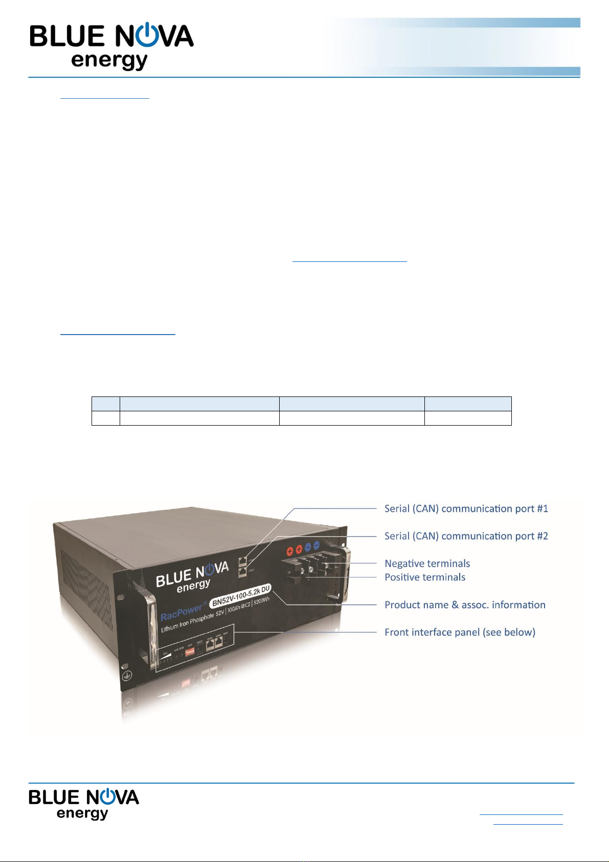
B. STRUCTURAL OVERVIEW
The BlueNova® 52V RacPower range has been designed to be installed in 19” (11U) server racks.
The weight & dimensions of each enclosure in this range is listed below:
Dimensions (L x W x H)
Weight (net)
1
BN52V-100-5.2k DU RacPower
442 x 520 x 178mm
55kg
Note: The dimensions above are the dimensions of the main chassis (excluding the front panel) in each case.
For a more detailed overview of dimensions, please see latest product data sheets.
Diagram: BN52V-50-5.2k RacPower
User Manual
RacPower® BN52V-100-5.2k DU
2 Erica Way Office: +27 21 205 2000
Somerset West Business Park Technical Support: support@bluenova.co.za
Somerset West, 7130 Website: www.bluenova.co.za
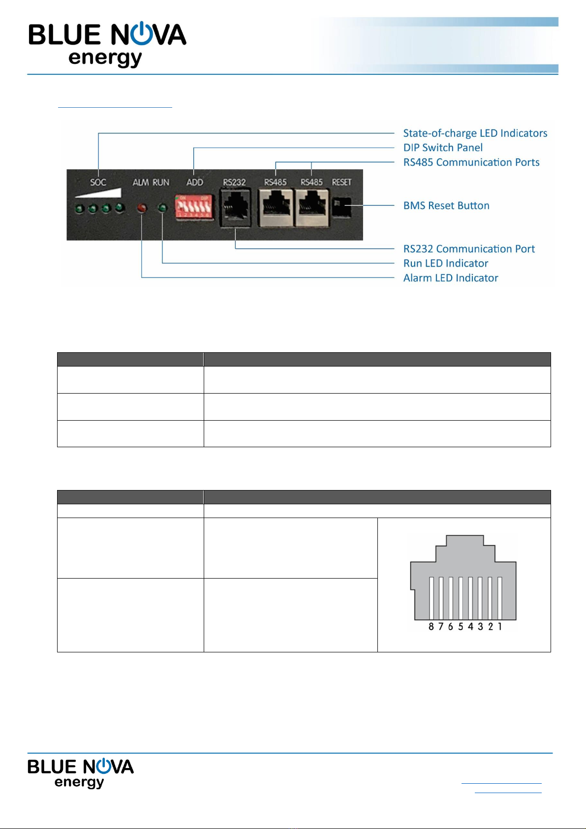
C. FRONT INTERFACE PANEL
Diagram: Front Interface Panel (BN52V-100-5.2k)
SYSTEM START / SHUT DOWN / RESET:
FUNCTION
OPERATION
Start
Press the RESET button for 3s when the battery is in sleep mode to switch it
on. Led on the panel flashes from the Left to Right.
Shut down
Press the RESET button for 3s when the battery is in idle/discharge mode to
switch it OFF. Led on the panel flashes from Right to Left.
Resetting
Press the RESET button for 6s when the battery is in idle/discharge mode to
reset the BMS.
COMMUNICATION PORTS:
COMPONENT
FUNCTION / DESCRIPTION
RS232 (RJ11)
Not active
CAN Ports (RJ45 x 2)
Serial communication via CAN Bus.
PIN configuration as follows:
-7 : CAN-H
-8 : CAN-L
RS485 Ports (RJ45 x 2)
Pin configuration as follows:
-1/8 : A
-2/7 : B
-3/6 : GND
-4/5 : NC

User Manual
RacPower® BN52V-100-5.2k DU
2 Erica Way Office: +27 21 205 2000
Somerset West Business Park Technical Support: support@bluenova.co.za
Somerset West, 7130 Website: www.bluenova.co.za
DIP SWITCH PANEL CONFIGURATION:
Address
DIP Switch Number
Master
/ Slave
(CAN)
Definition
(RS485)
Parallel Configuration
Inverter Protocol
configuration
#1
#2
#3
#4
#5
#6
Inverter
OFF
OFF
Victron250
ON
OFF
Victron500,
SMA,
Studer
OFF
ON
Goodwe
ON
ON
Reserved
Note:
Ensure to have the same
protocol configuration on
all parallel units.
1
ON
OFF
OFF
OFF
Master
Pack1
2
OFF
ON
OFF
OFF
Slave 1
Pack2
3
ON
ON
OFF
OFF
Slave 2
Pack3
4
OFF
OFF
ON
OFF
Slave 3
Pack4
5
ON
OFF
ON
OFF
Slave 4
Pack5
6
OFF
ON
ON
OFF
Slave 5
Pack6
7
ON
ON
ON
OFF
Slave 6
Pack7
8
OFF
OFF
OFF
ON
Slave 7
Pack8
9
ON
OFF
OFF
ON
Slave 8
Pack9
It is essential to set the DIP address number in order when connected with a CAN bus inverter, otherwise the
BMS will report an error.
STATE-OF-CHARGE:
COMPONENT
FUNCTION / DESCRIPTION
State-of-charge indicator
0% –25% SoC
25% –50% SoC
50% –75% SoC
75% –100% SoC
ON
OFF
1
2
3
4
5
6

User Manual
RacPower® BN52V-100-5.2k DU
2 Erica Way Office: +27 21 205 2000
Somerset West Business Park Technical Support: support@bluenova.co.za
Somerset West, 7130 Website: www.bluenova.co.za
LED indicators:
Status
Running
condition
SOC
RUN
ALM
Description
Switch Off
Sleep mode
off
off
off
off
off
off
All off
Stand by
Normal
off
off
off
off
Flash 1
off
Idle
Alarm
off
off
off
off
Flash 3
Flash 3
ALM and RUN Flash 3
Charging
Normal
According to real-time
capacity
on
off
Highest LED Flash 2
OV Alarm
According to real-time
capacity
on
off
Highest LED Flash 2
OC Alarm
According to real-time
capacity
on
Flash 3
Highest LED Flash 2
OV Protect
on
on
on
on
on
off
OC Protect
(charge limit
off)
off
off
off
off
off
on
Stop charging
Charge limit
According to real-time
capacity
on
off
Highest LED Flash 2
Discharging
Normal
According to real-time
capacity
Flash 3
off
According to real-time
capacity indicate
Alarm
According to real-time
capacity
Flash 3
Flash 3
ALM and RUN Flash 3
OC/short
circuit/revere
connection
off
off
off
off
off
on
Stop discharging
UV
off
off
off
off
off
off
Stop discharging
Temp
Normal
According to status
Charge alarm
According to real-time
capacity
on
Flash 3
Highest LED Flash 2
Discharge
alarm
According to real-time
capacity
Flash 3
Flash 3
Protect
off
off
off
Off
off
on
METHOD
ON
OFF
Flash 1
0.25s
3.75s
Flash 2
0.5s
0.5s
Flash 3
0.5s
1.5s

User Manual
RacPower® BN52V-100-5.2k DU
2 Erica Way Office: +27 21 205 2000
Somerset West Business Park Technical Support: support@bluenova.co.za
Somerset West, 7130 Website: www.bluenova.co.za
D. INSTALLATION
1. VOLTAGE-BASED INSTALLATION
If the battery is not connected to hardware that is serial communication compatible, the following values
highlighted in blue must be set on the inverter/charger:
Parameter
Cell V
Value
Comment
V high set
3.44 V
55.0 V
Typical bulk/absorption charge setpoint.
V float
3.38 V
54.0 V
Floating voltage set point.
V reconnect
3.01 V
49.0V
Mains or generator must reconnect to charge batteries.
V low set
2.9 V
46.5V
Inverter must switch off the load.
•Maximum Continuous Charge Current limit = 50 A
•Recommended Charge Current = 30 A
•Discharge Continuous Current limit = 100 A
IMPORTANT: Inverter/charger voltage calibration
Some inverters/chargers have been known to return inaccurate results when measuring voltage.
In such cases, the inverter/charger should be calibrated as follows:
Compare the voltage values displayed by the inverter/charger with that of a calibrated voltmeter.
If the actual voltage differs by more than 100mV from that measured by the inverter/charger, apply this
difference to the highlighted values above (i.e. if actual voltage = 56V while inverter voltage = 56.5V,
the voltage difference = 0.5V should be subtracted from each of the set values above).
Note: Some inverters/chargers have pre-programmed lead-acid related algorithms & functionalities such as auto-
desulfation and equalisation. These functionalities should be disabled, where possible.
2. SERIAL COMMUNICATION
BlueNova® 52V RacPower batteries include serial communication functionality via CAN protocol.
Serial-connecting a 52V NG battery to a compatible inverter, charger or other third-party hardware device
normally negates the necessity of manual voltage-based installation procedures, as described above.
The installation procedure for serial integration varies and is determined by the serial-compatible peripheral
hardware that is being integrated with.
Please note for Victron installations the DVCC must be switched on.

User Manual
RacPower® BN52V-100-5.2k DU
2 Erica Way Office: +27 21 205 2000
Somerset West Business Park Technical Support: support@bluenova.co.za
Somerset West, 7130 Website: www.bluenova.co.za
3. PARALLEL CONNECTION
BlueNova batteries can be connected in parallel to each other to increase overall capacity ONLY IF ALL
the requirements below are met:
a. The nominal voltage of all parallel-connected batteries is the same (52V), and
b. The installed capacity for all batteries is the same, and
c. Each battery is operating within its warranty period.
A total of 9 units can be connected in parallel, for total installed capacity of 46.8kWh @C2, 25°C.


User Manual
RacPower® BN52V-100-5.2k DU
2 Erica Way Office: +27 21 205 2000
Somerset West Business Park Technical Support: support@bluenova.co.za
Somerset West, 7130 Website: www.bluenova.co.za
3.1 PARALLEL CONNECTION: STEP-BY-STEP INSTRUCTIONS
1. Ensure that all units are grounded by connecting each chassis to GROUND from the rear right panel.
Wire diameter should be equal to or exceed 1mm².
2. Connect the POSITIVE terminals of the first (top) unit to the second unit, then from the second unit to
the third etc. as illustrated above. Wire diameter should be equal to or exceed 8mm².
3. Connect the NEGATIVE terminals of the first (top) unit to the second unit, then from the second unit to
the third etc. as illustrated above. Wire diameter should be equal to or exceed 8mm².
4. Connect the CAN port of each unit as illustrated above with a standard 1-to-1 pin RJ45 network cable.
5. Connect the bottom- or topmost unit’s CAN to the third-party serial communication device. Cable
connector pin configuration is determined by the device being connected to. See C. CONTROL PANEL in
this manual for the battery’s RJ45 port pin configuration.
6. Configure the dip switches for the master battery and slave batteries respectively.
7. Ensure that a BlueNova’s CAN-bus terminator (supplied) is inserted in the last battery in the parallel pack.
Also place the inverter manufacturer’s CAN-bus terminator on the inverter’s end.
8. For CAN communication a direct RJ-45 cable is supplied and to be used between Master battery and
inverter. In a case where the inverter’s pin-outs are different from the BlueNova’s battery pin-outs a
custom cable should be made according to the pin-out configuration. As quick reference:
•Victron, Studer –direct cable
•SMA, Goodwe –custom cables
For parallel batteries a direct connection RJ-45 cables should be used between the batteries.
3.2 Start-up sequence for parallel batteries
1. After the system has been fully installed ensure that all the battery units are switched off (All LED’s on
the front panel are off). Ensure that the provided RJ45 cable (black) is connected between the master
battery and the inverter.
2. Each battery should not be tuned on individually! Instead press and hold the reset button on the master
battery only, this will automatically turn on all the batteries in parallel.
3. Ensure that the communication between the BMS and the inverter is functioning correctly by checking
the visible devices on the inverter’s interface.

User Manual
RacPower® BN52V-100-5.2k DU
2 Erica Way Office: +27 21 205 2000
Somerset West Business Park Technical Support: support@bluenova.co.za
Somerset West, 7130 Website: www.bluenova.co.za
E. EXTRA FEATURES
1. Standby Mode
The system will enter Standby Mode immediately whenever the battery is not being charged nor discharged.
In standby mode, the green RUN LED will flash (as with discharging).
2. Sleep Mode
The system will enter Sleep Mode whenever Standby Mode has been active & uninterrupted for 96 hours.
In Sleep Mode, the system will become inactive & all LED’s on the Control panel will switch off.
The system will wake up from sleep mode:
o(automatically) whenever a charge current is detected, or
o(manually) the battery/batteries are switched off and then on again.
F. MAINTENANCE
1. General Guidelines
a. Do not short circuit the battery terminals.
b. Do not use the battery without a BlueNova® approved integrated BMS solution.
c. Do not disassemble, pierce, cut or in any way physically alter any part of the battery.
d. Do not burn, incinerate or otherwise subject the battery to extreme heat.
2. Storage Instructions
a. Ensure that the battery is switched off when stored.
b. Disconnect the communication cable.
c. Always store batteries in a cool and well-ventilated area –ideally 25°C ± 3°C.
d. Store away from moisture and heat.
e. Do not store batteries upside down for overly long periods.
f. Check the open circuit voltage of stored batteries at least once per month. Recharge batteries sufficiently and
frequently enough to prevent the open circuit voltage falling below 40V.
g. The battery needs to be charged every 6 months if out of use.
h. Ensure that the stored battery’s state of charge is always above 50%. 100% SOC is optimal.
i. Don’t place more than 6 units on top of each other.

User Manual
RacPower® BN52V-100-5.2k DU
2 Erica Way Office: +27 21 205 2000
Somerset West Business Park Technical Support: support@bluenova.co.za
Somerset West, 7130 Website: www.bluenova.co.za
G. EMERGENCY & FIRST AID
1. In case of fire
a. Evacuate danger zone. Open ventilation in the room if possible.
b. Extinguish fire with a CO2 fire extinguisher.
c. After the fire has been extinguished, immerse any remaining smoking cells completely in water.
Wear protective gear during this procedure.
2. Skin contact
a. Wash the affected area immediately with soap and water.
b. If irritation persists, seek medical attention.
3. Eye contact
a. Rinse eyes immediately with clean water continuously for at least 15 minutes.
b. Seek medical attention immediately afterwards.
4. Ingestion
a. Refrain from taking any emetic or vomit-inducing medicine.
b. Seek medical attention immediately.
Other manuals for RacPower 52V Series
1
This manual suits for next models
1
Table of contents
Other BlueNova Camera Accessories manuals


