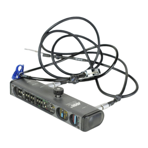
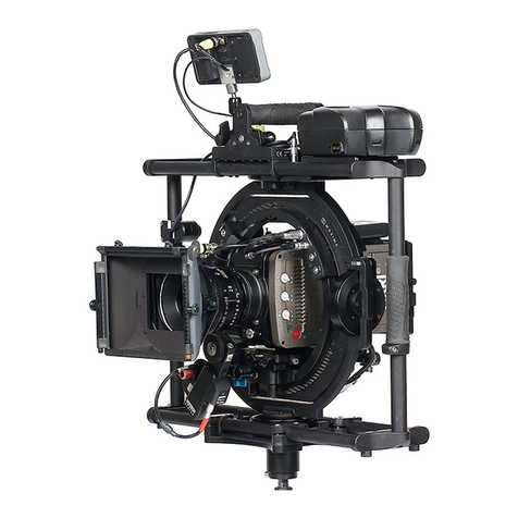
ARRI K2.47050.0 User manual

1
HD- IVS for ARRICAM ST
K2.47050.0
Instruction Manual
May, 18th 2010
K5.40803.0 0035-64-00-00-01 K7601

2
1 Quick Reference................................................................................................ 3
2 Safety Instructions and Legal Disclaimer ......................................................... 5
2.1 Safety Instructions.................................................................................... 5
2.2 Legal Disclaimer ...................................................................................... 7
2.3 Declaration of Conformity........................................................................ 9
3 General Description of the ARRICAM ST HD -IVS ........................................... 10
3.1 Order Numbers...................................................................................... 12
3.2 Installing the HD-IVS Lens..................................................................... 13
3.3 Changing the IVS Lens........................................................................... 16
3.4 Installation of the ARRICAM ST .............................................................. 20
3.5 Outputs ..................................................................................................22
3.6 HD-SDI Output Without Graphic Overlay .............................................. 22
3.7 HD-SDI Output With Graphic Overlay ................................................... 22
3.8 Mini Monitor Output............................................................................... 23
4 Standard Video Controls ................................................................................ 25
4.1 Switch On, Off and Check/Hide Menu.................................................... 25
4.2 Iris.......................................................................................................... 26
4.3 Alignment of the Image Position (X-, Y- and Rotation) ......................... 26
4.4 Focus ...................................................................................................... 27
4.5 White Balance (WB)................................................................................ 28
4.6 Gain Control........................................................................................... 32
4.7 Changing Format marking number....................................................... 34
4.8 Ground Glass Cancellation (GGC) On/Off ............................................. 36
4.9 Ground Glass Cancellation Iris Setting.................................................. 37
4.10 HD Link Speed ....................................................................................... 40
4.11 HD-Link Mode........................................................................................ 41
4.12 Storing a Video Image to Internal Memory........................................... 42
5 Inserter Facilities............................................................................................ 43
5.1 Setting the On-Screen Displays.............................................................. 43
5.2 Main Menu............................................................................................. 45
5.3 Load/Store Menu.................................................................................... 46
5.4 White Balance, Manual Gain Control and Color Bars Menu.................. 50
5.5 Video Adjustment Menu......................................................................... 58
5.6 Format Marking Menu........................................................................... 66
5.7 Compare/Store Menu............................................................................. 70
5.8 System, LDS and Status Info................................................................... 77
5.9 User Text Menu ...................................................................................... 84
5.10 GGC........................................................................................................ 90
5.11 Time Code .............................................................................................. 98
5.12 Meta Data ............................................................................................ 106
5.13 SERVICE ................................................................................................ 108
5.14 Check.................................................................................................... 114
6 Technical Data.............................................................................................. 115
7 Index............................................................................................................. 116
8 ARRI Service Centers..................................................................................... 119

3
1Quick Reference

4
MENU EDIT TEXT

5
2Safety Instructions and Legal Disclaimer
2.1 Safety Instructions
Please always follow these instructions to help ensure against injury to
yourself and damage to the system or other objects.
This safety information is additional to the product-specific operating
instructions in general and must be strictly observed for safety reasons.
Furthermore, you are obliged to incorporate and observe sufficient safety
measures of your own.
Warning signs
This symbol indicates possible risk of injury or damage to the
equipment.
This symbol indicates the risk of electric shock or fire danger that
could result in injury or equipment damage.
General safety instructions
•Read and understand all safety and operating instructions before you
operate or install the system.
•Retain all safety and operating instructions for future reference.
•Heed all warnings on the system and in the safety and operating
instructions before you operate or install the system. Follow all installation
and operating instructions.
•Do not use accessories or attachments not recommended by ARRI, as
they may cause hazards and void the warranty.
•Do not repair any part of the system. Repairs mustbe carried out only by
authorized ARRI repair shops.
•Do not remove any safety measure of the system.
•Do not operate the system in high humidity areas or expose it to water
or moisture.
•Do not place the system on an unstable cart, stand, tripod, bracket, or
table. The system may fall, causing serious personal injury and damage
to the system or other objects.

6
•Operate the system using only the type of power source indicated in the
manual. Unplug the power cord by gripping the power plug, not the
cord.
•Never insert objects of any kind into any part of the system through
openings, as the objects may touch dangerous voltage pointsor short-
circuit connections. This could cause fire or electrical shock.
•Unplug the system from the power outlet before opening any part of the
system or before making any changes on the systems, especially the
attaching or removing of cables.
•Do not use solvents to clean.
•Clean optical surfaces only with a lens brush or a clean lens cloth! In
case of solid dirt moisten a lens cloth with pure alcohol.
•Do not loosen any screws, which are painted over!
•Danger of injury: After switching the drive directionthe focus and iris
motors automatically move.
•The antennas must always be kept screwed on to their bushing to
protect the highly precise antenna bushing (Reverse-SMA).
•In order to ensure optimal radio connection the bushing must be free of
dust and dirt at all times. If necessary, remove the antenna and clean
antenna and bushing using pressured air. Do not use any tools that can
harm antenna or bushing.
Specific safety instructions:
•As the end-stops of the iris ring on the ARRIMACROS change when the
lens is focused, the ARRIMACROS may not be used with the LCS or the
WRC-1 system.
•Danger of injury with the rotating drive gears on the lens barrel, or when
switching the operating direction on the UMC-1, LDB and FEM-2!
•Any violation of the safety instructions or neglect in personal care could
cause serious injuries (including death) and damages on the system or
other objects.
Note:Notes are used to indicate further information or information from
other instruction manuals.
→Photo indicates objects which are shown in the illustration.

7
Product Identification
When ordering parts or accessories, or if any questions should arise,
please advise your type of product and serial number.
2.2 Legal Disclaimer
Before using the products described in this manual, be sure to read and
understand all relevant instructions. The HD-IVS System is only available for
commercial customers. By utilization the customer agrees, that the ARRI
HD-IVS or other components of the system are only deployed for commercial
use. Otherwise the customer has the obligation to contact ARRI preceding the
utilization.
While ARRI endeavors to enhance the quality, reliability and safety of their
products, customers agree and acknowledge that the possibility of defects
thereof cannot be eliminated entirely. To minimize risks of damage to
property or injury (including death) to persons arising from defects in the
products, customers must incorporate sufficient safety measures in their
work with the system and have to heed the stated canonic use.
No part of this document may be copied or reproduced in any form or by any
means without prior written consent of ARRI. ARRI assumes no
responsibility for any errors that may appear in this document. The
information is subject to change without notice.
For current design-in, refer to the latest publications of ARRI data sheets or
data books, etc., for the most up-to-date specifications. Not all products
and/or types are available in every country. Please check with an ARRI sales
representative for availability and additional information.
ARRI and its subsidiaries do not assume any liability for infringement of
patents, copyrights or other intellectual property rights of third parties by
or arising from the use of ARRI products or any other liability arising from
the use of such products. No license, express, implied or otherwise, is
granted under any patents, copyrights or other intellectual property rights
of ARRI or others.
ARRI and its subsidiaries expressly exclude any liability, warranty, demand
or other obligation for any claim, representation, or cause, or action,
express or implied, whether in contract or tort, including negligence, or
incorporated in terms and conditions, whether by statue,law or otherwise. In
no event shall ARRI or its subsidiaries be liable for or you have a remedy
for recovery of any special, direct, indirect, incidental, or consequential
damages, including but not limited to lost profits, lost savings, lost
revenues or economic loss of any kind or for any claim by third party,
downtime, good-will, damage to or replacement of equipment or property,
any costs or recovering of any material or goods associated with the

8
assembly or use of our products, or any other damages or injury of
persons and so on or under any other legal theory.
In the case one or all of the forgoing clauses are not allowed by applicable
law, the fullest extent permissible clauses by applicable law are validated.
ARRI is a registered trademark of Arnold & Richter Cine Technik GmbH &
Co Betriebs KG.

9
2.3 Declaration of Conformity

10
3General Description of the ARRICAM ST HD -IVS
The Integrated HD Video-Assist System (HD-IVS) for the ARRICAM ST is a
breakthrough product, which uses innovative digital technology to create
high definition video assist images for the ARRICAM ST film cameras. Wide
dynamic range, excellent color reproduction and low noise are combined
with ARRI’s unique Ground Glass Cancellation (GGC) technology to create
beautiful, high resolution preview images. The HD-IVS provides a superior
image for the director and cinematographer on the set, allowing them to
judge each take while shooting on 35mm film.
Main Features
•High resolution
Because of a sensor with 1920 x 1080 pixels, the resolution is
dramatically increased resulting in an unprecedented image quality.
•3 Stops more dynamic range than standard IVS
The HD-IVS works internally with 12 bit pixel depth and only for the
output it is re-sampled down to 10 bit. This creates a higher dynamic
resulting in more details in shadow areas.
•Anamorphic de-squeeze
To de-squeeze anamorphic images, the HD-IVS comes with software
options for a de-squeeze factor of 2 and 1.3.
•Screen capture
Individual still images can be stored on a standard USB stick in a
standard bitmap format.
•Ground Glass Cancellation(GGC) for a clean image
The structure of the ground glass in the optical system can be
recognized, stored, and electronically subtracted from the actual image.
Therefore the image does not show the ground glass structure any
more.
•Less noise through optimized exposure control
Because of a motorized iris in the HD video assist the IVS lens is always
controlled so that a maximum amount of light reaches the video assist
sensor. Thus less electronic gain is needed and the noise is reduced.
•Excellent color reproduction
A state-of-the-art bayer mask on the sensor and a high sophisticated
color processing electronic ensure an excellent color reproduction.
•Flicker-free
An integrated digital frame store enables the video camera to be
synchronized to the film camera's mirror shutter and provides (in

11
manual gain control mode) a flicker-free video image from 1 fps to
maximum speed; the video image is always taken at the ideal position
of the mirror shutter.
Flicker free can be switched off to bypass the digital frame store and to
have minimal delay in the video system.
•Full white balance control
Indoor,-outdoor, automatic, manual and one –push white for an
automatic detection of white charts.
•Store and recall settings
All settings can be stored and recalled. Through this, it is possible for
example to trim all the settings for indoor shooting, store them, have
some exterior scenes, go back indoor and call the old settings back.
Up to 6 settings can be stored.
•Integrated frame line inserter
Frame lines can be electronically added to the video image. This
ensures that the frame lines are visible even in difficult conditions. The
area outside the frame lines can be darkened electronically in three
different steps to emphasize the important image area.
•Camera status display
Camera status information, e.g. camera speed and film counter data
are passed on a bus interface from the camera to the video assist and
can be displayed in a camera status line on the monitor.
•System display
Camera system information is available in the video assist. Thus, it is
possible to see camera warnings such as “movement open” or “low
battery” on the monitor.
•Integrated text inserter
Additional text, such as take numbers or production name, can be
added to the video image by entering the text on the HD-IVS.
•On-Screen programming
All functions, which do not affect the image appearance directly, such as
frame lines, can be conveniently programmed with an on-screen
programming menu on the video monitor.
•Dedicated controls
Important image changes, such as gain or white balance, can be done
immediately parallel to the on-screen programming with dedicated
keys.

12
•Image compare function
It is possible to store a particular image and compare it against other
images. This clearly shows the difference between the images, e.g.
during stop effect shots.
•Automatic and manual gain control
The gain is controlled automatically to its best value but can also be set
manually.
•Mini monitor connector:
The HD-IVS has a BNC connector for an HD-IVS Mini Monitor. The mini
monitor needs to get power on a separate power cable.
3.1 Order Numbers
ARRICAM ST HD-IVS order number:
K2.47050.0 HD-IVS for ARRICAM ST
K2.64200.0 IVS Lens for 4:3 Format
K2.64201.0 IVS Lens for 16:9 Format
K0.60096.0 Set HD-IVS ARRICAM ST plus IVS Lens for 4:3 Format
K0.60096.A Set HD-IVS ARRICAM ST plus IVS Lens for 16:9 Format
A 1.5 mm hex key for image adjustment is included in K2.47050.0

13
3.2 Installing the HD-IVS Lens
The HD IVS allows the use of two different IVS prime lenses as a video
assist lens. The 4:3 IVS lens is optimized for taller aspect ratios such as 4:3
or anamorphic formats. The full 4:3 ground glass image will be displayed
on 1440 x 1080 pixels on the HD monitor, leaving black vertical bars to
the left and right of the image (“pillar box”). These black bars optionally
display metadata or the OSD menu.
The 16:9 IVS lens is optimized for aspect ratios of 16:9 or wider. A 16:9
aspect ratio image from the ground glass will be displayed on the full HD
monitor in 1920 x 1080 pixels.
Note: If a 4:3 IVS lens is installed together with a 16:9 ground glass, black
areas will appear not only left and right but also top and bottom of
the monitor screen. The usable image on the monitor will be too
small. Vice versa, if a 16:9 IVS lens is installed together with a 4:3
ground glass, the image will be cropped on top and bottom. Both
situations are not recommendable. Please use an appropriate
combination of ground glass and IVS lens.
This operation should be carried out only by an experienced
technician.
Use appropriate care to avoid electro static discharge.
Do not touch optical surfaces and do not use force.
If you feel uncomfortable in changing the IVS Lens, please don’t
hesitate to consult one of the authorized ARRI Service Centers.
A Phillips PH 1, a 1.5 mm hex key, and a pair of tweezers are needed.
Remove the 5 screws S1 to S5 by
using a Phillips PH1 screwdriver
and open the back of the HD-IVS-
ST.
→Photo
Remove the 3 screws S1 to S3 by
using a Phillips PH1 screwdriver to
open the top of the optics
assembly. →Photo

14
Remove the cover by opening
the screw S1 using a 1.5 mm hex
key. →Photo
The focus ring has to be in the
correct position, to reassemble the
lens:
Turn the focus ring as shown
→Photo until it reaches end stop –
then turn it back a quarter of a
revolution.
Insert the connector through the
hole and insert the lens into the
optics assembly. →Photo
Make sure that the small key on
the lens is aligned with the keyway
in the optics assembly. →Photo

15
Push the lens gently against IVS
and turn the focus screw S1
counter clockwise by using a 1.5
mm hex key until the lens gets
pulled in.
→
Photo
Carefully feed the connector
through the housing and connect it
by using a pair of tweezers.
→Photo
Attach the cover by using a 1.5
mm hex key. →Photo
Insert and close the 3 screws S1 to
S3 by using a Phillips PH1
screwdriver to open the top of the
optics assembly. →Photo
Insert and close the 5 screws S1 to
S5 by using a Phillips PH1
screwdriver and open the back of
the HD-IVS-ST. →Photo

16
3.3 Changing the IVS Lens
The HD IVS allows the use of two different IVS prime lenses as a video
assist lens. The 4:3 IVS lens is optimized for taller aspect ratios such as 4:3
or anamorphic formats. The full 4:3 ground glass image will be displayed
on 1440 x 1080 pixels on the HD monitor, leaving black vertical bars to
the left and right of the image (“pillar box”). These black bars optionally
display metadata or the OSD menu.
The 16:9 IVS lens is optimized for aspect ratios of 16:9 or wider. A 16:9
aspect ratio image from the ground glass will be displayed on the full HD
monitor in 1920 x 1080 pixels.
Note:If a 4:3 IVS lens is installed together with a 16:9 ground glass, black
areas will appear not only left and right but also top and bottom of
the monitor screen. The usable image on the monitor will be too
small. Vice versa, if a 16:9 IVS lens is installed together with a 4:3
ground glass, the image will be cropped on top and bottom. Both
situations are not recommendable. Please use an appropriate
combination of ground glass and IVS lens.
This operation should be carried out only by an experienced
technician.
Use appropriate care to avoid electro static discharge.
Do not touch optical surfaces, do not use force.
A Phillips PH 1, a 1.5 mm hex key, and a pair of tweezers are needed.
Make sure to mount the correct
Lens Type Marker on the HD-IVS,
so that the type of lens is visible
from the outside. For this, unscrew
the screws S1 and S2, attach the
Lens Type Marker and screw the
two screws on again. →Photo

17
Remove the 5 screws S1 to S5 by
using a Phillips PH1 screwdriver
and open the back of the HD-
IVS-ST.
→Photo
Remove the 3 screws S1 to S3 by
using a Phillips PH1 screwdriver
to open the top of the optics
assembly. →Photo
Remove the cover by using a
1.5 mm hex key. →Photo
Disconnect the connector →Photo
by using a pair of tweezers and
pull out the cable carefully through
the top of the optics assembly.
→Photo
Turn the focus screw S1 →Photo
clockwise by using a 1.5 mm hex
key until the lens comes loose and
pull it out carefully. Make sure the
connector slips through the
housing, without being pulled.

18
The focus ring has to be in the
correct position, to reassemble the
lens:
Turn the focus ring as shown
→Photo until the end stop – then
turn it back a quarter of a
revolution.
Insert the connector through the
hole and insert the lens into the
optics assembly. →Photo
Make sure that the small key on
the lens is aligned with the keyway
in the optics assembly. →Photo
Push the lens gently against IVS
and turn the focus screw S1
counter clockwise by using a
1.5 mm hex key until the lens gets
pulled in. →Photo
Carefully feed the connector
through the housing and connect it
by using a pair of tweezers.
→Photo

19
Attach the cover by using a
1.5 mm hex key. →Photo
Screw on the 3 screws S1 to S3 by
using a Phillips PH1 screwdriver to
open the top of the optics
assembly. →Photo
Screw on the 5 screws S1 to S5 by
using a Phillips PH1 screwdriver
and open the back of the HD-IVS-
ST. →Photo
Make sure to mount the correct
Lens Type Marker on the HD-IVS
so that the type of lens is visible
from the outside. For this, unscrew
the two screws S1 and S2, attach
the Lens Type Marker and screw
the two screws on again. →Photo

20
3.4 Installation of the ARRICAM ST
A 3 mm and a 1.5 mm hex key are used.
Take the view finder cover off the camera.
Take the adapter and the IVS lens cap off the HD IVS
Mounting the HD adapter to the ARRICAM ST view finder
To take the adapter off, a 3 mm
hex key is used. Remove the lens
cap. →Photo
To take the view finder cover off,
loosen the captive screw S1 with a
3 mm hex key and remove the
view finder cover. →Photo
To take the adapter off the HD
video assist, loosen the captive
screws S1 and S2 with a 3 mm hex
key. To have access to screw S2
use the hole as marked and
remove the adapter →Photo
Attach the adapter onto the
ARRICAM ST view finder and
tighten screw S1 and S2 →Photo
Table of contents
Other ARRI Camera Accessories manuals
Popular Camera Accessories manuals by other brands

Sony
Sony IPT-DS1 - Party-shot Digital Camera Docking... Supplemental operating instructions

Pylontech
Pylontech PowerCube-H1 product manual

MK Controls
MK Controls Lightning Bug instruction manual

Njoy
Njoy PW12123B user manual

PROAIM
PROAIM CINEMA P-SWCC-10 Assembly manual

Nissin
Nissin AIR 10S COMMANDER instruction manual